When you click on links to various merchants on this site and make a purchase, this can result in this site earning a commission. Affiliate programs and affiliations include, but are not limited to, the eBay Partner Network.
CONTENTS: INTRODUCTION ADDITIONAL INDICATIONS FUEL DELIVERY SYSTEM IGNITION SUPERCHARGER BUILD AND SET UP CONSIDERATIONS SUPERCHARGER INSTALLATION TUNING AND PERFORMANCE DATA
INTRODUCTION:
I'm going to use this thread to describe my current project: C3 centrifugal supercharged 1978 Corvette. I'm a couple of years into the total project, most of which has been idle due to other life commitments. As I get time I will try to describe some of the challenges, post pictures, and answer questions for those who have contemplated or even completed these types of projects. There aren't that many centrifugal SC C3's out there, but perhaps I can add to the forums database of experience / knowledge. Disclaimer: I am a part time garage mechanic at home, and I certainly don't pretend to have all the answers or have some of the artistic skill some of the members on this forum have. I have borrowed the vast information found on this forum to do many things on my corvette, and I figured this would be a good way to document some of my experiences with this project. Most of the material in this thread has been "borrowed" from various sources - I didn't invent this stuff, nor can a take the credit. I've simply compiled my experiences and research for the ease of other users.
As with any project, I started with the idea, of adding power to my C3 like many owners do. Years ago I ditched the original L48 and replaced it with a 1993 HO four bolt main 350 c.i. crate engine from GM performance parts. Over the years I added aluminum heads, hydraulic roller cam, suspension upgrades, etc... ** Update (Feb 2022)** The crate motor has been replaced with a custom built 383 stroker with forged internals. Without getting off the topic, I have a late 70's corvette that has been modified from stock. So, I was pondering what else I could tinker with, when someone mentioned super charging the motor. I thought that would be cool, but I really didn't want to have anything sticking out of the hood, or some of other obvious modification. That's when I learned of the centrifugal superchargers of which there are several manufacturers out there on the market. I then started to do some research into the world of forced induction. Would it even be possible - without getting too crazy - to do to my car?
I then learned that I would have to evaluate my engine, it's parts, fuel delivery, drive-train, ignition, air inlet system, inlet air temperatures, additional gauges, engine cooling, compression ratios, etc... This doesn't even include the challenges of trying to fit this all nice and neat under the hood of C3 corvette. There are many other threads that touch on some and or all of these topics, but I will try and relate them here with respect to this project.
First off, there is no "kit" that I am aware of that is a nice out of the box, bolt on, pre-engineered, clean install. I started out by getting a basic SBC ProCharger kit. This included v-belt pulley's, mounting bracket, the super-charger, and other odds and ends. So, you have to figure out how to make this work for your application. In the following entries I will continue to try and document some of the things I've done, and continue to do.
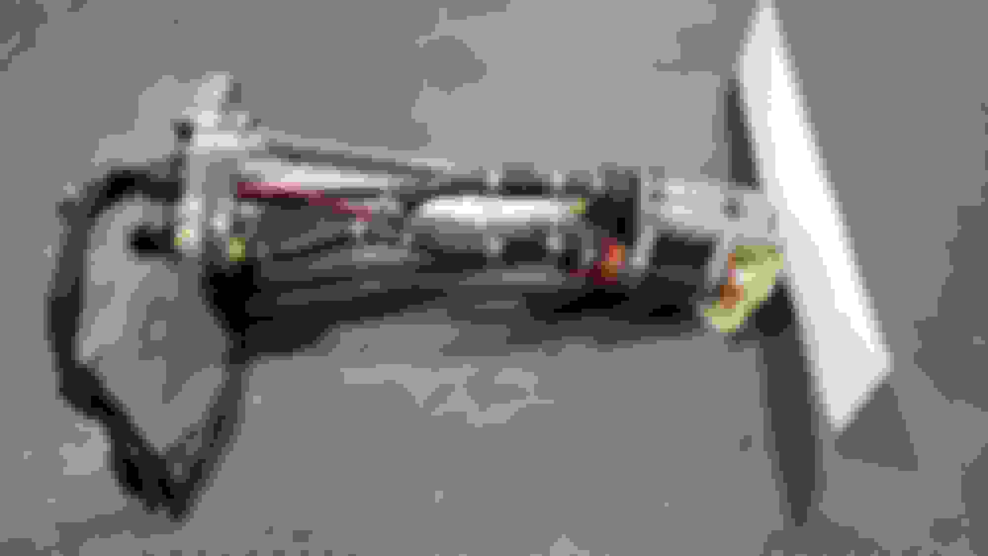
Here is a picture of my Corvette in the with the hood closed - with the supercharger fully installed, and a picture with the hood open and the SC installed under the hood.
I've updated the engine compartment with the new C5 master cylinder. It fits better and doesn't interfere with the intake snorkel.
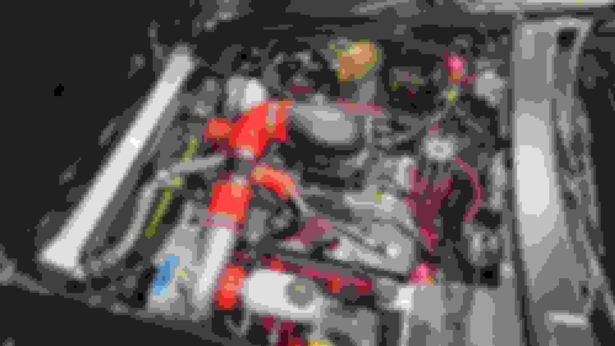
This is the updated engine compartment as built (including the new Hyperspark System):
Here's the new coil and IGN box (which is in the darkness under the fender):
ADDITIONAL INDICATIONS:
The first thing I tackled was the additional gauges I wanted to mount. The 78 doesn't come with fuel pressure or an indication of manifold pressure. I wanted to add both of these. In my case, I've made custom mounting surfaces out of polished aluminum. I made a new backing plate, moved the holes around, and made room for two additional 2 inch gauges by auto meter. I installed an electronic pressure sensor on my fuel manifold, and a manifold pressure sensing line. These things are pretty self explanatory, and are not entirely necessary, but helpful indications when you add forced induction to any vehicle.
This photo has been updated to the as built and includes the LCD for the EFI unit:
FUEL DELIVERY SYSTEM:
A centrifugal SC with a blow through throttle body requires a slightly different approach to delivering fuel to the engine. The big picture - going lean on a forced induction motor, is bad. Not a lot of room for error here. Additionally, the SC is pressurizing not only the air in the manifold like a roots style blower, but the entire carburetor / EFI throttle body and carb hat as well. Fuel being delivered to the carb or throttle body in a standard way either mechanically or electrically needs to be boost referenced in order to overcome the pressure in the throttle body. This is accomplished by installing a pressure regulator that has a ported reference diaphragm. A reference line is then installed from above the throttle plates of the carb / throttle body usually in the carb hat. This allows the regulator to "adjust" as the pressure increases ensuring the proper fuel pressure can be delivered into the throttle body. In my case I used an Aeromotive bypass regulator to do the job.
I also ditched the mechanical fuel pump. You don't have to do this, but you also have to know how much boost you intend to run vs how much discharge pressure your fuel pump will put out at a high flow rate. If the fuel pump can't put out 6 psig + desired boost pressure, then you must upgrade the fuel pump or change some other variable. In my case, I installed **UPDATE (Aug 2022)** a custom fuel sending unit that will fit 78-82 gas tanks. See the pictures below. The new assembly is capable of a two pump operation, or as I installed it with a primary and backup fuel pump. This version puts out EFI pressure, but in my application, the fuel regulator can be adjusted to either carb pressures, or EFI pressures by changing a spring and making fine adjustments. I did this in the case I may want to upgrade to some type of EFI throttle body in the future (which I ended up doing). I have multiple pictures of the fuel project, but will post what the tank looks like externally once the pump was installed. You also have to consider the fuel line sizes AND run a return line for this type of fuel delivery system.
One last thing: electrically I added a three relay system to the electric fuel pump. One relay to "arm" the circuit based on the ignition switch. Then two additional relays to turn the fuel pump on. One was the EFI fuel demand signal, and the seal in relay was the oil pressure switch. This way, if the oil pressure goes away - once the car is running - the fuel pump will turn off regardless of the ignition switch position. A small safeguard in case of an accident.
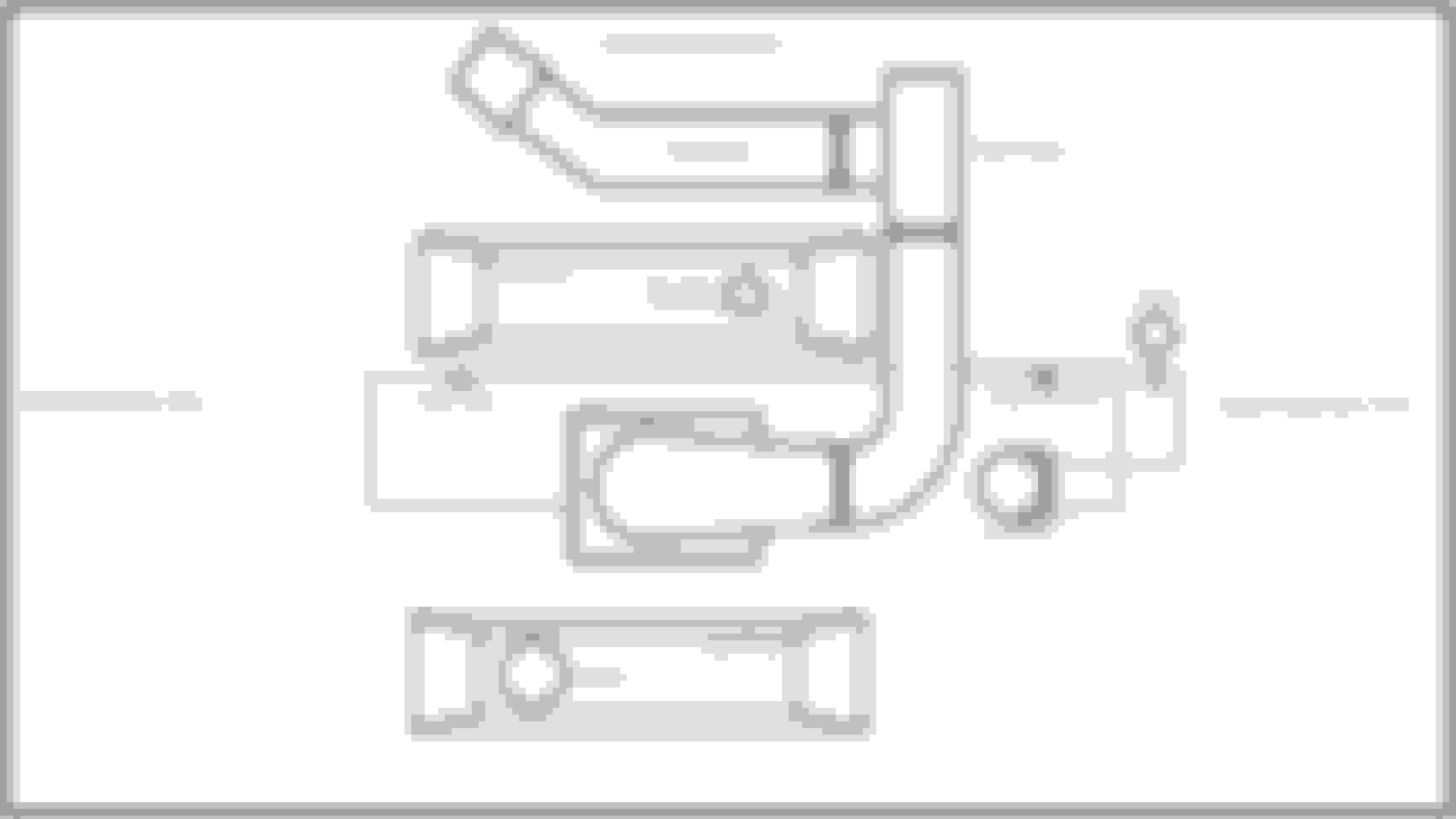
Here is the fuel system schematic with the EFI setup:
IGNITION:
For a blow through SC system (with a bypass valve) your ignition timing under normal driving conditions don't really need to be altered. There are many other great threads in this forum that describe timing, the reasons, and the how's - especially regarding distributors and some of the "old school" timing systems. I opted for a combination of old school and processor controlled timing. If you haven't visited some of the threads on ignition (and read the most current Lars papers) - you should. The information is priceless.
So, under normal driving conditions, the combustion physics are the same as a normally aspirated motor for the most part. Ignition timing doesn't need to be altered. However, under harder driving, in higher RPM ranges, the centrifugal SC starts to build manifold pressure and the timing needs change or you need to protect against detonation. There are lots of factors that affect boost, and different SC's build it differently. The setup for this project - has no inter-cooler. Therefore, heat buildup of the compressed air is a real concern, and so is pre-detonation. Now there are ways to combat this, such as inter-cooling, or various injection systems, lower engine compression, higher octane fuels, and retarding the ignition timing. In fact, some setups require a combination of these things to control detonation. In my setup, I use a combination of timing control, lower static compression, and limiting my SC's boost by finding the optimum pulley size. In this section I'll specifically discuss the timing side of things.
The other thing to consider is the MAP sensor needed for this application. They usually come in 1, 2, or 3 BAR. A BAR is one atmosphere referenced to 0 pounds of pressure - ABSOLUTE. So at 0 pounds you are at an effectively perfect vacuum, and one BAR would be around 14.7 psig at sea level. Normally aspirated engines operate in that 1 BAR range. They have some sort of vacuum at wide open throttle, and a lot more vacuum at lesser throttle positions. Since air isn't getting forced in for NA engines that's all you need. A 2 BAR MAP sensor will get you from 0 psia to about 14.7 psig in the manifold. So if you plan on running anything from 1-14 psi of boost, you'll need a 2 BAR sensor. Beyond that, the 3 BAR sensor will handle manifold pressures close to 30 pounds - and I hope you have a lot more under the hood than a 3 BAR map sensor!
So, the software curves provide a simulated centrifugal curve based upon RPM, and a simulated vacuum advance via the MAP sensor. These things work together depending on the engine conditions. So now you can set things up for either vacuum or boost advance or retarding your timing. It's also relatively easy for me to tweak the exact curves. Just hook up a lap top computer with the MSD software, and tweak points on a graph to get your desired curves. Now what your curves need to be will vary depending on your engine needs and setup. Lars has some solid numbers to get pretty much any V8 in the ballpark of the optimum curves. Beyond that you may need a dyno or other equipment to truly dial something in if your looking for every ounce of ponies squeezed out!
Current Ignition Installation:
About 2 months after driving and tuning the car, my distributor gear self destructed. The root cause of this was probably due to the "iron gear" of the distributor vs "billet steel gear" on the camshaft battle. The iron gear lost the war, and I ended up moving on the the Holley Hyperspark Ignition System. That system included the distributor, coil, and IGN box. The complete system was designed specifically to work with the Holley Sniper EFI system. Most of the above content in terms of timing and ignition concepts are still the same even in the new ignition system. The biggest difference is that the ECU of the Sniper will now control the timing - conceptionally just like my previous setup with the programmable MSD. So, the distributor is made to be "locked in" and you set up the system to be synchronized mechanically with the timing controls of the ECU. You must develop your timing curves on a graph of manifold pressure vs engine speed (RPM). So, this one graph integrates both your centrifugal timing (mechanical) and vacuum timing on one graph. Plus the EFI adds many other features to control timing that my previous MSD setup did not.
Example of a timing graph from the Holley ECU. This graph can also be used for boost applications (such as mine). My actual timing graph is slightly different than this one, but the concept is the same.
This graph takes both the timing of the mechanical distributor and vacuum advance (mechanical) and rolls it into one graph. For example, the timing area where your engine may idle would be in the green area to the left usually around the -4 to -8 psi (notice the units) and 700-1000 rpm depending on your combination. That would put your timing around 25-28 degrees advance. That would be in the ballpark if your base timing was 15 + 10 to 12 degrees of vacuum advance. Notice the timing starts to decrees as manifold pressure goes positive. Where the EFI controlled timing really shines - is where it will control timing in other situations as well. Like engine temperature, or stabilizing RPM during idle etc.
SUPERCHARGER BUILD AND SET UP CONSIDERATIONS:
There is a lot of discussion on engine build details when adding forced induction to the equation. No one will argue that a better built engine - with forged components, high end alloys, etc... will better tolerate the stresses F/I places on an engine. The real question is, are you good enough (the components) to do what it is you want to do? Some times we take calculated risks. Other times, not so calculated. Sometimes we over engineer. In this section I'll try and lay out general guidelines to successfully F/I an engine without turning it into a grenade. Disclaimer: any engine with worn components - driven excessively hard or other variable like that, will probably fail faster if driven hard with F/I. Here are some of the recommendations from ATI ProCharger for basic engine set ups:
The following specifications are general guidelines offered to aide in building an engine for street use. For more detailed specifications regarding your specific application or for "strip only" use, please consult a professional engine builder.
PISTONS
Forged pistons recommended for all applications. Cast and hypereutectic pistons can be used but should be limited to lower horsepower (approx 450-500 hp) applications.
COMPRESSION RATIO
For pump gas (91-93 octane) applications, a compression ratio of 8.5:1 to 9:1 is recommended for boost levels of 8-10 psi. Higher octane fuel will allow you to run higher boost levels, approximately 1 psi for every 2 points of octane. To determine the maximum boost level for your compression ratio (using pump gas), refer to the enclosed compression ratio chart.
HEADS
The same rules for normally aspirated engines apply to supercharged motors. Higher flowing heads will help generate more horsepower than stock heads. Supercharging produces a percentage gain in horsepower; by starting with more base horsepower a modified motor will receive a larger total hp gain (from the same percentage gain). Porting, especially on the exhaust side is recommended. Aluminum heads will allow you to run approximately 1 psi more boost than cast iron heads due to their ability to dissipate heat.
CAM
Lobe separation: 112 to 116 degrees Split pattern: Exhaust duration and lift approximately 10 degrees and .010, respectively, greater than intake. Install cam straight up. Contact a cam manufacturer for lifts and durations that best suit your application.
CRANKSHAFT AND RODS
Cast up to 450 horsepower, forged for higher horsepower or for rpm levels above 6,000 rpm.
EXHAUST
Headers are recommended. The size of headers are dependent on whether you are wanting to create more low end torque or high rpm horsepower.
INTAKE MANIFOLD
Dual planes are recommended to improve low end torque, however may require staggered jetting for good fuel distribution with carbureted applications.
CARBURETOR
Holley double pumper w/ mechanical secondaries. 600 cfm (#4776) for up to 500 hp 650 cfm (#4777) for up to 650 hp 700 cfm (#4778) for up to 750 hp 750 cfm (#4779) for up to 900 hp All carburetor�s will require removal of the choke assembly and choke horn, replacement of the floats with the solid nitrophyl floats and jetted to suit your motor.
FUEL PUMP (CARBURETED APPLICATIONS)
Your fuel pump must be capable of supplying the proper amount of fuel flow at the maximum operating pressure. To determine maximum operating fuel pressure requirement, add your maximum boost pressure to your initial idle fuel pressure.
Most of the literature I have read, stock engines generally don't want to run more than 6-8 psi of boost. That is a general rule, and I am sure there are exceptions. There are also differences in the centrifugal SC's vs the roots style SC's. They are not completely apples to apples when discussing some of the applications and or limitations. When in doubt - fail conservative. Unless you want to rebuild an engine. I'm sort of hoping mine dies, then the super charged 383 stroker will be next! **Update (Feb 2022)** New custom built 383 with forged internals.
Wastegates vs Bypass Valves:
Centrifugal SC compressors are very similar to the turbo counterparts except on how the compressor is spun. One is belt driven, the other is exhaust driven. These characteristics are similar yet different. A supercharger doesn't "spool up". It's speed is directly related to engine speed via the belt and pulley ratios. Therefore, the centrifugal SC doesn't need a "wastegate" because its boost will be limited by pulley sizes and can be altered as necessary. From ProCharger literature:
BYPASS VALVES ARE NOT WASTE GATE RELIEF VALVES
Contrary to most perceptions a bypass valve is designed to relieve boost/pressure when the throttle blade is closed. Conditions such as idle, during shifts, and backing off throttle during tire slip conditions are very important to have a bypass valve. A bypass valve utilizes a vacuum line port behind the throttle blade and vents when detecting an immediate change in pressure. Bypass valves are different from a wastegate relief valve, which operates as a pressure relief valve and opens or vents excess pressure when a certain pressure is achieved.
WOULD YOU EVER WANT TO INSTALL A WASTE GATE RELIEF VALVE WITH A PROCHARGER SUPERCHARGER?
The correct answer is no. Our superchargers are designed to provide maximum boost and efficiency at the maximum engine rpm and by adding a wastegate relief valve to vent that boost is defeating the whole purpose of having an efficient ProCharger supercharger. Proper supercharger pulley size and knowing how much boost your engine can handle at its rated max rpm are the keys to success with a proper ProCharger setup.
Piston Ring Gap Considerations: from : Wiseco ring gap For a street engine, multiplying your bore size by 0.004in will give you the top ring gap you are looking for.
004 x 4.00in bore = 0.016 inch ring gap
For high performance engines, the multiplier changes to add more clearance, but the math stays the same:
Modified or Nitrous Oxide - 0.005in x 4.00in bore = 0.020 inch ring gap
High Performance Racing - .0055in x 4.00in bore = 0.022 inch ring gap
Racing with Nitrous/Turbo - 0.006in x 4.00in bore = 0.024 inch ring gap
Racing Blower/Supercharger - 0.007 x 4.00in bore = 0.028 inch ring gap
For the second ring, the process is the same, but with a slightly different gap, based on application:
Street - 0.005in x bore size
Modified or Nitrous Oxide - 0.0055in x bore size
High Performance Racing - 0.0053in x bore size
Racing with Nitrous/Turbo - 0.0057in x bore size
Racing Blower/Supercharger - 0.0063in x bore size
The reason for these variable specifications is that different types of engines put radically different heat and pressure loads on the ring package. DiBlasi explains, saying, �Let�s look at an LS3 engines that many of our customers have, including myself. If you are building a fun street naturally aspirated LS3 you can expect about 525 horsepower out from it. The heat the rings will see will be very similar to what they are in factory form. Let�s take another person with an LS3 that drops in a new Eaton 2650 positive displacement blower. They can make about 1,100 horsepower out of the same bore, stroke, and general engine combination as the N/A guy. With over double the power output it will significantly increase the cylinder pressure and heat that rings will see. The ring end gaps will need to be substantially larger than the engine with 525 horsepower.�
SETTING UP A SUPERCHARGER
Setting up the fuel and ignition systems to get a blown engine to run properly may take some time, but the results are worth it. The engine must be built with the supercharger in mind, the compression ratio, as well camshaft should be matched to the application and designed use. Always select the camshaft to match the rpm band the engine will normally be operated in, a race cam may make power at high rpm but it will not run well at lower engine speeds. There are a few �set-ups� not used on a normally aspirated engine that can make all the difference in how the engine runs. The camshaft lobe separation that seems to work best for a supercharged engine is 112 to 114� along with a split duration camshaft where the intake lift and duration may be mild yet a more aggressive exhaust cam profile. This type of camshaft can be used on a supercharger since you are blowing the air in to the cylinder; this type of camshaft creates more horsepower without hurting low rpm torque. Using exhaust gas analyzers and advance timing lights allows us to tailor the fuel and ignition advance curves to unleash all the horsepower the supercharger is blowing into the engine.
Blow through carburetor supercharged set-ups
The first concern for an engine using a blow-through supercharger where the carburetor is under boost pressure is fuel pressure. A special fuel pressure regulator that is boost pressure referenced along with a high pressure/volume fuel pump to keep the fuel pressure correct for this type of supercharger system must be used. The boost referenced pressure regulator senses the boost pressure and then regulates the fuel pressure to keep the fuel pressure at a set amount above the boost pressure. The pressure that we use most is 5 � to 6 lbs. over the boost pressure, so when you have 6 lbs. of boost the fuel pressure would be 11 � to 12 lbs. The floats used in the carburetor on a blow thru supercharger must be made of nitrophyl or of some other solid material, brass or hollow plastic floats will collapse from the pressure the supercharger puts into the fuel bowls. The 2 main ways of pressurizing or blowing through the carburetor are #1 where the carburetor is in a pressurized box and #2, is the use of a hat in place of the air cleaner on top of the carburetor. If the carburetor is not inside of a �box� but using a hat to pressurize the carburetor bowls & venturi, the throttle shafts will have to have seals installed to keep the fuel from blowing out thru the clearance in the throttle shaft. We always recommend a marine type of flame arrestor be used inside the air box or hat to defuse the air-charge, if this is not used the air charge blowing from just one side of the carburetor will cause the air/fuel mixture to be incorrect as the boost changes.
The idle and off-idle systems are the hardest part of the fuel system to get the fuel curve correct with a blow-through supercharger system, extreme care must be taken to properly size the idle fuel and air restrictions in order to obtain the correct idle and part throttle fuel mixtures. The reason this care must be taken is because this type of supercharger is pressurizing the idle air bleeds thus blowing the fuel into the engine thru the idle system. The rest of the carburetors fuel circuits operate in a normal fashion. The fuel mixture at idle speeds and cruise speeds seen most are idle CO of 1 to 3%. The cruise mixture on a low boost, mild cam engine would be 1 to 1.5% CO while the high boost pressure hot cam cruise mixture is 3% CO. A power mixture of 6.6% CO (12 to 1 air/fuel mixture) is used on most engines, yet you can go richer if needed to help control detonation.
Selecting the correct carburetor
Selecting the correct carburetor for a supercharged engine is very important; the fuel curves for a low boost engine versus a high boost engine make proper carb selection very important. The Demon carburetor line from Barry Grant Inc. offers carburetors designed for use on supercharged applications; these carbs are in their Race Demon series of carburetors. These carburetors come with removable sleeves; this feature allows you to change the carburetor airflow (cfm), so if you change boost pressure, engine size, or cam, you can resize the carb for the new engine without buying a new carb. The Race Demon series carb also has changeable air bleeds and idle feed restrictions; this feature makes it easy for your tuner to dial in the fuel mixture curve for the engine�s needs.
The blower Mighty and Race Demon carburetors have power valves with vacuum tubes that allow the power valves to be boost referenced, just connect this port to boost pressure and the power valve can see engine load or vacuum instead of the vacuum created by the supercharger. A boost referenced power valve helps make it possible to get the fuel mixture curve correct for all engine loads and should be used on any high boost street driven engine. One of the more common problems I have seen is with the engine at idle speed; the engine will go into a supercharger roll (the engine speeds up the slows down then speeds up�.). This supercharger roll is caused by the superchargers vacuum signal to the power valve not being the actual engine vacuum, but the vacuum created by the supercharger. The power valve reads the higher vacuum created by the supercharger, this vacuum closes the power valve, causing the fuel mixture to go lean, the engine then slows down due to the lean air/fuel mixture so the vacuum signal from the supercharger causes the power valve to open as the superchargers vacuum drops, so again the engine again speeds up due to the richer air/fuel mixture, rolling from rich to lean causing the engine to speed up then slow down.
The fuel pressure we use most is 5 � to 6 lbs. and we always suggest a high volume fuel pump that can supply enough fuel to keep the pressure constant at all engine loads. We have seen Holley style carbs where we had a fuel leak from the plugs on the metering block; this was caused by a carb air scoop creating a high pressure in the fuel bowls pushing fuel past poorly fitting metering block plugs. The cure for this was to epoxy the plugs in the metering block and putting a few vent holes in the carb scoop to help lower the air pressure (this problem has not been seen by us on Demon carbs or on AFB style carbs).
AFB style carbs on a low boost pressure - mild blown engine can work well, but since they do not offer a boost referenced power system, care must be taken to avoid overly lean fuel mixtures, especially at off-idle to part throttle. A street driven dual 500-cfm afb set-up can be a very good running set-up on a mild blown engine that gives a great appearance and also can run well under normal street driving conditions. The 500 & 600-cfm carbs can be modified to avoid an off-idle lean condition, so they can work well on a low boost pressure single or dual carburetor set-up, but we avoid the 750 and 800 cfm AFB�s on street driven blown engines because of a lean at part throttle problem that is inherent with this type of carburetor.
Jetting a supercharged engine
The method we use to determine and then obtain the correct air/fuel mixture (jetting) is on an engine is the use of a tool from OTC/SPX tool company, the PerformanceGas and MicroGas portable exhaust gas analyzers, both units have provided us with accurate data that allows us to obtain great results. The CO reading that an exhaust gas analyzer provides is an accurate indicator of the air/fuel mixture (jetting). Jetting or obtaining the correct fuel mixture on a supercharged engine is different on a low boost engine when compared to a high boost application. On a low boost application the air/fuel mixture is almost the same as a normal hot rod fuel curve, but when a set-up is used with a lot of boost, the fuel mixtures used can be much richer. On a low boost engine the power mixture we use is a CO reading of 6.6% or a 12 to 1 air/fuel ratio, but when using a lot of boost a power mixture 0f 11.5 to 1 air/fuel or CO reading of 8.0% is not uncommon. This richer mixture can help in controlling detonation created by the high boost pressure, but if you go too rich you will lose power. The cruise mixture on a mild cam low boost pressure engine would be 1% TO 2% CO (14.1-13.8 TO 1 air/fuel ratio) but on a hot cam high boost engine the target mixture would be 3% CO (13.4 to 1 air/fuel ratio).
A blown engine will require the accelerator pump to be tailored to its needs; some engines will need a quicker accelerator pump squirt, others will need more accelerator pump volume. Always avoid drowning the engine with too much accelerator pump. A street driven supercharged engine with 2 Holley style carbs will very seldom need 50cc pumps on the primary side of the carbs.
Intercoolers / cooling the charge
The act of compressing the air charge into the engine creates heat; it is not uncommon to see air charge temperatures in the 200 to 250 degree plus range. This heating of the air charge hurts engine performance by reducing the air density. By cooling the air charge you can gain back about 1% in horsepower for every 11 degrees you can drop the air temp, by using an intercooler, it is easy to get a 10% increase in power or more.
Fuel injection with an add on blow through supercharger
If factory fuel injection is used and you do not use an intercooler the vehicles computer may �see� air charge temperatures that are not in the computers program. If a computer sees data that is not in it�s program, it may cause the engine to run poor or not at all. In most cases when adding on a supercharger to a fuel injected car, higher flow fuel injectors be needed and the computer may need reprogramming for the engine to perform properly. A mass air flow equipped fuel injection system will be the easiest type of fuel injection to add a supercharger to since this type of injection can �see� the extra air being feed to the engine and therefore can calculate the correct amount of fuel needed. Speed density fuel injection systems will require reprogramming for a supercharger.
Ignition system set-ups with a supercharger
The ignition system used on a supercharged engine must be up to the job; the higher the boost pressure, the more ignition output is going to be required to fire the spark across the spark plug gap. This higher ignition output will also require the wires and the rest of the ignition system to be up to the job of delivering the extra ignition output to the spark plugs. Always consult the ignition supplier of the product you are using for the recommended spark plug gap when using a supercharger; use these specs as a guideline for where to start. Some experimentation may be needed to find the spark plug gap that works best for your engines demands and the air-fuel mixture inside the cylinder. The use of a engine ignition analyzer to check the condition and output of the ignition system can confirm if the ignition system has enough spark output to handle the extra ignition output needed to fire the sparkplugs because of the higher combustion chamber pressures created by the boost from the supercharger. The ignition system analyzer we use to check a ignition system is the Vision Premier or the Genisys Scope Module from OTC/SPX, either unit allows us to easily check the output and condition of the ignition system.
An MSD ignition system such as a #6btm (boost timing master) may use a spark plug gap of up to .042� with 6 psi of boost. The higher the boost (combustion chamber pressure) the smaller the plug gap, we have seen spark plug gaps of as small as .018 - .022� on a high boost engine with a Msd ignition system. (Note a 9 to 1 non-supercharged engine may use a plug gap of up to .055�.)
The ignition advance curve, in general, is quicker yet shorter than an engine without a supercharger, this helps give better throttle response until the boost pressure kicks in. The advance curve most seen is an initial timing of 18 degrees with a total of 32 degrees; this is just a starting point and must be tailored to each engine. MSD can supply a boost retard ignition system, which allows an advance curve that can supply enough advance to give good throttle response yet, as the boost comes in, it can retard the timing to avoid detonation. The boost retard system can retard the timing from 1 to 3 degrees per pound of boost and total retard can be as much as 20 degrees. A vacuum advance should only be used in a low boost application and should be limited to 10 degrees of advance with engine vacuum above 10 to 12 inches of vacuum. The best way to check and set the advance curve is on a distributor test stand, then confirm the results with an advance timing light such as the type we use from the Black Light series of timing lights supplied by OTC/SPX Tool Company.
So there�s the long and short of it. If you are going to run a blown engine, the right carburetors and ignition system that are tuned for your engine with the proper tools will make your hot-rod experience enjoyable and trouble free.
Compression Ratio
The higher the compression ratio, the more natural torque an engine produces. Adding forced induction increases the effective compression of an engine, because although you have the same compression ratio, air and fuel are entering the cylinder already at a higher pressure. This increase in pressure translates into a bigger bang at ignition, and a larger pressure from the expanding exhaust gases - resulting in more power.
Dropping the compression ratio allows a higher amount of induction pressure to be used, meaning a greater volume of fuel and air can be squeezed into the cylinder. This results in a big increase in torque and power - as long as that volume is being delivered.
When the turbocharger or supercharger is not delivering the full volume - when it's 'off boost' then the engine is relying on a lower amount (and pressure) of air coming in, which results in less power. This breathless lack of power is often mistakenly referred to as lag.
A low compression engine with big induction pressure will perform very poorly 'off boost' (i.e. when the turbo/supercharger is not delivering), and will very rapidly build power as it comes 'on boost'. In extreme cases this can literally be like flicking a switch from no power to instant full power - and a car that will be quite a handful to drive hard. Depending on the induction device, this 'boost threshold' can be quite high in the engine rev range.
A higher compression engine with low induction pressure will perform much better 'off boost' because it still has its own natural compression to generate power; it will generally not have a big jump in power, and as the induction device is generally smaller, its boost threshold will be much lower.
A low compression, big boost engine will make an insane amount of top end power, but be very wheezy and powerless down low, whereas the same sized engine with higher compression and lower boost will be very torquey low down, but won't make as much top end power.
There are certainly reasons to try to raise compression ratio, namely when off-boost performance matters, like on a street car, or when using a very small displacement motor. But when talking purely about on-boost power potential, compression just doesn't make any sense.
People have tested the power effects of raising compression for decades, and the most optimistic results are about 3% more power with an additional point of compression (going from 9:1 to 10:1, for example). All combinations will be limited by detonation at some boost and timing threshold, regardless of the fuel used. The decrease in compression allows you to run more boost, which introduces more oxygen into the cylinder. Raising the boost from 14psi to 15psi (just a 1psi increase) adds an additional 3.4% of oxygen. So right there, you are already past the break-even mark of losing a point of compression. And obviously, lowering the compression a full point allows you to run much more than 1 additional psi of boost. In other words, you always pick up more power by adding boost and lowering compression, because power potential is based primarily on your ability to burn fuel, and that is directly proportional to the amount of oxygen that you have in the cylinder. Raising compression doesn't change the amount of oxygen/fuel in the cylinder; it just squeezes it a bit more.
Final compression ratios above 12.4 to 1 are not recommended for use with "premium pump gasoline." The higher the final compression ratio the higher the octane rating of the gasoline must be in order to help prevent detonation and serious engine damage.
SUPERCHARGER INSTALLATION:
This topic sort of needs to be broken down into some sub-topics. Since you can't buy a kit that takes care of all the installation details for you, you have to sort of figure it out. I bought a P1SC ProCharger with the SBC carburetor / v-belt pulley kit. Basically it came with the ProCharger, mounting brackets and tensioner, crank pulley for v-belt and SC pulley, new alternator pulley, water pump pulley, low profile carb hat, bypass valve, outlet tube with bypass line outlet, inlet air filter, and a bunch of odds and ends. Now, what to do with all that. Here are some of the mounting / installation problems that you have to overcome:
If you bolt on the mounting hardware for the bracket as is, your hood won't close (unless you have a special type of hood). The SC sits too high and close to your fender where the hood is at its lowest.
The SBC mounting kit is designed to be mounted on the drivers side of the engine. That is where the C3 alternator is.
The new crank pulley will force you to relocate the power steering pump / pulley.
Power brakes and headlights require vacuum to operate - while F/I pressurizes the manifold.
The new water pump pulley works great - as long as you have a long snout water pump - which stock C3's do not.
The hood latching arm will now interfere with the SC unit - once you get it to fit right.
Whatever the carburetor you had before, will not work as is with a blow through SC. EFI with forced induction options, not all base systems will work with forced induction.
The air intake or suction side of the SC will interfere with pretty much everything on the drivers side. That includes the master cylinder, engine, steering shaft, etc...
PCV will not work when you need it most as it is for a stock engine.
The SC discharge will require a bypass valve system - to prevent compressor surge.
Intercooling is almost logistically impossible due to the way the C3 hood opens - and how the radiator effectively cuts off the nose access from the engine bay.
I will attempt to address the individual items listed above in the following sub-sections:
1. If you bolt on the mounting hardware for the bracket as is, your hood won't close (unless you have a special type of hood). The SC sits too high and close to your fender where the hood is at its lowest.
Everyone who own's a C3 knows the limitations of space under the hood. The SC kit and mounting bracket available for most SBC applications force you to mount the SC on the drivers side of the engine. For this application the "out of the box" mounting bracket was too high and too far out to work. There is also a mounting block that is sold by ATI (makers of the procharger), that can help relocate the mounting bracket. It is simply an aluminum block with additional mounting holes for re-positioning the SC mounting bracket. I used this, but it still didn't give me the clearance I needed. So I ended up drilling new holes in the actual mounting bracket and installing new bolts through the new holes into the cylinder head. I used the hole at the end of the bracket (closest to the water pump) to "pivot" the bracket. I then marked the desired hole location with respect to the cylinder head holes. WARNING: If you go too low and drop the SC right above the shock tower, you may run into belt interference on the shock tower. You have to account for the drive belt path to the lower side of the new crank pulley. This will determine how low you can go with the SC. In this case, since I effectively shortened the distance both vertically and horizontally - I had to resize my 8 rib belt. The one sent with the kit was too long - even with the tension-er taking up the slack. So you must balance the height between hood clearance, and belt clearance on the lower side of the two pulleys.
That covers the vertical positioning, but be aware of the side to side positioning. Too close and the SC will hit the cylinder head valve covers. Too far away and you'll run into the fender wall. There is a sweet spot, and you don't have much more room in any direction. Anticipate having to modify the mounting bracket with new holes, and possibly removing some material (not to compromise strenght - just fitment).
Also, for a drivers side SC mount, make sure the clocking of the SC is correct. For the ATI ProCharger, the clocking should be the 2:00 o'clock position. This ensures that the oil slinger is at the bottom of the unit for proper lubrication. They have a 10:00, 12:00, and 2:00 option, and the way that you know is based upon the nameplate. The nameplate should be "on top" when the SC is mounted - indicating that the slinger is on the bottom as designed. If the nameplate is on the side or skewed off to the right or left when you mount the unit, it may be clocked wrong and suffer damage do to improper lubrication. I'm not sure how other manufacturer's reference their clocking, but it's probably similar.
Another thing to consider when installing the SC, is the ability to perform oil changes on the unit. It is self contained, meaning it doesn't rely upon the engines oil for lubrication, it has it's own. The drain plug will not be easily accessible in a C3 engine bay. I purchased the drain plug "extension kit". It's basically a stainless braided line that connects to the drainage port and allows access underneath the vehicle to remotely drain the SC unit. The only other alternative is to remove the unit to access the drain plug.
2. The SBC mounting kit is designed to be mounted on the drivers side of the engine. That is where the C3 alternator is.
This isn't that hard to overcome. There are many SBC with alternator's on the passenger side. Now if you have A/C and want to maintain that, there are additional mounting brackets to accommodate that. Easier yet, you could convert everything to a serpentine belt and solve some of these problems with the project. The only real difficulty is coming to grips with re-routing electrical wires, which is just generally tedious work. The kit provides an alternator pulley, and that will align the alternator on a passenger side front mount to align with the new groove on the SC crank pulley.
3. The new crank pulley will force you to relocate the power steering pump / pulley.
The new SC crank pulley v-groove for the power steering pump is closer to the block than the OEM positioning. I believe there are some relocation kits available, I opted to create an aluminum adjustable mounting block - similar to ones you can buy, but they didn't quite work. This allowed me to mount the power steering pump, re-position it, and lock it down.
This is an example of the new power steering bracket to slide the pump just a bit further back to line up the pulleys. Be aware of the frame down below, it gets pretty tight down there. Other options - you could go with a different style of P/S pump and position as necessary. I opted to keep the OEM pump / reservoir but did this to re-locate it. Also, just as a side bar of information, once you get the SC installed, I don't think I can get to my P/S pump without removing the SC. No changing fluid or checking the fluid there easily...
Here's a closer frontal picture of the P/S pulley (to the right) with respect to the crank pulley (to the left):
4. Power brakes and headlights require vacuum to operate - while F/I pressurizes the manifold.
Some C3 owners don't have an issue with this. Some do. The bottom line is that systems that utilize vacuum can be affected by forced induction. Generally speaking your brakes won't be that affected - unless you keep your foot on the gas while hitting the brake. If you come off the gas - vacuum should build in the manifold as the boost pressure decays away. Headlights - I'm not sure. Depends on how tight your system is or was. My solution was to replace most or all the vacuum driven systems with other alternatives. I did most of this before I even decided to force induce my C3. I've replaced the brake booster with a hydraboost. Basically it's a hydraulic unit that operates off from the power steering hydraulic pressure for brake assist. You can see a picture of it above in the engine bay picture. I also converted my headlight actuators into electric motor controlled units. There are other threads that deal with that conversion. That has been wonderful. Some of your heating / cooling controls may have a vacuum feed for vacuum switches and the like. I don't really know if or how much these are affected. Probably not much unless you are flat out racing, in which case I'm sure you don't have the heat on. I would say the headlight operability might be the only real issue, and that may or may not require a "fix". Personal preference, but not entirely necessary.
5. The new water pump pulley works great - as long as you have a long snout water pump - which stock C3's do not.
Converting to the long style water pump isn't difficult. For a SBC, there's literally hundreds of options. The main hurtle is if you still have a stock clutch driven cooling fan for the radiator. My fix was the fact that I had already converted to an aluminum radiator with dual thermostatically controlled cooling fans. This freed up the space between the front of the engine and the radiator since the shroud was also removed. You can run any type of water pump you need at that point.
Here's the water pump / alternator / crank pulley arrangement:
6. The hood latching arm will now interfere with the SC unit - once you get it to fit right.
See installation comment #1. The SC has a tight fit, and this tight fit will generally not allow room for the hinge style hood locking arm to fold down properly. The solution I went with was to purchase a hydraulic arm or rod for the C3 (various kits are out there), and mirror the mounting brackets on the drivers side to apply them on the passenger side. This turned out to be one of the easiest modifications - and worked like a champ. See below:
7. Whatever the carburetor you had before, will not work as is with a blow through SC.
You have several options here. Converting to EFI, installing a carburetor pressure housing (Vortec does this I believe), modifying your existing carburetor (ATI has instructions on this), or purchasing a "blow-through" carburetor - which is designed for this application.I decided to forgo the carburetor route, and complete the conversion to the EFI. I ended up using the Holley Sniper EFI unit part # 550-519. I had already converted the fuel system to an EFI ready system with the Aeromotive in the tank kit. I just had to change the routing to the EFI unit and change the spring in the Aeromotive fuel regulator. This will make the tuning much easier since the computer will do it for me. The Holley will allow for "richening" up the mixture under boost as well as a bunch of other features.
New EFI unit:
The LCD mount for the EFI:
O2 sensor bung in 4" diameter side pipe:
8. The air intake or suction side of the SC will interfere with pretty much everything on the drivers side. That includes the master cylinder, engine, steering shaft, etc... 9. PCV will not work when you need it most as it is for a stock engine. 10. The SC discharge will require a bypass valve system - to prevent compressor surge.
(Items #8, #9 and #10 will be addressed in this section). In my opinion, this part of the project kept me up at night. Well, not really, but I was afraid to go through all of the mechanical fitment problems to simply find out - there was no room to install a decent air intake tube / filter. I also didn't want some sort of crazy flexible snorkel pipe with my air intake laying on the top of the engine or something like that. I also had a the additional problem of an aftermarket hydraboost, with a Wilwood master cylinder. The overall length was longer, and came even closer to the suction eye of the SC impeller. So once I finished the installation of the SC, and it was mounted, I addressed the next fitment problem. Here is what I came up with:
As you can see, I reduced the intake diameter from 3.75" to 3" with silicon reducer. The rest of the tubing is 3" down to the intake filter. I also added the new PCV barb which will become the new location for the suction force of the PCV system. The good news, the system fits (barely) and the air filter resides right behind the drivers side "gill" for a little bit cooler air access. That took a few trial and errors to get that right, but that's how it ended up. The bad news is, I have to unbolt my master cylinder to change / clean the air filter! The whole snorkel is unbolted from the SC and it slides right out of that hole - once you remove the master cylinder. Fortunately, the MC is on by only two bolts - and I have it attached via stainless steel brake lines so I can easily move it out of the way without getting into the brake system. This is my carburetor version prior to the EFI, but it is to show the intake snorkel and how it is configured. See below:
The other problem that I didn't initially address regarding #8 from above, was the MC + the Hydraboost would rub on the intake snorkel. Since the MC is fixed to the car and the SC would vibrate with the engine, this would eventually result in a hole rubbed into the intake snorkel. So, I had to come up with a new MC or some other solution. It was brought to my attention (via this forum), that for my application, the C5 MC would probably work. It was overall shorter, lightweight, and would bolt up to the Hydraboost. You will have to work out the difference in fittings - if you go this route to solve the length problem. The front port (rear brakes) of the MC has a 12mm x 1 bubble flare fitting. The rear port (front brakes) of the MC has a 12mm x 1.5 bubble flare fitting. This will require a conversion fitting or new brake lines to your transfer block below if you have stock C3 lines. In my case, I had converted my lines to hydraulic -4AN lines to the transfer block. I had to go from the metric bubble flare fittings listed above to the -4AN fittings from my previous modification. I did this with two fittings. I adapted the metric bubble flare fittings to 7/16-24 inverted flare fittings, then to the -4AN fittings. Once assembled, the MC no longer sets up against the snorkel intake allowing there to be a clearance between the MC and SC.
Back to the PCV system. Update (Nov 2020): I've learned through both research and my own tuning that the PCV system for a supercharged engine can be both complex and simple. For my own purposes, I want a good functioning PCV system at both idle engine speeds (low loads) and at boost (positive manifold pressures). My initial design utilized the the supercharger for vacuum. In the direction of air flow: Valve cover breather ==> crankcase ==> PCV valve opposite valve cover ==> catch can ==> suction side of the SC impeller. However, I learned through both experience and reading, that the SC didn't generate enough vacuum at low loads to effectively evacuate the crankcase. So I needed either the engine or a vacuum pump at low loads and the super charger at high loads / boost. The answer was to get several sensitive yet robust check valves for the PCV system. Tie the engine manifold line (with check valve for boost conditions) to the SC suction line (with check valve so manifold couldn't suck from there) together. Then run that combined line to the catch can and subsequently the crankcase. This should allow the system to have a good crankcase evac system in most driving conditions. **UPDATE** I've added two small ball valves to isolate sections of the PCV system in the event of check valve's sticking. I also added a vacuum gauge to monitor engine vacuum at the PCV catch can. In doing this, I discovered that the centrifugal SC - at idle - doesn't have enough vacuum to provide reliable crank case evacuation. At least not in my application. So after several revisions to my PCV system (as described above), I deleted the SC suction PCV. I kept the check valve and isolation valve inline with the manifold vacuum source. Going forward, that would be the way I would do it on street driven cars with a centrifugal supercharger. I would also recommend a tunable PCV valve such as the 'M.E. Wagner' or similar. These PCV's although pricey, can be custom tuned to your engine needs for the right amount of flow given the engine conditions.
Here is the schematic of the current PCV system:
Below is the location of the catch can.
Lastly, for this sub-section, the installation of the bypass valve. The purpose of the bypass valve is not to "limit" the amount of boost, but actually get rid of excess pressure when the throttle plates are closed, or partially closed. So, with little to no vacuum (such as the throttle plates opening quickly or WOT, the valve closes. All available flow goes into the engine. If you let off the gas, and the throttle plates close off - manifold pressure rapidly goes back to a vacuum condition. This opens the bypass valve and unloads the compressor. Therefore, at partial load conditions or light throttle conditions, the engine is behaving exactly like a normal aspirated engine. The compressor is under very little to no load. This addresses the question "when does boost come on"? The answer isn't simple. The question is, how much is your foot into the throttle? The SC builds flow proportional to engine RPM (but not linear), but until that bypass valve closes, you will be generating little to no "boost". So with this type of system, boost will come on when the engine needs it to. Some of the other benefits to a bypass valve or unloading valve, is heat reduction while not getting on it. The unloaded compressor will not generate nearly as much heat and since it is bypassing excess air, the cooler outside air will be flowing through the unit when it isn't really needed. This essentially provides a constant source of fresh ambient air while driving normally - without the heat build up of compressed air.
11. Intercooling is almost logistically impossible due to the way the C3 hood opens - and how the radiator effectively cuts off the nose access from the engine bay.
This isn't entirely true, and some have figured interesting ways to provide air to air intercooling. The biggest challenge is that you want cool air to cool a heat exchanger that in turn cools the compressed air of the SC. Then you deliver the cooler pressurized air into the engine for even more power gains. BUT in a C3, how do you get a 3" diameter pipe into the "nose" area of our cars? Twice! (supply and return). We generally have some room in the nose for an additional smaller heat exchanger, but we can't get by our radiator / mount easily. Additionally, our hoods open in such a way that the front of the hood sort of ends up in front of the radiator - further cutting off room to install intercooler systems.
There are some answers, and others have solved these problems in different ways. I opted to not intercool, but I will limit some of my other SC parameters such as - limit boost to 6-8 pounds, pull back ignition timing some as pressure builds, reduce static compression to about 8.8:1, aluminum heads help (dissipate heat), even the low pressure of atomized carb fuel cools the incoming air slightly. You could go the route of some kind of injection system as well. What I may consider: water to air intercooling. The heat exchanger could be mounted in the nose, and a smaller 3/4" water line could be brought into the engine bay to a water to air heat exchanger then piped in there. The system would need a small pump and a small expansion tank, but it could be done - possibly easier than an air to air. Perhaps someone has done this on a C3 already.
TUNING AND PERFORMANCE DATA:
Here are some calculated numbers. These numbers are derived via software, so take them with a grain of salt. It definitely gave me a starting point, and theoretical comparisons. There are enough real dyno's out there with similar Chevy 385 builds to consider these numbers "in the ballpark". These charts and graphs have been updated with the 385 build parameters:
The initial start (June 22, 2020): It literally fired up in about a 1/2 a second. The idle settled out after a few seconds and I had to make only a very small adjustment on the IAC (inlet air control) once the engine was up to temperature. I briefly checked belts, fluids, that sort of thing. I did notice some significant dripping from the rear of the oil pan and the new oil pressure sender and oil pressure switch. That would have to be fixed / minimized. I also noticed I would have to bleed the brakes again as well.
The initial drive was simply down the road in my neighborhood. The car ran well, but I can tell the EFI unit needs to map my fuel curves. That will happen in time. I did not get into any "boost" and in fact, the car ran under completely normal vacuum conditions. I have to balance the tuning with the transmission break in period. So, we'll have to put easy miles on first. So that went well. I'll attack the oil leaks and brakes and hopefully update with more tuning data soon.
Initial Idle Setup:
The Holley Sniper EFI unit is pretty close to plug and play to get your car running. However, I stumbled across a procedure to accurately set your IAC (inlet air control) for optimum idle.
First you have to "tape" off your IAC bleed hole which is located right behind your "secondary's" inlet toward the rear of the throttle body. It's just a port. Tape it off with strong tape as to not risk getting it sucked into the unit. This must be sealed to eliminate your air leaks.
Ensure the secondary linkage / throttle plates are completely closed.
Turn the idle speed screw clockwise or in until it contacts the linkage, then add 2-3 turns. Or you can simply try and start the car without the 2-3 turns, but that is to get the car started. That's it, you'll be changing again soon anyway. If you have the Holley controlling timing, you must disable its idle timing feature. I didn't have to do this, so consult the appropriate information on this.
Start the car and allow it to get > 160 F.
Once the car is running, set the idle speed screw so the car idles at 50 RPM less than the desired hot idle speed.
Turn off the engine, remove the tape described in step 1, restart the engine.
Check that your IAC settles out around 2% - 10% with the engine running.
If the IAC is our of spec, repeat the procedure but minimize the RPM setting to only 40 RPM lest than desired hot idle, do this until IAC is between 2% and 10%.
Initial Tuning Verification's:
I reestablished my initial timing of 18* and verified my vacuum advance. I also wanted to get an accurate vacuum gauge on the manifold. Doing all these things allowed me to validate timing.
Initial Crank Timing: 15*
Idle Timing with vacuum advance: 25*
RPM advance: 33* @ 2700 RPM
Max Advance with vacuum no load: 45*
Boost Retard: approximately 1.7* / lb of boost
I ended up with better idle vacuum with the EFI unit. Go figure. I was idling around 14.5" with advance, 13.5" without. So I adjusted my vacuum advance curve accordingly. **Update** The 385 with the new cam idles at around 11 inHg.
Manifold Air Temperature (MAT) tuning notes:
I've been mentally recording the numbers on the digital display regarding this parameter. What I have noticed, on a 88 degree F day, my MAT is approximately 20 F greater than the ambient air outside temperature. This is for normal driving, cruising anywhere from 45-65 MPH. I normally have around 108 F MAT in these conditions. Idling, sitting in traffic, the MAT will rise to approximately 115-120 F. During moderate acceleration or very mild boost I have been getting around 112-115 F. These numbers are extremely good considering there is absolutely no inter-cooling going on here. In fact, in a low boost (< 10 psig) application, anything under 130 F MAT isn't worth adding inter-cooling. The complexity of the system wouldn't be worth the few degrees cooler it may make the charge. I haven't tested prolong higher boost levels yet. The most I've pulled out of the SC is 2 psig of boost (at what RPM - I don't know - didn't have time to look)! It will be interesting to see what the MAT will be in some other testing scenario's.
Here are some graphs that depict some air temperature reference points. Individual results may vary of course, but I've already confirmed at least in my application - I get about 20 F rise during non boost driving.
Obviously keeping the MAT as cool as possible would be the best. However, in real everyday driving, what am I going to really see for MAT with short bursts of boost during my WOT pulls? Not racing constantly, but 30 seconds here, 30 seconds there.
EFI Idle Tuning: Here are some of the things I learned for my application:
Ensure there are no vacuum leaks, no matter how insignificant or unlikely. This will reek havoc on an EFI system that is trying to control idle rpm, air flow, fuel flow, and maintain a certain AFR. Carburetors don't care about the open loop feedback. They can be tuned to whatever, and they don't re-adjust themselves after you adjust them.
If the IAC is bouncing around significantly - you probably have a small vacuum leak. It will bounce around a little normally.
The PCV system can also cause idle quality issues. If your PCV system isn't flowing the correct amount for your engine / combination you'll either pull too much air (vacuum leak) or you won't pull enough (causing other issues). Some enthusiasts will remove the functionality of PCV, but for a street driven car, that shouldn't be a desirable fix. Removing crank case fumes is more than "an environment" issue. It is removing potential contaminates from your engine oil, as well as acids that form from blow by gasses. Retrofitted EFI systems generally perform best with a fixed orifice PCV valve, or a tunable PCV valve, or non (vented to atmosphere - not recommended for street driven cars).
Setting your idle speed will vary with application. What works for one engine combo, may not work for another.
Too much timing or too much rpm can affect idle quality. As you idle, these parameters can change the torque you are putting on the engine as it idles. This can affect the speed control of the EFI. Again, going back to the carb, it just fed fuel and air and your idle fell where the given timing, fuel and air put it. It was directly controlling speed, but not a set rpm. You got the rpm that you tuned the carb for. With the EFI, you are doing all of those things, and telling it to maintain a desired speed. So the EFI is re-adjusting the other parameters to maintain a speed. Again, you can get into the "chasing your tail" mode with this. I did anyway...
Update (November 2020): More information on Sniper EFI idle tuning:
For the Holley Sniper EFI, ensure the open loop and learning tables are at 100% - 150% at all areas for the ECU to make the necessary adjustments when first learning the engine. I think the "wizard" that starts your tune has these values at 50%. This won't hurt anything, but it also won't allow the quick / magnitude of changes needed to start learning a new engine setup.
After explaining (to a local restoration / restomod shop) that I had "hunting or surging" problems at idle, they acknowledged that they had seen this problem before with the Holley Snipers. They were quick to point out that it was not uncommon for manual transmission vehicles with moderate to radical cams. They believed that the Sniper IAC worked best with automatic transmissions at idle because there was more static load on the engine than the manual transmissions. Their fix was to "bias" out the IAC or at least minimize it by adjusting the throttle plates open a tiny bit more. This allowed the EFI unit to function on the edge being a "carburetor" and the IAC only coming open at idle only slightly (0% - 2%). This was generally contrary to the Holley setup - which wanted about 3% to 10% IAC control at idle.
Update April 2021 (more general EFI tuning):
As I continue to drive my C3 with the EFI, I have generally learned that the performance tuning part - for me - was the easier part of tuning. The other tuning issues, like idle tuning, cruise tuning, part throttle micro adjustment tuning, cruise to idle tuning, and other every day driving, ended up being the most challenging part of tuning. I'm not really done either. Here are a few things I've done in the last couple of months:
Played with the acceleration enrichment and Rate of Change blanking.
Tried a progressive linkage on the throttle body.
Returned to the synchronous linkage.
Added a staggered start to the dual fan radiator cooling system.
Added a dual flow tunable PCV valve.
I was curious about the progressive linkage "feel". Many folks out there mentioned a better "drivability" with their cars on the progressive linkage. I did do some driving in this configuration, but I could tell from an early point that it wasn't going to be a good thing for a forced induction engine. The boost would come on late, and more severe. So, it sort of reminded me of the "turbo lag" feeling. So, after trying that out for a little bit, I decided to return to the 1:1 linkage, and simply reloaded the appropriate configuration file.
One complaint, and I can agree with, was that the Holley Sniper EFI throttle body had a 'stiff' throttle. Many have tried the 'progressive linkage' to keep from getting that tire chirp trying to throttle a manual out of a stop light. The problem with the progressive linkage for my application was that it was horrible for a F/I car. Another product sold by Holley was the linkage extender. It extended the throttle attachment point further out from the centerline of the throttle shaft, creating more mechanical torque on the linkage. It was a simple idea and a simple part. For my application, I would have to modify my cable mount hardware to get it to work. So, I decided to fabricate my own. It works like a champ, and the throttle is MUCH easier to manipulate.
Here is the throttle linkage extender fully installed:
Another "while just driving around" thing I noticed on data logs - my AFR would inexplicably go lean (less than a second) while driving parameters were relatively constant. The system would recover, but I couldn't explain why it went there in the first place. I've already exhausted vacuum leak troubleshooting in previous posts. So, I shut my PCV shutoff valve, and the condition went away. It seemed that the PCV valve was erratic at times during normal driving. I replaced the $5 valve with a ME Wagner DF-17 dual flow tunable PCV valve. This PCV valve maintains one flowrate while idling, and another flow rate at cruise. It is fully repairable, has robust backpressure protection (tested up to 20 psig), flowrate tunable, and looks pretty good too. So far, my AFR seems more steady and predictable.
Update (May 2021): I finally solved my idle issue once and for all. I replaced the O2 sensor and added a heat sink bung extender. This got the O2 sensor out of the direct side pipe exhaust and added a channel for exhaust flow sampling. What a difference that made! My AFR readings became more stable, my idle stabilized, drivability got better, I think my beer even tasted better after that... So, it was either the sensor, the bung, or the combination of both. I don't care at this point. I can proceed with some meaningful tuning - which brings up:
As noted above, this is the heat sink bung extender.
The Transition from Cruise to Idle: The next thing I wanted to improve or tackle was the transition from 'cruise back to idle'. For Holley EFI these are common settings you will find on the various forums:
Advanced Idle Control: ......................... Slow (Usually the best control.) Sniper EFI users select "Sniper TBI".
IAC Type: ........................................ .. Stepper (4-wire), PWM (2-wire)
IAC Hold Position: ................................ 10%-30% (Usually 15%-20%.)
Ramp Decay Time: ............................... 1.0-3.0 sec (Usually 2.0 sec.)
RPM Above Idle To Start Ramp: .............. 1000 RPM (Or higher.)
RPM Above Idle To Re-enable Idle Control: 50-200 RPM (This setting can be finicky.)
Startup IAC Position - Hold & Decay Time: 1.0-1.5 seconds (Less is typically better than more.)
Not IAC, but Idle Spark control usually works well at: 30-40 P Term & 50-60 D Term.
I began my setting similar to these, but found the transition to idle was not very smooth. My engine would ramp down, drop RPM a little below idle, then catch itself, then idle. I started to analyze data logs, and what I found that with the 'RPM Above Idle to Start Ramp' at 1000, my ramp would start at 1800 RPM with my foot of the throttle. However, I typically hadn't disengaged the clutch yet. So, as you can imagine, the IAC ramped down, but had no bearing on engine speed - because it was still engaged to the drivetrain. So the IAC went closed, a few seconds later I would push in the clutch - nothing controlled the engine rev down - then my idle control started at about 100 RPM above idle (at that time). So, in my conclusion, the recommendation of 1000 RPM (or higher) would be for automatic transmission applications, but not manual transmissions. I analyzed the data, looking for the 'knee' when I typically pushed in the clutch. Usually around 1300 RPM for me. So what I did was shorten that number to around 450 - 500 RPM above idle to begin ramp. That worked, the IAC actually controlled engine rev down ONCE I pushed in the clutch. After that I had to determine the RPM to start the idle control. I experimented with this, and my car did best with a little more RPM to catch the engine, usually around 150 - 200 RPM.
Here is an example of a relatively smooth transition to idle:
Everyone's numbers will vary, all engine combos are not the same. However, these are some things to keep in mind when trying to tune the various parts of your EFI hot rod.
Performance Tuning:
The following concepts are used to determine the effectiveness of a centrifugal supercharger:
Flow�(Turbos, Centrifugals, Roots) This is the flow rate at which the supercharger is most efficient, also called the Island Flow. Typically, the smaller the turbo the lower the Island Flow. Small turbos will spin up faster but have lower overall flow potential.
Pressure Ratio�(Turbos, Centrifugals) This is the ratio of compressor pressures at the Island flow point (ambient vs. output). The higher this number, the more efficient the device performs as an �air compressor.� Roots blowers are a positive displacement device, so pressure ratio, as used here, does not apply.
Speed�(Centrifugals) This value is the rotational speed (rpm) at which centrifugal superchargers reaches peak efficiency. There is a similar speed value applicable to turbochargers.
Belt Gear Ratio�(Centrifugals, Roots) Both centrifugal and roots blowers are mechanically driven by the engine. The Belt Gear Ratio (external) is the mechanical connection ratio between the engine crankshaft rpm and blower input rpm. This value is multiplied by the Internal Gear Ratio on centrifugal superchargers to determine internal rotor speed.
Surge Flow�(Turbos) The surge flow is the airflow within the Island (most efficient) pressure ratio at which turbocharger flow and internal momentum can �resonate� and produce a pulsing in the induction system. This phenomenon reduces efficiency and engine power output, and it can even damage the turbocharger.
Efficiency�(Turbos, Centrifugals, Roots) This is a measure of the power consumed by the supercharger compared to the increase in induction pressure at the point of highest efficiency. Roots blowers are often the least efficient, however, they generally deliver substantial induction pressure increases at low speeds. On the other hand, centrifugal and especially turbochargers are more efficient, but require more time to �spin up� to an efficient operating speed.
Internal Gear Ratio�(Centrifugal) Centrifugal superchargers are driven by a mechanical connection to the engine crankshaft. Internal rotor speed is increased by the external Belt Gear Ratio (described earlier), but this speed increase is not a sufficient for most centrifugal superchargers to reach their optimum operating speeds (35,000rpm and higher). An internal gear train is commonly used to further increase rotational speed. The ratio of this internal gearing determines how much faster the turbine rotates over input-shaft rpm. To determine the internal speed of the centrifugal turbine, multiply crankshaft rpm by the Belt Gear Ratio, then multiply that by the Internal Gear Ratio.
The following variables directly affect boost produced by a centrifugal supercharger:
Displacement: The larger the engine the less boost it will make with a supercharger.
Headers and exhaust: A better flowing system will produce less boost, requires a smaller pulley to regain the loss in boost. Ultimately though, more power will be gained.
Camshaft and heads: A camshaft with some overlap will leak out some boost through the valves. Better flowing heads react a lot like a better flowing exhaust system.
Altitude: Elevation plays a big part in how much boost is produced. Vehicles in higher elevations have to spin the blower harder to see boost.
Condition of engine: An engine with real good sealing rings will ultimately produce more boost than one with worn rings.
RPM: An engine that is spun up higher in the RPM range will normally produce more boost.
I managed to start some meaningful data logs as well as some meaningful bursts of acceleration. The first thing I want to discuss is the pulley ratio. The crank pulley diameter divided by the SC pulley diameter = the pulley ratio. In getting the right "boost" level for you car, pulley ratio is important. It, along with the step up ratio of the SC gearbox will determine the speed of the SC impeller. This is the one factor of the SC that a user has the most control over.
I tried to keep the graph clean in order to discuss a few things. You can see that boost is coming up with RPM until it sort of plateau's out. RPM keeps going up, boost flattens. I'm not sure if that is due to the throttle also flattening out around 60% - 67% as well, or some other engine / supercharger reason. As of right now, unless there is a significant change, I don't think I'll get over about 5 psi of boost. That is ok, but I am trying to understand if it is a centrifugal speed limitation, belt slippage, engine flow, etc. I don't have any comparison to compare it to. I currently have a 4.25" dia. SC pulley with a 7.65" dia. crank pulley. In this current configuration, I'm getting a pressure ratio of about 1.3 at about 5000 RPM. The centrifugal SC would be spinning around 36,900 RPM @ 5000 engine RPM.
When I ran the 4.36" dia. pulley, I hit almost 4 psi boost (3.5 or so). So, stepping up from a belt ratio of 1.75 to 1.80 I gained maybe a pound of boost (4.5 psi or so). What I have found is that the boost level is also determined by throttle position - not just RPM. This would seem obvious, but I was curious of how much of an effect. As RPM comes up, the SC spins faster in proportion to the engine speed. However, there is definitely a pressure drop across the throttle body plates. So 4500 RPM @ 50% throttle will generate a slightly lower boost level than 4500 RPM @ 90% throttle.
I've finished the installation of the 3.85" diameter SC pulley. My crank pulley is 7.65" in diameter. That will now give me a belt ratio of 1.99 (approximately 2). Therefore with the step up ratio of 4.1 in the SC internals the SC speeds can be calculated at a given engine RPM. So far, I've noticed that the SC boost starts to come on around 24,000 RPM (at the supercharger) for my setup. Here are the supercharger RPM's at a given engine RPM:
Engine: 2,500 RPM = 20,368 SC RPM
Engine: 3,000 RPM = 24,441 SC RPM
Engine: 3,500 RPM = 28,515 SC RPM
Engine: 4,000 RPM = 32,588 SC RPM
Engine: 4,500 RPM = 36,662 SC RPM
Engine: 5,000 RPM = 40,735 SC RPM
Engine: 5,500 RPM = 44,809 SC RPM
At around 36,500 SC RPM, the car is generating about 4 psi of boost. It seems that the SC generates about an additional psi of boost at slightly over 1000 RPM per psi of boost gained but this is not linear. Now that is number is very "rough" at this point. I would venture to guess that it would be closer to 1250 SC RPM per pound of added boost (not linear) if I had more data at work with.
Here are some more boost data logs. Notice the boost comes up with RPM then flattens out in the manifold. It flattens out about the time the throttle flattens out. However, the RPM steadily increases. So, for my application, although the SC is generating more boost, not all of it is being pushed into the manifold. There is a pressure drop at that throttle position from the SC outlet pressure to manifold pressure. So, I'm generating about 4-5 psi of boost at around 50% throttle.
Data Logs: February 2021
There was an approximate pound of boost added once the throttle plates were opened up past 50% to about 70% - 80%. Maximum RPM hasn't been achieved yet, so there is a little more available there. So, more than likely in this current configuration - I would expect to see around 6-7 psi boost WOT throttle around 5500 RPM.
Well, it's been about a year since I first started my newly modified C3 with the centrifugal supercharger and 6 speed Tremec. I'm just about done finally locking in a good tune on the Holley Sniper. I've worked out my idle issues, throttle issues, and it's about done making significant tuning changes in the ECU. Overall the car is a blast to drive, it's plenty fast enough, but the project as a whole is wrapping up. I don't know what I'll do next - it's kind of sad. (Well, like most C3 owner's - fix things that wear out or break!) Here is some additional tuning information I did recently, and the volumetric efficiency tuning curve that my SBC ended up with after a year of 'learning'.
At WOT (around 95% throttle in this application) the SC and engine combination is achieving 7 psig of boost. For this particular run, I open up the throttle to about 67%
Volumetric Efficiency Curves:
TUNING AND PERFORMANCE DATA (385 STROKER):
Now that I have started to get past the early break-in period, I can start to share some of the early performance data logs. This is one of the first data logs were I pushed the throttle past 50%.
I broke traction in 3rd gear at a partial throttle position! Crazy, but fun. Notice the boost comes up with RPM, but limited by the throttle plate position. The more the throttle plates are open, the more boost it's making for a given RPM.
Tuning Acceleration Enrichment:
Notice the difference in the two curves below:
Curve 1 was the earlier curve, and curve 2 was after I started tuning my acceleration enrichment (AE) parameters. Notice the circled - pretty drastic humps. The Holley was learning where to subtract fuel and where to add it, but only to the base fuel curve. It was compensating for a non-optimized AE. It took a bunch of data logs and learning to understand what I was looking at (plus trial and error), to realize that. So, when I would stab the throttle (in some areas of the curve), there was too much fuel being added instantly (like the accelerator pump on a carb). Once I started reducing some of the AE parameters (there are 6 different AE curves so I'm oversimplifying this), my base fuel learning started to even out my fuel curve. Notice I also have a hump on curve 2 still. That hump seems to be where the car likes to transition from N/A to F/I. The best that I can tell, it is where the bypass valve closes (around 2500 - 3000 RPM) and the engine shoots from a slightly negative manifold pressure to around 2 psi of boost. Volumetric efficiency shoots up from the high 90s to around 110%. So that appears to be a driving characteristic that the Holley has learned. It needs more fuel during that transition.
Update, Fall of 2023:
Above was another spirited driving data log while attempting to push the supercharged 385 a little more. The current engine build is still the forged 385, but in the summer of 2023 I pulled the engine to fix a couple of things. While I was in there, I swapped the Air Gap Intake dual plane with the Weiland Single Plane Manifold. I also added larger injectors to the Holley Sniper, and retuned the car for 43 psi of fuel pressure. I also swapped to the 3.40" pulley on the ProCharger. That pulley swap would allow the 8-9 psi max output that I desired with the current engine build in my 78. Once I finished the tuning of the base fuel tables for normal driving I started doing some stronger pulls to validate forced induction fueling. Once those tables started to take shape, I pushed the throttle a little more. The result would be the above data log. I hit about 7.4 psi of boost @ 5300 RPM. Therefore 8-9 psi of boost would be reasonable to achieve with another 1000 RPM as the car approaches the red line. Notice the fuel hit 411 lb/hr in 3rd gear. That is enough fuel to push the mid 600s in hp even with a supercharged engine.
Last edited by Halfnium; 01-21-2024 at 12:21 PM.
Reason: Adding content
Nice, on this forum Lars has done this for clients before. I have always thought that blowers were very cost effective compared to NA motors we have the same kind of dash in common
Nice! So was I. A derivation of the spelling - for screen name purposes.
Only certain type of navy folks / submariners would recognize the reference. I've been reading your posts for years, and never knew.
Thanks for your service.
I think that being under water for a total of nearly two years gives you plenty of time to contemplate what you are going to do with your life when you get out into the sunshine.
It gives you a sense of zest for life. Anything that can go fast and is feasibly dangerous has always been high on my list.
I'll get to that in more detail soon. The short answer is I use a HEI ignition "locked in" with MSD digital 6AL-2 programmable ignition box. This allows control and timing curves for "normal" driving, and also will adjust timing as manifold pressure increases. More to come on that soon.
What size are your pulleys? Also any idea what engine rpm the blower starts producing boost? Thanks T
The SC drive pulley is 4.38" dia.
The crank pulley is the 8 rib 7.65" dia.
I can't give anyone any testing data yet, I've yet to tune / test myself. I'll add that to the thread once I have that information. Some of that will vary based upon individual engine characteristics - but should be in the ballpark. Good question though - can't wait to find out.
Nice! Funny enough I am in the process of finishing up mine, slightly different than yours but same at the core. Mine is a Vortech and I went EFI. I'll start another thread and point back to this one if you don't mind? Would be nice to have a thread that covers the two different but very similar items.
Nice! Funny enough I am in the process of finishing up mine, slightly different than yours but same at the core. Mine is a Vortech and I went EFI. I'll start another thread and point back to this one if you don't mind? Would be nice to have a thread that covers the two different but very similar items.
Nice job. I have considered the EFI route as well. Perhaps I still will. I added the fuel pump, lines, and regulator just in case I did upgrade to EFI. Let me know hot it works out. You can certainly reference this post if you want. Are you going to inter-cool the air, or similar? That is one of the greatest mysteries to solve for this project. I really couldn't come up with a good answer to accomplish inter-cooling.
Actually I did, I used twin Air2Air that are used on the C5 & f-bodies by pro-charger. I test fitted and then pulled them out when I put them back I'll post some photos. Obviously my pipe route is a little different.
Actually I did, I used twin Air2Air that are used on the C5 & f-bodies by pro-charger. I test fitted and then pulled them out when I put them back I'll post some photos. Obviously my pipe route is a little different.
Great idea. Where are they mounted, in the nose? How do you route the ducting? How do you get past the radiator if mounted in the nose of a C3? Ah, so many questions...
Yes, they are in the nose. Right now I laid them flat but I might position them against the rad support.
I came over the front of the radiator support. Still working that out a little. I have to finish fabrication on the intake tube to the TB, so no good photos of that yet. In the photos above the snail is clocked towards the fender which does not work due to no space.
The intake "snorkel" drops down below the MC, then bends around the fender wall, where the air filter cone attaches. It actually sits right behind the drivers side "gill". So if you reached your hand into the "gill" you can touch the air filter. Changing it is another story. It's not "hard" but you have to unbolt the MC set it to the side, unbolt the inlet snorkel from the SC, and the whole assembly slides out.
The intake "snorkel" drops down below the MC, then bends around the fender wall, where the air filter cone attaches. It actually sits right behind the drivers side "gill". So if you reached your hand into the "gill" you can touch the air filter. Changing it is another story. It's not "hard" but you have to unbolt the MC set it to the side, unbolt the inlet snorkel from the SC, and the whole assembly slides out.
Well done, I'll have to check and see if that is doable to mine. Thanks. T

 03-28-2019, 03:38 AM