When you click on links to various merchants on this site and make a purchase, this can result in this site earning a commission. Affiliate programs and affiliations include, but are not limited to, the eBay Partner Network.
Why do you think the links are binding, what do you feel?
It basically has to do with the links being in double shear. If you look at the picture below you will notice the endlink bolts to the control arm with the bolt going through the bushing on the control arm front to back. (this will allow sideways movement of the endlink but virtually no front to back movement. At the top of the endlink the bolt goes through the bushing in the sway bar side to side. This top bushing will allow front to back movement but virtually no side to side movement. So since the bushings in the control arm are facing perpendicular to the ones in the sway bar they will bind as the suspension moves.
When the control arm moves through its axis of motion it will require the sway bar endlink to move a bit in and out on a sideways motion as well as up and down this will bind the bushing that connects it to the sway bar. Additionally, as the sway bar moves through its axis of motion in addition to the ends of the sway bar moving up and down the endlink will also have to move a little forward or backward depending of where the sway bar is in its axis of motion, that movement will bind the endlink bushing on the control arm since it doesn't allow for front back motion (other than through bushing deflection).
here's a couple 'napkin' diagrams I just sketched to illustrate:
sorry for the pictures, but I'm just using my phone to post and don't have my computer with me right now to make a better diagram...
So the design of the endlink is restricting suspension movement since the bushings on the top and bottom of the endlink are not facing the same direction and thus binding as the suspension moves. I have drawn up sketches of an endlink design that would fix this but since I don't have the machinery necessary to make it I will have to ask a friend to help me out who has access to a mill and lathe, but that will be a project I take on at another time since I don't want to spend the time on it right now.
Just read through your other thread, nice work. Wouldn't mind a write up and materials used for the battery relocation.
With the new suspension, with more articulation, do you notice a more compliant, smoother ride?
So I had a look at what I did for the battery relocation...
Since I didn't want to have to put on a rear power 'off' switch with the battery in the storage compartment I decided run cables from the rear storage compartment to the existing battery cables under the hood that way if I ever want to either drag race or go back to having the battery under the hood I will be very easy to switch to the stock location.
I measure out how much cable I would need to do the relocation and came up with about 10-11ft so I went to a local battery shop called edmunds batteries asked them what gauage cable I would need to do the job they said 0 gauage so I ordered 12ft (a little extra to be safe) of positive and negative cable I also had them put the connections on each end of the cables.
Next I drilled 2 holes in the firewall (the firewall is just fiberglass surprisingly) and I connected my 12ft negative and positive cables to my existing cables and put the cables through the firewall and ran them under the carpet on the floor next to the door sill. I pulled the carpet up behind the seats and ran the cables under the carpet there, and went just above the back of the center console to get to the passengers side (just enough room there to fit the cables). next I took the cables over to the passengers side storage compartment (front outside corner). In order to get the cables in the compartment I loosened the bolts holding it down and snaked the cables under the frame in corner (there is a perfect sized gap there). Now that I had the cables run the next step was mounting the battery.
The bottom of the compartment I not a uniform height as it Is deeper near the back than at the front. to over come this I just screwed 2 pieces of 2X4 together and cut them to fit in the deeper part, now I had a uniform bottom to start mounting the battery to.
Also please note that since my battery Is an AGM optima I don't have to worry about spills etc... don't put a regular batter in the back as I would be hard not to spill it when putting I in as it I pretty tight and the battery has to be put in almost on end and then slid into place.
So secure the battery I bought A 1/8 piece of S/S from a local metal shop cut it to just slightly smaller than the size of the bottom of the storage compartment cost me about $5.
I then got some very sturdy grade 8 bolts and with huge washers to bolt it through to the storage compartment. before securing the piece I cut a grove in the top of the 2x4 and laid a bracket under the S/S plate that I could attach a generic battery hold down too.
Next I drilled holes in the bottom of the storage compartment and used the bolts and washers to secure the S/S plate. Then I placed the battery in, secured it with the hold down and connected the cables.
That's how I did the battery relocation, hope that helps.
I'll have a look through that thread, thank you for the link.
I have only swapped the rear sway bar endlinks to heim joints, I have some heim joints for the front, but I didn't their design so I just ended up using poly bushings so far. The ones you posted do look nice, although they are a little on the expensive side for me personally, thanks for sharing them though.
If you have prints for your end link design I can throw it into my cnc machines and do any little 2nd stage work on the manual machines.
I have access to a lot of different alloys (multiple aluminums,titanium,magnesium and of course tool steels and normal stuff)
Figured I would throw it out there since you put the car away you can put some thought into your end link design.
Wow, that is a really generous offer, that's very kind of you to offer to help me out. At this point I just have a couple rough conceptual sketches drawn up but, when I get a chance I will try and make some prints that you can use to make the parts. I will PM you once I make some prints.
Hi everyone, I have my first update of 2017 for you.
So near the end of the summer I noticed that I had a problem with the HVAC system as I could not switch between hot and cold air and would randomly get hot then cold air out of the vents.
Doing a little research I guessed it was either the blend door actuator or the electronic climate control unit that was the issue. To make things worse these parts are hard to find for M.Y 1988. Since it looks like G.M switched the design every couple years.
Anyway I took the cover plate and cabin air filter out of my heater box and noticed the blend door could just move around freely like nothing was holding it!
So the next step was to have a look inside the dash and see what was going on.
As it turned out the rod on the blend door had somehow disconnected from the actuator. After examining the actuator I found nothing wrong with it so I reconnected the blend door and everything works fine now.
I also noticed some rodent feces inside the dash so I cleaned everything up in there. Thankfully no signs of anything being eatin by the rodents as far a I could tell.
I put some irish springs soap bars at a friends suggestion in my shop after that and haven't seen any rodent droppings since, hopefully they stay away.
Thanks for the battery info. I like the idea of keeping the stock front cables. What did you use to connect them to the new extensions?
your welcome. I think I used some battery terminal bolts to connect the connections on the ends of the cables with a nut on the other side of the cables. The connections on the I ends of the 'extension' cables were put on at the place I bought them from they are some 'beefy' looking connectors that are crimped onto the cables using a special tool and you put a bolt through them to connect the to the other oem cables. I then put two layers of shrink wrap over the connections followed by some electrical tape and then used zap straps to hold the cables in place. I don't think the under hood connections will ever come loose with this setup but It would not take much time to undo if I ever decided to put the batter back in the stock location.
I really like this brown metallic on the early C4s,one of the best colors. I wished they made the ZR-1 in this color.
Thank you . I quite like the color also. The color is actually charcoal metalic. Many years ago I actually did see a Callaway super natural ZR1 in this color (In person), but I have never seen any other corvette's (in person) with this color.
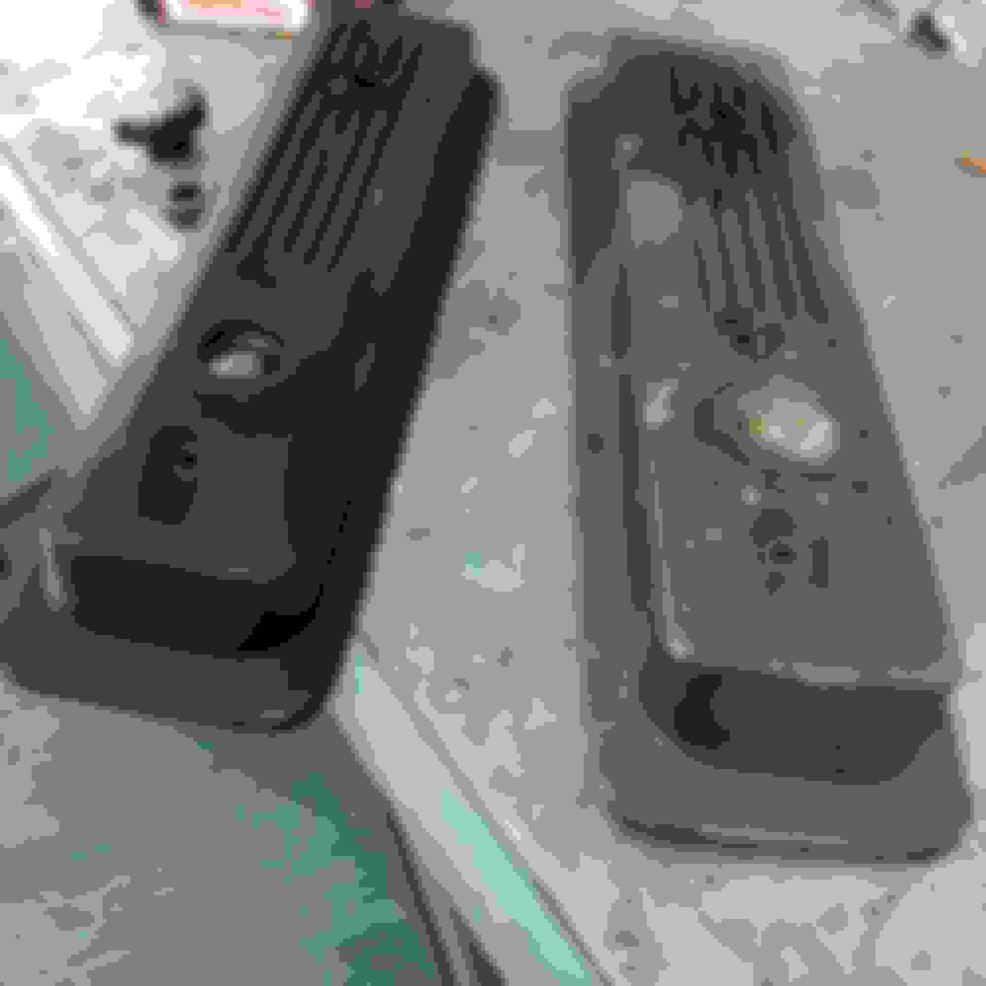
I decided that I wanted to go back to my stock valve covers since I didn't like the look of the current valve covers I had on the engine.
Engine with powder coated GMPP valve covers:
The stock valve covers were taken off many years ago when I got roller rockers, luckily I keep all my original parts... Here's what they looked like:
They were in rough shape, but nothing a little elbow greese couldn't fix!
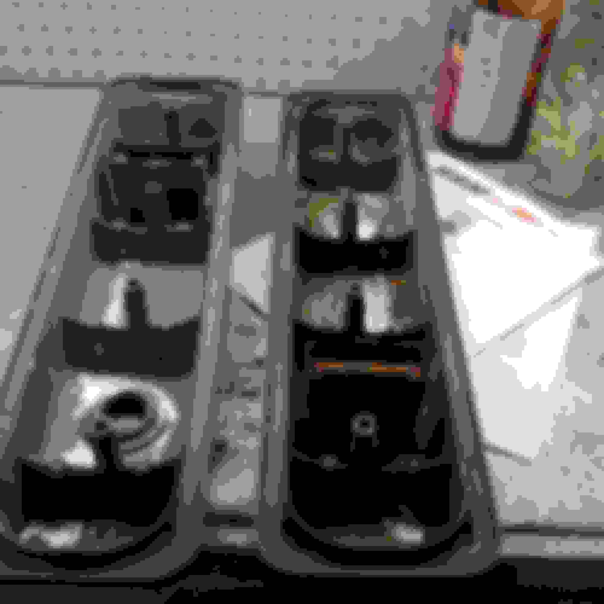
To get the valve covers to fit over my roller rockers I had to grind off the drip rails. The valve covers are made of magnesium so the dust from grinding is flammable so I had to be careful and not let to much dust build up.
The next step was a through cleaning, followed by media blasting:
I could have now painted the valve covers silver as original, but I wanted to go with a different look. So I decided to powder coat them in wrinkle black.
Close up of the finish:
I then added the C4 valve cover logo and my original oil cap:
I then put them on the engine, when I started it up I noticed a slight tapping sound from #8 intake rocker. So I took the covers back off, but I didn't see any signs of rubbing. My guess is that one rocker is just kissing the cover, so I got another set of gaskets and RTV sealed 2 gaskets together on each side then re-installed the valve covers with 'double' gaskets. That seemed to fix the tapping noise.
Here's the vlave covers on the engine:
The PCV I disconnected in the picture because of another project but I'll get to that later.
I didn't quite think the look was complete so I had one more finishing touch to add...
I decided to also go back to the stock IAC cover since I wanted the TPI script. Since I wanted to leave my original IAC cover with my original throttle body in storage I picked up this one from ebay:
To use this cover on my BBK throttle body I had to grind off the tabs on the back side, next I media blasted it:
That was followed by some wrinkle black powder coating:
are they really interchangeable side to side or was the emblem on the passenger side in 88?
Yes, they seem to be interchangeable, I have realized mine are reversed to most corvette's I've seen but the oil fill cap has always been on this side since I got the car so I left it on that side.
As you all may have noticed in the photos of my engine with the valve covers there was no PCB lines hooked up.
That was because I was planning to install a catch can system.
Catch cans are a little more expensive than I was expecting so I decided to use one catch can for both PCB valves.
Here's my Moroso catch can, I mounted it on the engine side of passenger's side wheel well:
I used some 3/8 hose and a couple 'T' fittings to couple all the hoses together. I decided to still run PCB's on both valve covers and use the 'T' fitting to connect them into one hose going into the catch can. There is one hose exiting the catch can and that splits into two hoses that connect back to the TB and intake in the stock location.
Here's some pictures of the system:
The reasons for running a catch can I basically to prevent the engine from sucking an oily mist into the intake, which can cause a number of issues. Using this simple catch can system should prevent those problems.
what are the advantages of an oil catch can vs letting get sucked into the intake?
thnx.
also, ever take your car into the interior at the kelowna track?
There are a couple advantages to the catch can system v.s regular PCV:
-It prevents carbon build up in the intake, heads and combustion camber
-Oil mist on the intake can also contribute to a reduced octane of the air/fuel mixture, which can cause detonation and cause the computer to retard timing which reduces power.
-Using a catch can can also help to extend the life of the O2 sensor and EGR by reducing the chance of them being fouled by contaminates produced from burning excessive oil in the combustion chamber.
I figured for a couple hundred dollars (CAD) for the whole system the benefits seemed worth the cost.
Last edited by DMITTZ; 01-03-2017 at 11:56 AM.
Reason: spelling
 12-31-2016, 02:33 PM