When you click on links to various merchants on this site and make a purchase, this can result in this site earning a commission. Affiliate programs and affiliations include, but are not limited to, the eBay Partner Network.
Not hei.
Ignition circuit means the circuit or circuits that power up when you turn the ignition key to the run position.
Typically this wiring is color coded red on gm vehicles.
Ignition circuit means the circuit or circuits that power up when you turn the ignition key to the run position.
Typically this wiring is color coded red on gm vehicles.
Not so!
OP - What carb? Brand & part #? Most after-market if electric choke is an option offer a kit. If it's snagged from an OE of some sort an attempt at a wiring diagram/function for that OE.
Use an oil pressure switch so choke only operates when engine is running. You can run a fused wire to the from under hood electrical center to one side the other to choke coil.
Use an oil pressure switch so choke only operates when engine is running. You can run a fused wire to the from under hood electrical center to one side the other to choke coil.
GM actually did use a wiring scheme and the OPS. I do think the OP could provide much better/more information.
Oh geez ... you better take another look.
Ignition feed wiring is typically red and battery feed is typically orange. Not always, but when your forced to improvise (like when you put a carb on a fuel injected car) sometimes you have to make decisions that are based on imperfect information.
Oh geez ... you better take another look.
Ignition feed wiring is typically red and battery feed is typically orange. Not always, but when your forced to improvise (like when you put a carb on a fuel injected car) sometimes you have to make decisions that are based on imperfect information.
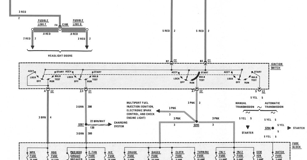
This is a 'typical' ignition switch scheme for early Saginaw column. Anything you see in RED (top) is either a alternator or battery feed. 'imperfect information' - I'd think only supplied by yourself.
Originally Posted by 84 4+3
If you really want to get into it you could probably get the choke light on the warning light panel to come on when it's on too...
This is a 'typical' ignition switch scheme for early Saginaw column. Anything you see in RED (top) is either a alternator or battery feed. 'imperfect information' - I'd think only supplied by yourself.
Go start probing red wiring on your car that is not obviously battery. You will find out that most of them are ignition circuit.
You might as well claim ground circuit wiring is not typically black, turn signals are not green or yellow, solenoid post wiring is not purple ect ...
Last edited by PatternDayTrader; 03-22-2018 at 10:19 AM.
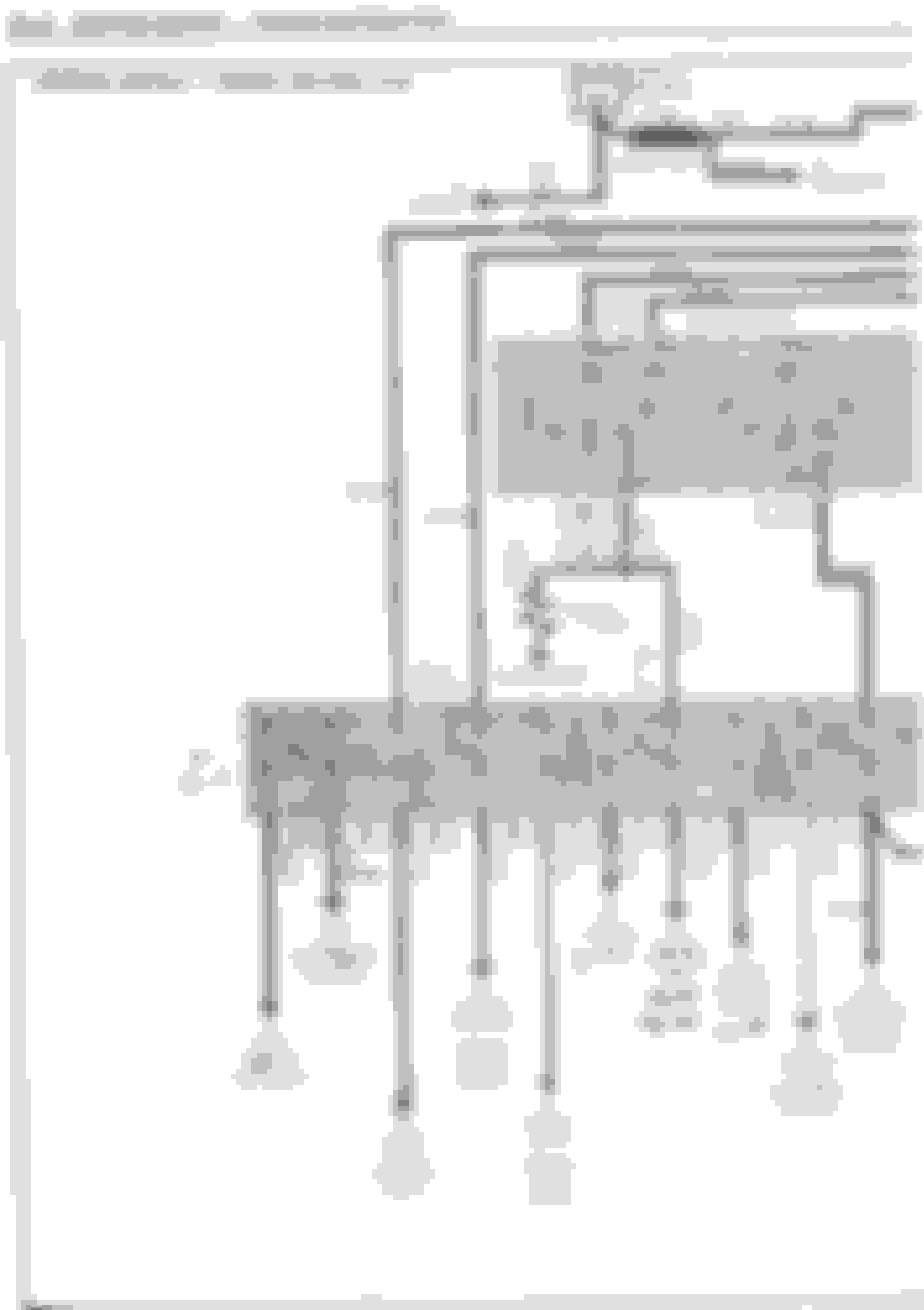
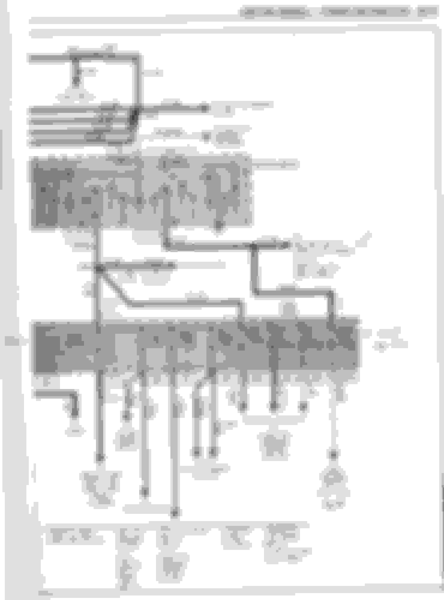
Since the OP has an '84, I thought it might be good to see an '84 Ignition Circuit diagram. (Note the Red wiring.) I'd think a good place to connect that choke wire would be to the fuel pump circuit.
To answer the OP's question, use the pink wire at coil, but use an inline fuse to the choke (placed as close to the coil connection as possible) because the pink wire at the coil is not fuse protected. A short in the choke or wiring will cause the car to quit running when it blows the fuse link. With a 5-amp fuse, the fuse blows, the choke quits, but the car keeps running.
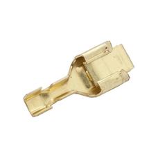
Perhaps the easiest way to accomplish this would be to purchase a Packard 56 terminal (local NAPA or many others), release the terminal
from the connector and crimp the 'new' wire as well as the original wire into the terminal to create the splice.
Thanks everyone for your replies. I learned a lot especially about Packard 56 terminals which I could not find. I took the suggestion of wiring to the batt side of the distributor with an inline fuse. I soldered to the batt wire and covered in heat shrink.


 03-22-2018, 08:31 AM