C4 FRAME TECH. Talk about frame specs and flex solutions...
 02-21-2018, 07:39 PM
#181
Burning Brakes


Maybe there is a way to try to contact Dave McLellen personally? What about Dave Hill? I know he came onboard while they were still developing the C5 but he must have known about the C4's shortcomings and how to correct them or at least how they did correct them. Seems there has to be some way to reach out to these "Corvette pioneers".

 02-21-2018, 07:58 PM
#182


Looking at the spot welds on the 'Vette Kart, it's very believable that the spot welds may weaken, tear, or pop off. I recall reading either earlier in this thread, or in another thread about C4 frames, that someone had found some popped spot welds. The welds aren't very consistent looking to me....eh...why sugar coat it? To me, the welds basically look like ****. 
I don't think the actual frame parts would fatigue in any kind of normal use. My understanding of steel is that there isn't any measurable fatigue until you've bent the metal past it's "plastic deformation" point; the point where you bent it, and it doesn't come back. That isn't happening in the normal flexing of the frame as we operate the car. In normal operation, the frame is acting more like a spring. So, fatigue of the actual rails and steel parts isn't a concern, to me.
What you said about the V2V stiffeners is very interesting to me. I have a theory about that and I've typed it previously on these forum...maybe even in this thread.
My theory is that the stiffeners work by preloading all those crappy spot welds in the rocker rail, so they can't flex; they're already flexed as much as they can tolerate (roughly)....thereby making the car feel stiffer. I theorize that you notice an immediate gain in ride quality (chassis stiffness), upon installation and preloading of the frame, but that it may "pull"/tear the spot welds over time, as you have it preloaded, then hit bumps, potholes, etc. The stresses on those spot welds would be huge, IMO, once you've tensioned the bars...then go drive it where it has not choice but to flex -even with the bars trying to force it not to.
Your observations seem to align with my theory. Which is a bummer, if true.
The problem w/the V2V system is that it's not adding strength to the car; it's preloading spot welds. A true, weld in subframe connector would add real strength, AND some rigidity...while not adding loads to the frame rails.
.
02-21-2018, 09:10 PM
#183
Safety Car

Tom's theory is pretty sound. It would be interesting to be able to figure the tension being applied to the pieces of metal that are spotted welded together and see which way that they are trying to move as the car is going through flexion, contraction and torsion as the car moves down the highway.
That could account for the popped spot welds, the 2 pieces trying to go in opposite directions.
Here in NE Ohio where the roads are notoriously bad, that could kill a car pretty quickly. I have been known to drive 7 or more miles out of my way just to avoid the bad roads and have meticulously figured out the smoothest way to drive to the places we usually go when out in the car.
I left the car sitting out in the sun one day and it heated up pretty hot. When I pulled up out of the driveway, I could actually hear the top rattling until the car cooled back down. It was pretty weird.
I think I read about it on one of the posts here on the forum that someone cutout areas if the first layer of metal and then welded the 2 pieces together (or something like this) to strengthen up the areas that are accessible to reweld.
02-22-2018, 02:41 PM
#184
Team Owner

Pro Mechanic
Thread Starter
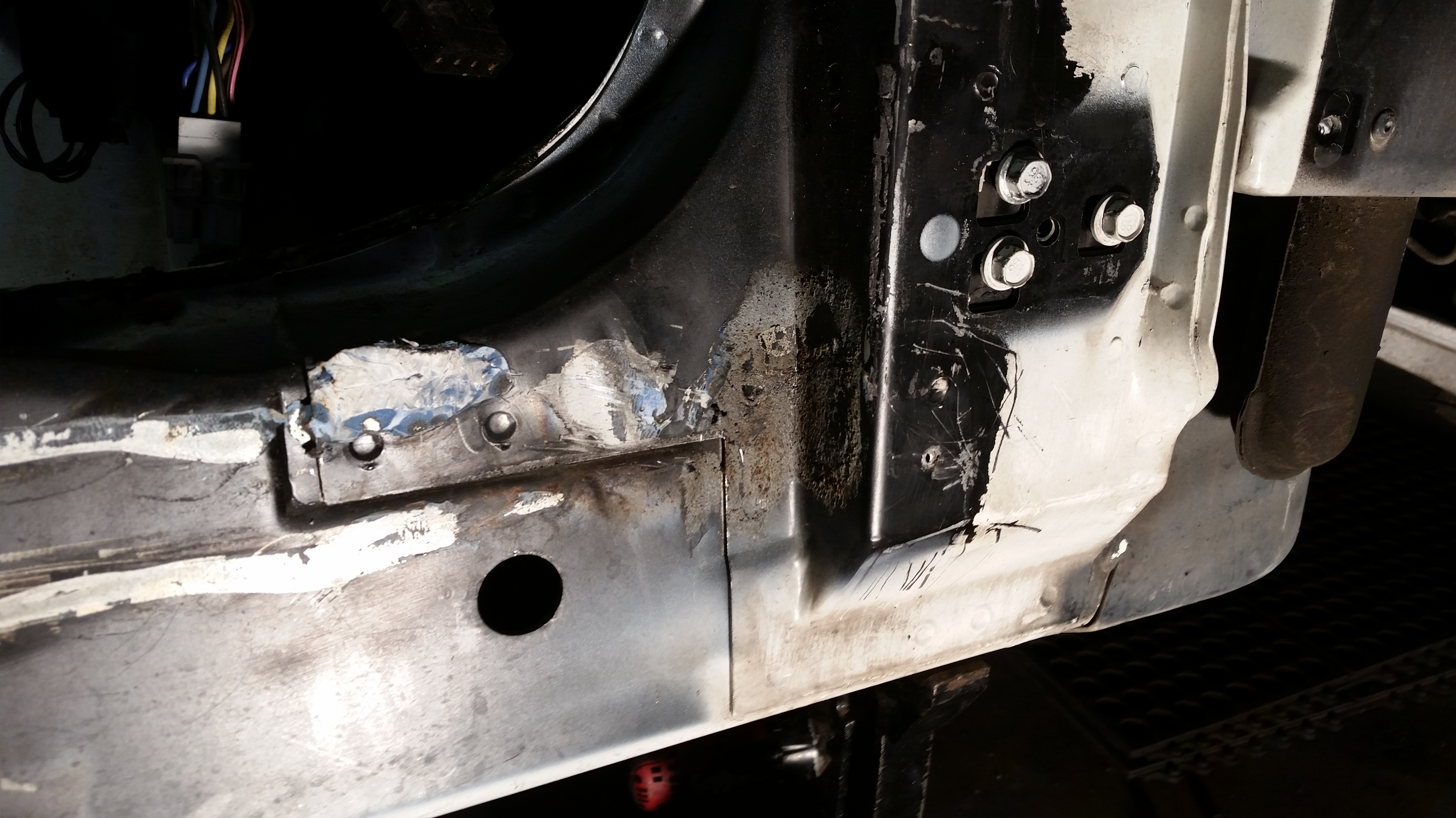
I decided to go take some pics of the Kart, to show how janky the connecting points of the frame rail pieces are.
Here is the front of rocker, to door post...
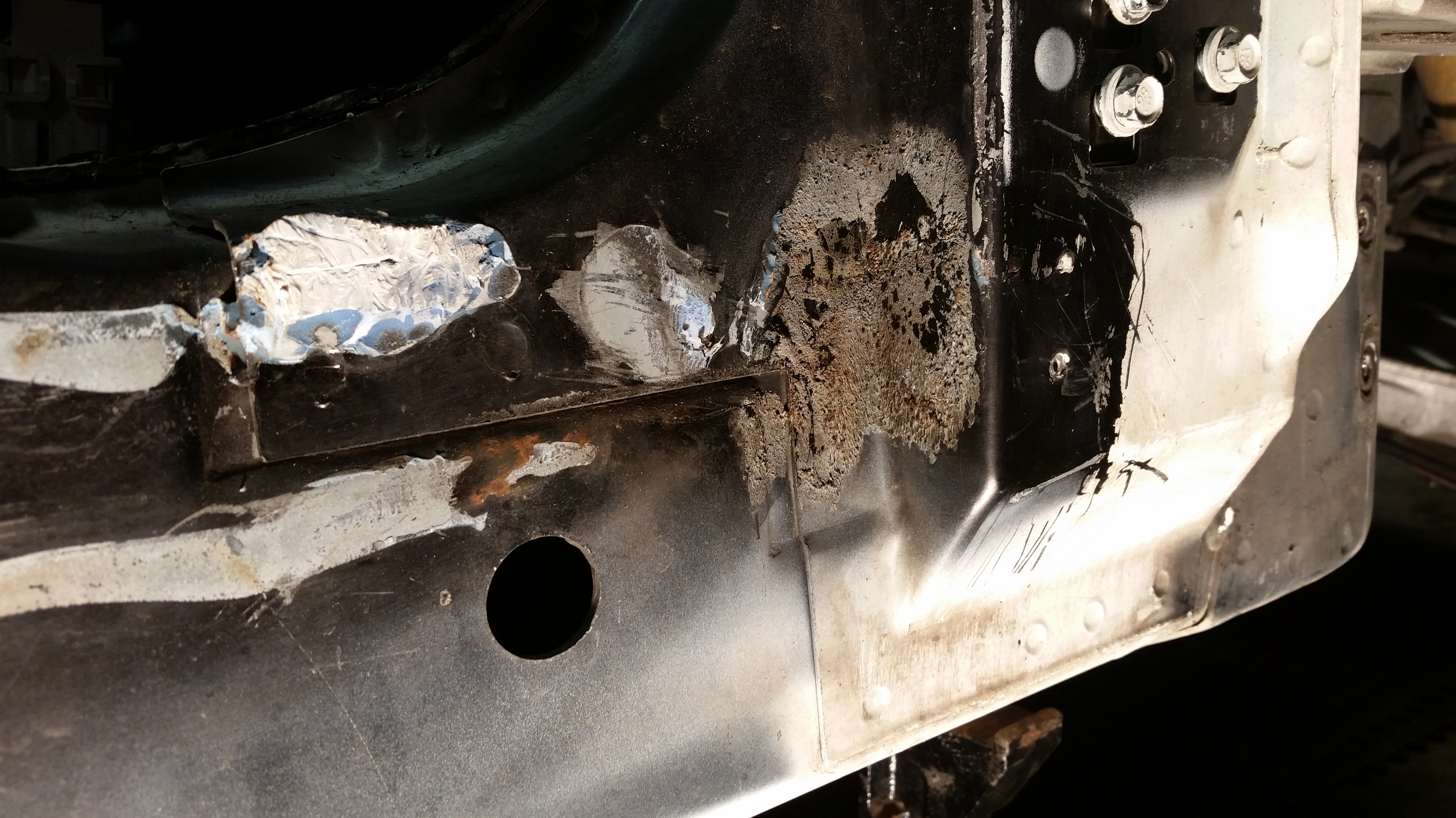
Here is the "front end", of the rear of rocker, to "rear of car" (?) or the b-pillar segment...
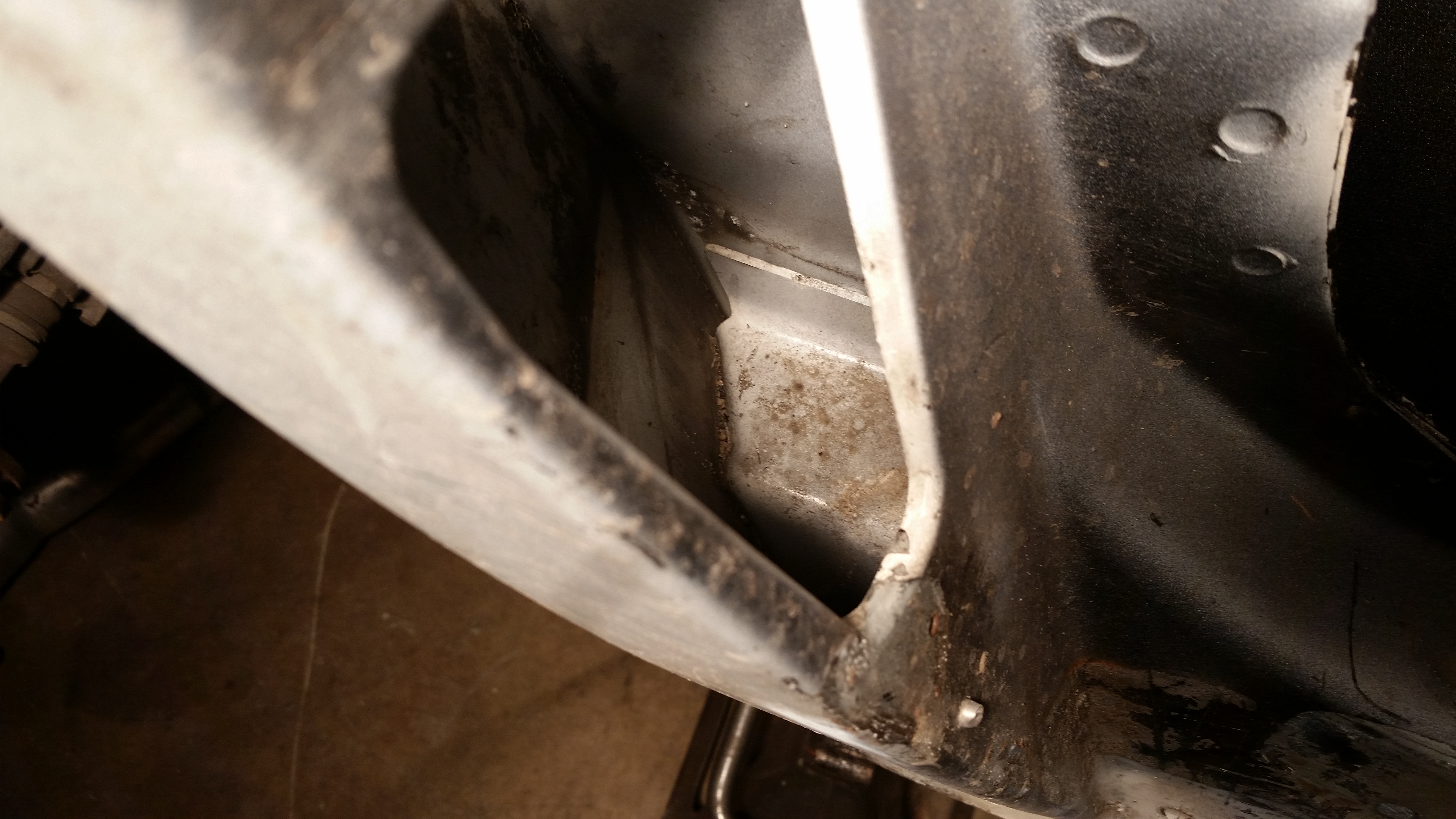
What we're looking at here is the forward edge of a gusset that help stabilize the door post. The thing isn't even touching the frame rail! And look at the welds...a couple goobs in some slots?? Why didn't they weld around the whole flange? Hoakie.
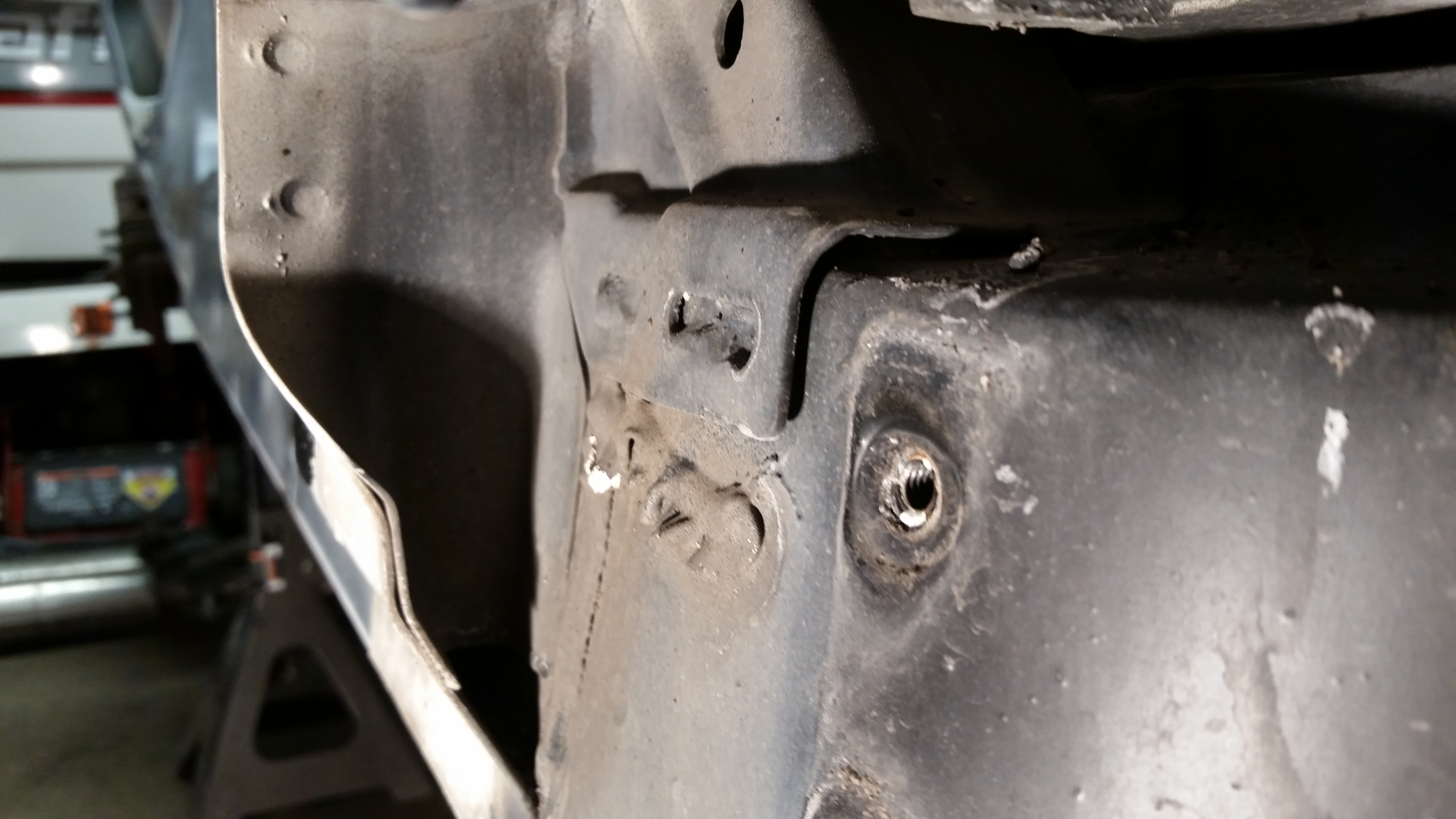
Here in the back, this is looking down through the cabin exhaust vent hole (below where the door striker is). You can see the box tubing that is the continuation of the rocker frame rail into the b-pillar segment...not a single weld connecting it to the rear of car in there...in fact, there is quite a gap between the two pieces of metal.
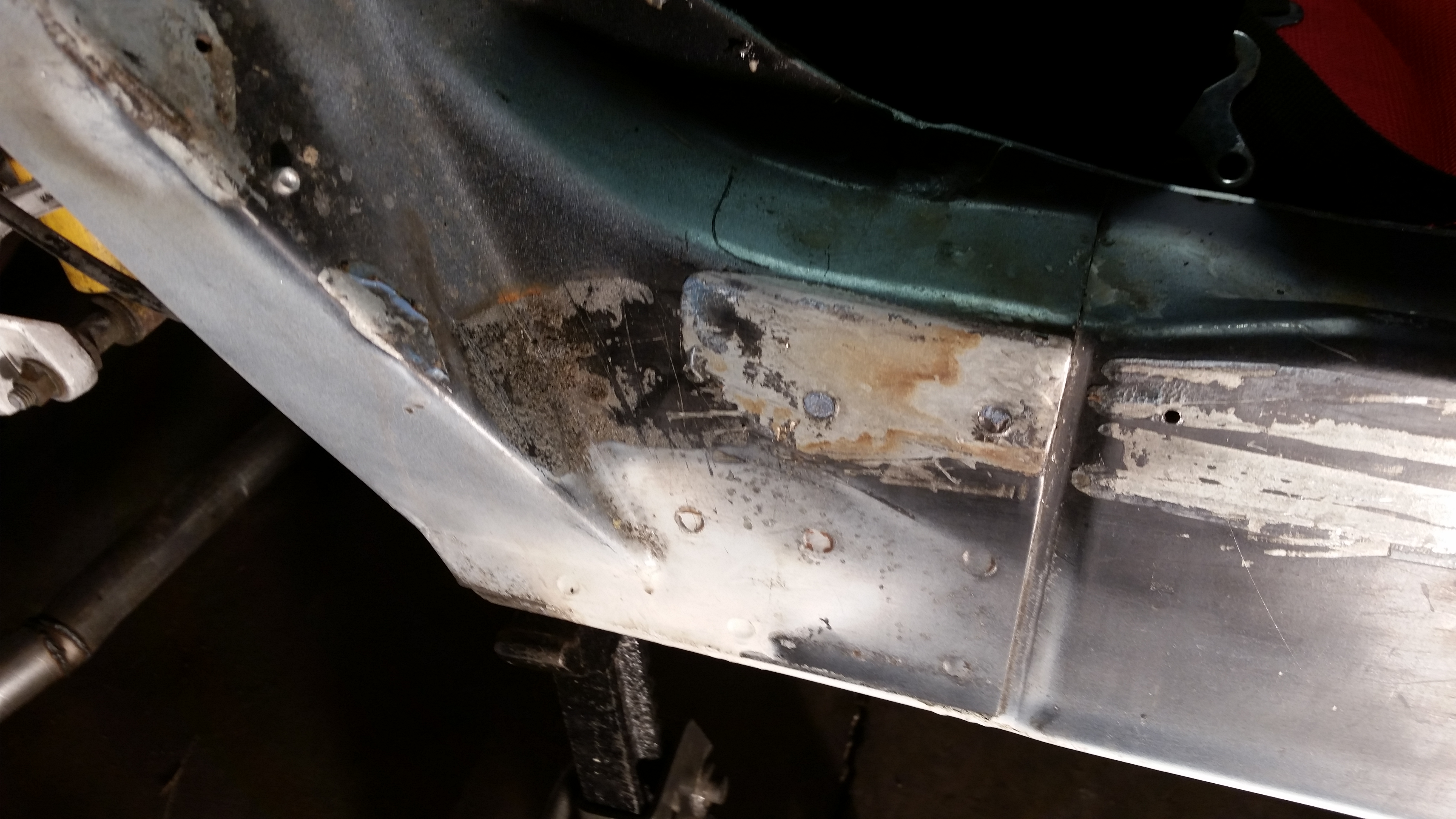
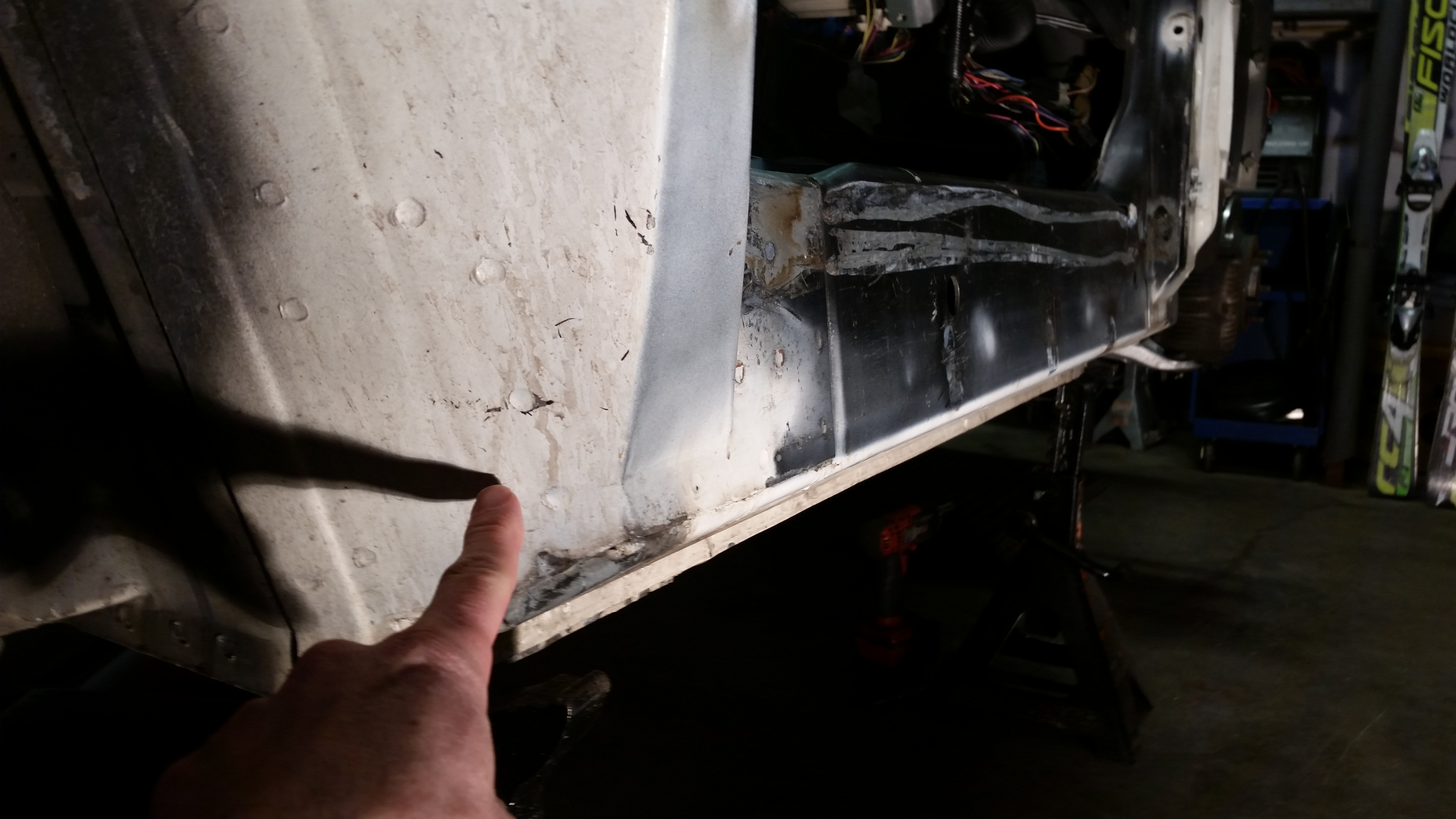
So this is how they attached the rest of the rear of rocker rail to rear of car; a smattering of spot welds, where the rear end of the rocker rail butts up against that tin. I'm pointing at the spot where I'd make a hole for the tube steel addition I've been pondering.
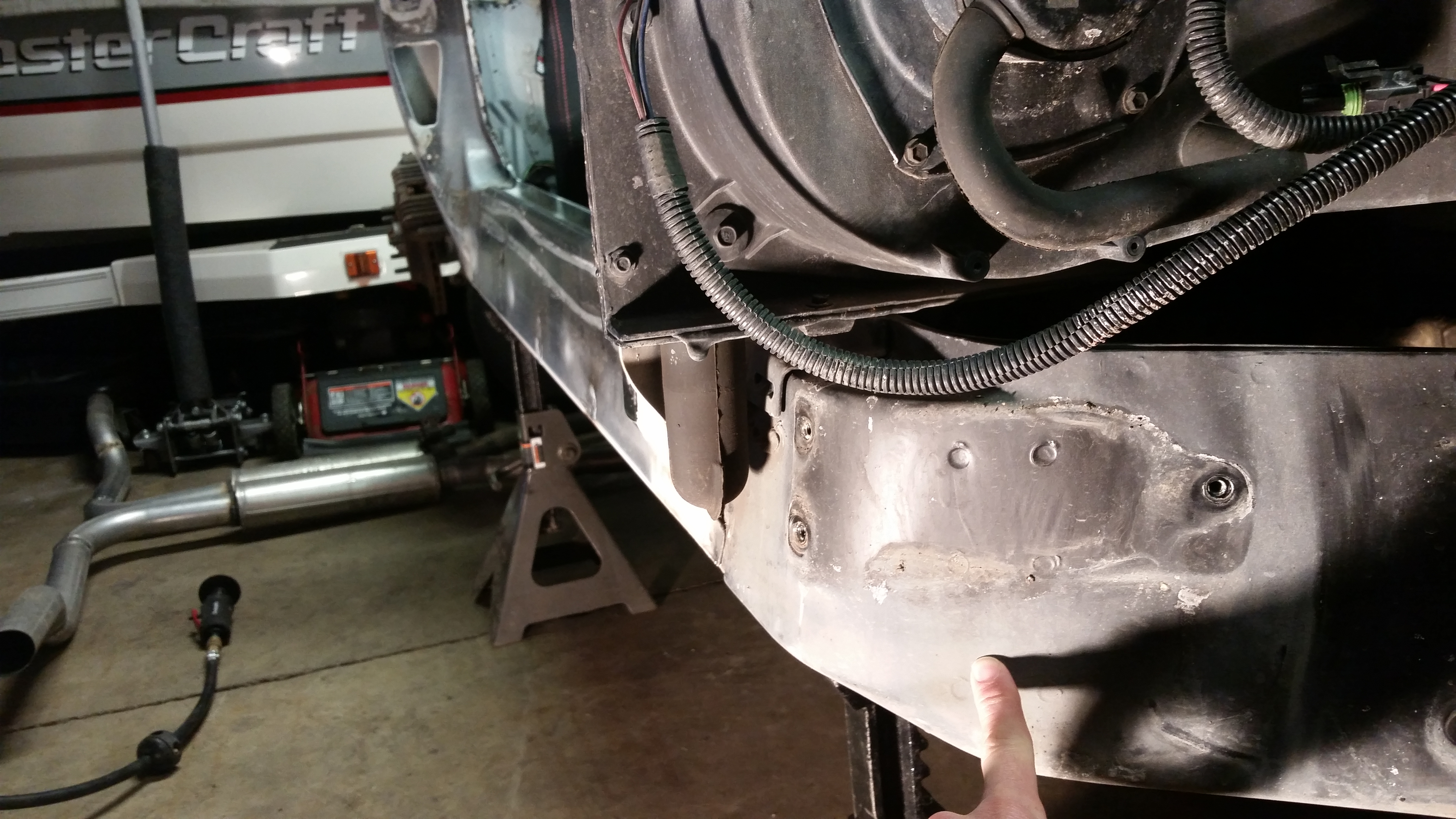
Here is the front spot where I'd make a hole, to slide the pipe into, then cap and tie into that curved/vertical part of the frame.
.
Last edited by Tom400CFI; 02-22-2018 at 03:25 PM.
02-22-2018, 06:09 PM
#185
I decided to go take some pics of the Kart, to show how janky the connecting points of the frame rail pieces are.
Here is the front of rocker, to door post...
Attachment 48257600
Attachment 48257606
Here is the "front end", of the rear of rocker, to "rear of car" (?) or the b-pillar segment...
Attachment 48257601
What we're looking at here is the forward edge of a gusset that help stabilize the door post. The thing isn't even touching the frame rail! And look at the welds...a couple goobs in some slots?? Why didn't they weld around the whole flange? Hoakie.
Attachment 48257605
Here in the back, this is looking down through the cabin exhaust vent hole (below where the door striker is). You can see the box tubing that is the continuation of the rocker frame rail into the b-pillar segment...not a single weld connecting it to the rear of car in there...in fact, there is quite a gap between the two pieces of metal.
Attachment 48257607
So this is how they attached the rest of the rear of rocker rail to rear of car; a smattering of spot welds, where the rear end of the rocker rail butts up against that tin. I'm pointing at the spot where I'd make a hole for the tube steel addition I've been pondering.
Attachment 48257602
Here is the front spot where I'd make a hole, to slide the pipe into, then cap and tie into that curved/vertical part of the frame.
Attachment 48257603
.
 The metal looks pretty strong but the welds are junk. Do you think just MIG welding the joints would be enough to take care of the flex (not that this is very doable for those of us with body panels)?
I like the idea of installing the pipe through the frame and then welding it in. I imagine doing both would create a pretty stiff frame.
02-22-2018, 06:21 PM
#186
Melting Slicks

Those are some of the worst fitting parts I have ever seen. The frame such as it is looks to made out of light ga. sheet metal that is spot welded here and there at best. It would have been much better with a one piece stamping like a unibody car. If any of this was run through finite analysis it was done with the assumption the rails and other parts were all one piece and no gaps in the stampings along with no spot welds just one solid part. The targa top would certainly help but not the final answer. I am not sure this frame could pass tech in a lawn mower race.
02-22-2018, 06:27 PM
#187
Team Owner
Pro Mechanic
Thread Starter
Grandspt, You're welcome. I enjoy studying this.
I agree. The parts/design doesn't seem bad to me...the execution seems pretty terrible.
I do think that MIG welding up those seams -especially those around the Door post and B-pillar that I took pics of. When I flex the chassis by hand, it seems like most of the flex is at that front rocker rail to door post point.
One thing I learned when disassembling the Kart was that heat is your friend, removing the FRP panels that are glued on (like the door sill panel). When I tore the body apart, some panels came off fairly easily w/o heat -they came off w/o breaking at least....but other parts simply fractured and broke. Later, when I was scraping the glue off the frame, I learned about the heat, and then the glue would just peel away effortlessly with a putty knife where when cold, I'd have to us a chisel and hammer. Knowing what I know now, I believe that you could heat the steel rocker rail up good and hot, then peel the FRP sill off w/o damaging it. Weld your frame, and glue it back on.
.
If I'm going to try the pipe, I need to do it before I weld the frame seams. Otherwise I won't know the diff the pipe makes. But I do intend on welding the frame either way.
Last edited by Tom400CFI; 02-22-2018 at 06:31 PM.
02-22-2018, 06:31 PM
#188
Team Owner
Pro Mechanic
Thread Starter
Those are some of the worst fitting parts I have ever seen. The frame such as it is looks to made out of light ga. sheet metal that is spot welded here and there at best. It would have been much better with a one piece stamping like a unibody car. If any of this was run through finite analysis it was done with the assumption the rails and other parts were all one piece and no gaps in the stampings along with no spot welds just one solid part. The targa top would certainly help but not the final answer. I am not sure this frame could pass tech in a lawn mower race.
02-22-2018, 07:28 PM
#189
Race Director


I agree. The parts/design doesn't seem bad to me...the execution seems pretty terrible.
I do think that MIG welding up those seams -especially those around the Door post and B-pillar that I took pics of. When I flex the chassis by hand, it seems like most of the flex is at that front rocker rail to door post point.
I do think that MIG welding up those seams -especially those around the Door post and B-pillar that I took pics of. When I flex the chassis by hand, it seems like most of the flex is at that front rocker rail to door post point.
I'm sure lots of you guys have seen the high-end "HOW THEY DO IT?" car building shows. Some glue and weld joints. Is it possible those joints are glued too?
It's hard to tell how much "penetration" the side rail has into the lower front A-pillar area....but I'll go off your observations that most of the flex occurs there AND that the V2V stiffener may actually target that?
Looks like a fun project. How you feel better soon!
02-22-2018, 07:37 PM
#190
Team Owner
Pro Mechanic
Thread Starter
Thanks!
The V2V bars "pull", or try to compress the entire rocker assembly.
The V2V bars "pull", or try to compress the entire rocker assembly.
02-22-2018, 10:11 PM
#192


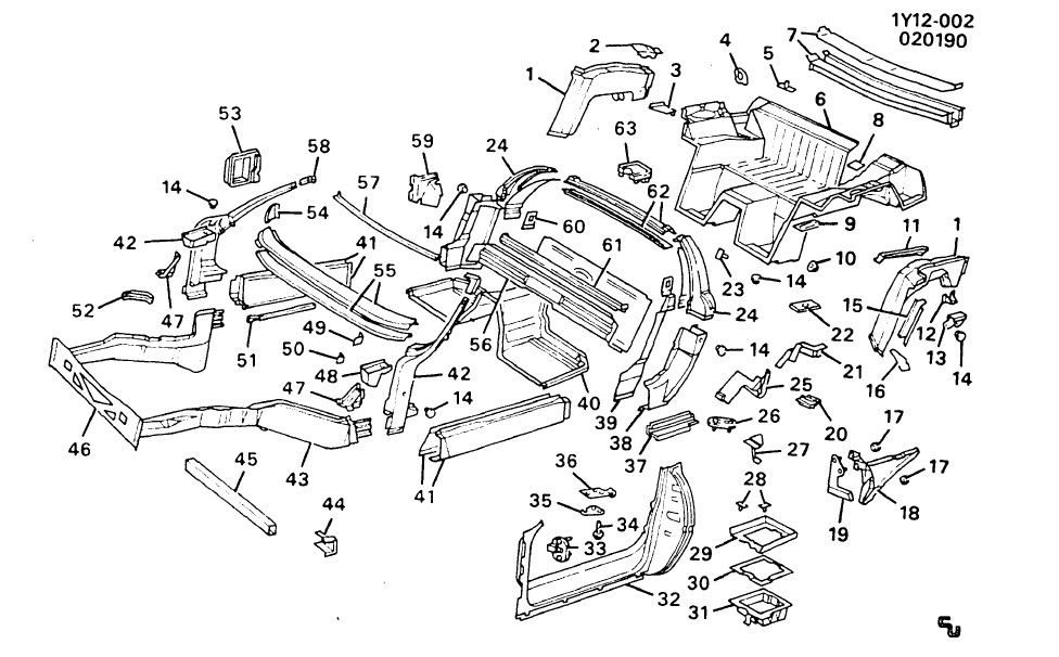
If the HSLA (High strength Light Alloy) rails are as poorly done as you hint the SMC panels 'on all cars' would be just a mass of splinters and crazing through the finish. That is very seldom ever seen. You would actually have to drill and remove all of the spot welds to actually diagnose the efficiency of the assembly process. The SMC actually adds substantially to the build. Removing the SMC as in your 'kart' results of course in a lesser product. A typical cage would certainly improve 'the kart'. I didn't read the entire thread (didn't see the need).
Someone commented about 'unibody' - this is very close to nearly identical. There's very little that's different.
You can maybe sort the HSLA structure from this 'typical' coupe structure. Note the gussets etc.
Someone commented about 'unibody' - this is very close to nearly identical. There's very little that's different.
You can maybe sort the HSLA structure from this 'typical' coupe structure. Note the gussets etc.
Last edited by WVZR-1; 02-22-2018 at 10:16 PM.
 02-22-2018, 11:19 PM
#193
Team Owner
Pro Mechanic
Thread Starter
I don't agree with this at all. The FRP is thin, light...and very flexy/flimsy. It has no strength and adds no strength in any meaningful way. No, the car lost nothing but weight by removing the FRP.
02-23-2018, 12:37 AM
#194
Race Director
Of course, I also have to consider the significant number of people wanting a more rigid chassis AND that manufacturers strive exactly FOR that! We know bridges and other major structures MUST flex to avoid breakage but they aren't suspended on the same level of articulating suspension. So...I'm forced to look at what other manufacturers tout...that a stiffer frame IS better.
I remember reading out X-braces AND McLellan's different solution. Maybe it's earlier in this thread: Which was considered "better"? Was EITHER considered "good"? Probably not since the C5 used a different approach to address structural rigidity. And, since builders of the C4 explicitly stated their original structure design didn't foresee the inclusion of a targa or vert.
Kinda reminds me of something I did last year. I removed a support post between the transition of my entry way and family room. [It was obnoxious] I felt the rest of the structure would keep anything from severely sagging/falling. Specifically, the header I found OVER the severed post comes close to online framer's charts for the span in question. (I would have needed to pull drywall and expose more of the frame to analyze further....Naw...Not going to tear up THAT much!)
After discussion with a contractor, engineer, and DIYer friend, I went for it. I left the post out and decided it wasn't "critical" to success/failure. GM probably decided the same thing here. Both can be considered "functional" as-is. Maybe not "ideal", but functional.
Ok...OK...some blabbering going on here. I guess I'd want to see someone push down on the RR of their full-bodied Corvette -- using the same technique as Tom. We all KNOW it wouldn't flex as much.
Right?
02-23-2018, 01:41 AM
#195

 02-23-2018, 01:49 AM
#196
Race Director

 02-23-2018, 01:54 AM
#197
We can also ask Tom to put the door back on and see what the halo/a pillar does, because in my mind I figure that probably would help the most, not taking 1st place from the targa.
So are we down to arguing if the door sills matter, and the floorboard?
How are the rocker panels (body)attached?
I may sound like but I am serious.
I had the hood close and latch, with my hand stuck in there. I had the pleasure of staring at the SMC flex around my nuckles while I yelled for my buddy to unlatch it. The car does flex really good. And yes it hurt.
So are we down to arguing if the door sills matter, and the floorboard?
How are the rocker panels (body)attached?
I may sound like
but I am serious.I had the hood close and latch, with my hand stuck in there. I had the pleasure of staring at the SMC flex around my nuckles while I yelled for my buddy to unlatch it. The car does flex really good.
And yes it hurt.
02-23-2018, 01:55 AM
#198
No, I know mine does not. It is also special, and I have some sort of door issue on the passenger side not wanting to shut. Currently it is making a nice storage unit, since life has been so kind to me. Otherwise I would be out with a laser, plumb bob, and jack messing with the chassis.
02-23-2018, 08:21 AM
#199
Safety Car
My friend here in Ohio has a 1990 coupe. He jacked it up on the jacking point on the left side. It flexed the chassis so much, the hood moved and had to be readjusted. He didn't pop the hood or open the doors though.
GM has screwed up a lot in unibody/frame analysis. I had a 1980 Z28 with T-tops. It popped the windshield loose. If you jacked it up using the supplied bumper jack at the front, both doors would open on their own (actually swing open).
The body shop manager told me that I should just get rid of it because a frontal collision would slam the windshield back into the cockpit.
The neighbor kid had a 1979 Z28 with T-tops. He hooked it up one night and when it grabbed traction, the body corkscrewed so bad, the paint across the roof lifted off.
I learned how to tell the ones that had been bent, there was litte V crimps on the back pillars.
02-23-2018, 08:28 AM
#200
Le Mans Master

When the frame of the C4 flexes in torsion, the targa roof panel is loaded in shear. The metal frame by itself wouldn't do much to add stiffness - it would distort like a parallelogram. It requires the clear panel of plastic to act as a shear web in order to provide much stiffness to resist the shear loads. Think of a shear web as the same idea behind the middle part of an "I" beam: it doesn't have to be strong in any other direction except shear loading.
I could be missing something, but I don't see how the doors are going to add much stiffness. They have two front hinges with at least a little slop, and basically no solid attachment at the other end. If your door's edge is contacting anything other than the pin that the mechanism latches onto, then it will rub and mess up the paint and not close properly. If it has no solid attachment at one end, it can't provide significant resistance to distortion in any plane. Note that the targa top, in contrast, is bolted in solidly.
ETA: LOL at Dr. Cook's reminiscing about F-bodies. I had a 2nd-gen and a 3rd-gen, and the 2nd-gens were the worst at torsional stiffness of any car I've ever worked on. The 3rd-gens were an improvement, but still pretty susceptible to permanent deformation. I think the last couple eyars, where they added some form of adhesive bonding to a lot of panels, made a real improvement. I wonder if the same is true of C4s. My 96 is not nearly as flexible as your friend's 90. I jack it from either rear/side jacking point all the time, and never have issues. I've never tried it with the roof off, though. That said, we have to remember that the C4 was basically a 1980 design in terms of analysis technology. All cars of that era were vastly inferior to modern designs in terms of frame stiffness. The 911 Targa of that era was jokingly called the "flexible flyer" for the same reason. It wasn't just GM that hadn't grasped the importance of torsional rigidity. Of course, back then spring and damping rates were generally a lot lower, tire sidewalls were more compliant, and tires had a lot less grip. So the need was somewhat less than it is now, too.
Last edited by MatthewMiller; 02-23-2018 at 08:35 AM.
The following users liked this post:
Red 91 (02-23-2018)