TDC & Relationship to Crankshaft Hub
 12-07-2010, 11:38 AM
#1
Advanced

Thread Starter


Okay. . .
I'm done with the work that I've posted under different "covers", but here is something that didn't jump out in my search of the forums. This is for those that have been "blessed" with the OptiSpark as their distributor & cap (depating from the traditional type we are familiar with).
Here's my issue:
I've got the new cam gear and chain in place with the "dots" aligned properly. In order to do this the crankshaft had to be turned. This moved my earlier point of reference (mark) when I removed the harmonic balancer & crankshaft hub.
Now that I have THOSE lined up, I see the groove in the new OptiSpark unit I have and the corresponding notch in the camshaft gear (of course you only can see this BEFORE you put the timing gear cover back on).
So is THIS top-dead-center (TDC for those without 'hymnals')???? The SManual only states to "find TDC, install hub with mark up".
I know this has been covered SOMEWHERE in a thread, but it might need its own thread. Or my lame search didn't find it, so a pointer would be appreciated.
Thanks in advance for pointers & input.
 12-07-2010, 12:15 PM
#2


Okay. . .
I'm done with the work that I've posted under different "covers", but here is something that didn't jump out in my search of the forums. This is for those that have been "blessed" with the OptiSpark as their distributor & cap (depating from the traditional type we are familiar with).
Here's my issue:
I've got the new cam gear and chain in place with the "dots" aligned properly. In order to do this the crankshaft had to be turned. This moved my earlier point of reference (mark) when I removed the harmonic balancer & crankshaft hub.
Now that I have THOSE lined up, I see the groove in the new OptiSpark unit I have and the corresponding notch in the camshaft gear (of course you only can see this BEFORE you put the timing gear cover back on).
So is THIS top-dead-center (TDC for those without 'hymnals')???? The SManual only states to "find TDC, install hub with mark up".
I know this has been covered SOMEWHERE in a thread, but it might need its own thread. Or my lame search didn't find it, so a pointer would be appreciated.
Thanks in advance for pointers & input.
I'm done with the work that I've posted under different "covers", but here is something that didn't jump out in my search of the forums. This is for those that have been "blessed" with the OptiSpark as their distributor & cap (depating from the traditional type we are familiar with).
Here's my issue:
I've got the new cam gear and chain in place with the "dots" aligned properly. In order to do this the crankshaft had to be turned. This moved my earlier point of reference (mark) when I removed the harmonic balancer & crankshaft hub.
Now that I have THOSE lined up, I see the groove in the new OptiSpark unit I have and the corresponding notch in the camshaft gear (of course you only can see this BEFORE you put the timing gear cover back on).
So is THIS top-dead-center (TDC for those without 'hymnals')???? The SManual only states to "find TDC, install hub with mark up".
I know this has been covered SOMEWHERE in a thread, but it might need its own thread. Or my lame search didn't find it, so a pointer would be appreciated.
Thanks in advance for pointers & input.
Depends on what you mean by having the cam and crank gear dots aligned "properly", since it can actually be done two ways and both are correct.
Many prefer to align the gears by having the crank gear dot at 12 o'clock and the cam gear dot at 6 o'clock and that is fine except it is actually TDC for number 6 cylinder. To insure you are at TDC for number one the cam and crank gear dots must both be at 12 o'clock. The opti will only install one way assuming you don't force the spline on the early style.
12-07-2010, 01:39 PM
#3
Advanced
Thread Starter
"Properly" was as described in the SManual. What they DON'T say are the things that the great folks HERE tell you--THANKS 'toptechx6' for the hint/pointer. Since I do, indeed have the cam/crank gears aligned at the 6 & 12 o'clock "dots", respectively, this is how the SM states.
Of course it DOES mention that if the crank was moved after "marking" the position it (crank hub) was removed, that you can re-install the hub and balancer (with THEIR marks aligned) with the engine at the TDC.
Now for the follow-up. Once I move the crank/cam to the opposite positions from above (that is, move the cam/crank to 12 & 6 o'clock, respectively), will this be TDC on the "fire" turn of the crank????
I don't have the valve covers off to assure that the pressure is off the #1 cylinder (and don't want to take them off if I can avoid yet another part on the floor), so this is an important point.
ONCE this is set up, one can be more assured about putting the timing cover back on, then the OptiSpark, water pump, et cetera.
Additional input/clarification so this sinks in before I proceed?
Thanks in advance.
toptechx6
Depends on what you mean by having the cam and crank gear dots aligned "properly", since it can actually be done two ways and both are correct.
Many prefer to align the gears by having the crank gear dot at 12 o'clock and the cam gear dot at 6 o'clock and that is fine except it is actually TDC for number 6 cylinder. To insure you are at TDC for number one the cam and crank gear dots must both be at 12 o'clock. The opti will only install one way assuming you don't force the spline on the early style.
 12-07-2010, 02:58 PM
#5
Advanced
Thread Starter
Arrr mate. . .
But me worries are with the crankshaft hub and harmonic balancer "markings" in RELATIONSHIP to the engine and TDC. I've got a partial answer from 'toptechx6', but wanted a follow-up to that. My question/followw-up was:
"Now for the follow-up. Once I move the crank/cam to the opposite positions from above (that is, move the cam/crank to 12 & 6 o'clock, respectively), will this be TDC on the "fire" turn of the crank????"
Of course the above might not be fully comprehensable unless my entire previvous thread was read discussing the alignment of the "dots" on the cam & crank gears.
It would be REAL easy if the crank hub had a keyed slot like the crank GEAR does.
Thanks again ya all.
12-07-2010, 03:15 PM
#6
Arrr mate. . .
But me worries are with the crankshaft hub and harmonic balancer "markings" in RELATIONSHIP to the engine and TDC. I've got a partial answer from 'toptechx6', but wanted a follow-up to that. My question/followw-up was:
"Now for the follow-up. Once I move the crank/cam to the opposite positions from above (that is, move the cam/crank to 12 & 6 o'clock, respectively), will this be TDC on the "fire" turn of the crank????"
Of course the above might not be fully comprehensable unless my entire previvous thread was read discussing the alignment of the "dots" on the cam & crank gears.
It would be REAL easy if the crank hub had a keyed slot like the crank GEAR does.
Thanks again ya all.
But me worries are with the crankshaft hub and harmonic balancer "markings" in RELATIONSHIP to the engine and TDC. I've got a partial answer from 'toptechx6', but wanted a follow-up to that. My question/followw-up was:
"Now for the follow-up. Once I move the crank/cam to the opposite positions from above (that is, move the cam/crank to 12 & 6 o'clock, respectively), will this be TDC on the "fire" turn of the crank????"
Of course the above might not be fully comprehensable unless my entire previvous thread was read discussing the alignment of the "dots" on the cam & crank gears.
It would be REAL easy if the crank hub had a keyed slot like the crank GEAR does.
Thanks again ya all.
When they are aligned at 12 and 6 #1 piston is also at the top but it is on the exhaust stroke.
12-07-2010, 03:15 PM
#7
Melting Slicks


when the crank at number one is at TDC (doesn't matter if at TDC compression stroke or TDC exhaust stroke) the little triangle on the hub should point straight up
12-07-2010, 03:18 PM
#8
Race Director

OK, align your timing gears dot-to-dot, reinstall the timing cover, and reinstall the balancer and hub so the balancers timing mark is at 12:00. You will now have TDC for #1 and #6 cylinders marked.
12-07-2010, 03:29 PM
#9
Former Vendor

Member Since: Oct 2006
Location: Waukesha Wisconsin
Posts: 134
Likes: 0
Received 0 Likes
on
0 Posts
12-07-2010, 03:45 PM
#10
Race Director
 j/k Got any pics of what they look like?
When reinstalled the LT1 balancer's timing mark is nearly impossible to see. I use a paint pen on the outside of the balance at this mark for future references.
12-07-2010, 04:17 PM
#11
Advanced
Thread Starter
I would only have the picture of the timing mark(s) of the cam/crank gears.
Yeah 'Chandler'...THAT would be nice with the aftermarket, but I'm on the low income diet of parts acquistion. I'm sure a fully balanced "balancer" and hub might run a bit more than this project's budget.
'STL94LT1' is making sense to me when combined with the others (below) when he says: "
OK, align your timing gears dot-to-dot, reinstall the timing cover, and reinstall the balancer and hub so the balancers timing mark is at 12:00. You will now have TDC for #1 and #6 cylinders marked"
I just don't want to have to take off the timing cover and need the 'warm fuzzies' to make sure these marks on "ready to roll" once I bolt that timing cover on. Does this apprehension make sense??? I've read too many threads in this forum where the due diligence wasn't made up front and another tear down was required.
It makes sense what 'mtwoolford' & 'toptechx6' are saying below--please correct me if I'm mistaken here, but for every TWO turns of the crank (one turn for intake, another for exhaust stroke) the cam will turn over ONCE. Is this correct "theory"?
12-07-2010, 04:52 PM
#12
Race Director
To double check have the timing marks aligned dot-to-dot, rotate the engine until they come back together. If they are still aligned, the timing cover is ready to be installed.
12-07-2010, 05:02 PM
#13
Le Mans Master

According to my 96 Factory Service Manual, the #1 piston has to be at TDC when the hub is installed. It doesn't matter (and no mention is made in the FSM) where the #1 position is on the Compression or Exhaust stroke.
Once the #1 piston is at TDC, the hub is then installed with the indicator mark - a little triangle - placed at the 12 o'clock position.
Although I've seen posts that claim it doesn't matter where the #1 piston is positioned or where the little triangle is positioned, GM doesn't agree and lists the specific way the re-installation should be done.
There's also a specific procedure for installing a new/replacement GM pulley/balancer. Many may not realize it but there's a weight in the pulley/balancer that has to be swapped and correctly positioned in the new/replacement. pulley/balancer.
It's not a "theory", it's a fact. The crank turns TWICE (720 degrees of rotation) for each ONE turn (360 degrees) of the cam.
Good to see you're paying attention to the details. Far too many don't.
Jake
12-09-2010, 11:50 AM
#14
Advanced
Thread Starter
Alrighty gents. . .
This is still bothering me, so before putting this whole thing together I've done all that is recommended precautions in this thread.
- turned crank over to align the dots once again (crank dot @12, cam dot @6)

- was ready to install timing cover, but wanted to "map" where the rotor would be
Sooooo. . .
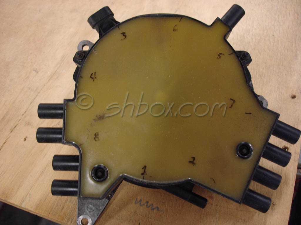
This is the bothering part--WHERE in the heck is the #1 place on the distributor/opti "cap"??? Yes, yes. . . the OUTSIDE is marked where the secondary plug wires go, but which point/contact on the inside maps to the marks 1, 7, 3,5 & 2, 8, 6, 4??
See my pictures below. The first picture is how the opti looks on the cleaned timing cover outside of the car. Hopefully you all can see the numbers as they appear printed on the outside of the Opti.

Take the cover off and it looks like below. Renumbered to show the reverse/flip of the cover. Anyone care to fill in the blanks??? :

My first question: WHICH point (inside opti cover) maps to which optispark point where the secondary wires would be connected? The reason this is somewhat confusing, is by looking at the inside of the "cap", it is not so clear as to which is #1 cylinder. Thus, I've placed pictures below for the opti to simulate separate scenarios:
1. "Dots" on cam/crank alighed: Cam gear in 6 o'clock position, crank @ 12 o'clock
2. "Dots" aligned with Cam gear at 12 o'clock, crank @ 12 o'clock
Survey of the forum readers out there--WHICH picture below (A or B) match the above scenarios??? That is, WHERE should the rotor be pointing to the #1 cylinder inside the optispark to be firing at TDC???
Picture A:

Picture B:

The inside of the Opti cap is obviously not a one-for-one mapping like the "good ol' days" of a distributor
I will await the replies of the informed community prior to proceeding. I figure the 30+ minutes it took me to put this post together could save me and others a HEAP of time making sure the install of a new Opti goes correctly. Besides, didn't someone say "If you don't have time to do it right the FIRST time, when are you going to have time to do it over?
I await the jury of my peers Thanks in advance. Sorry for being so **** on this but the inside mapping of this Opti is throwing me.
This is still bothering me, so before putting this whole thing together I've done all that is recommended precautions in this thread.
- turned crank over to align the dots once again (crank dot @12, cam dot @6)
- was ready to install timing cover, but wanted to "map" where the rotor would be
Sooooo. . .
This is the bothering part--WHERE in the heck is the #1 place on the distributor/opti "cap"??? Yes, yes. . . the OUTSIDE is marked where the secondary plug wires go, but which point/contact on the inside maps to the marks 1, 7, 3,5 & 2, 8, 6, 4??
See my pictures below. The first picture is how the opti looks on the cleaned timing cover outside of the car. Hopefully you all can see the numbers as they appear printed on the outside of the Opti.
Take the cover off and it looks like below. Renumbered to show the reverse/flip of the cover. Anyone care to fill in the blanks??? :
My first question: WHICH point (inside opti cover) maps to which optispark point where the secondary wires would be connected? The reason this is somewhat confusing, is by looking at the inside of the "cap", it is not so clear as to which is #1 cylinder. Thus, I've placed pictures below for the opti to simulate separate scenarios:
1. "Dots" on cam/crank alighed: Cam gear in 6 o'clock position, crank @ 12 o'clock
2. "Dots" aligned with Cam gear at 12 o'clock, crank @ 12 o'clock
Survey of the forum readers out there--WHICH picture below (A or B) match the above scenarios??? That is, WHERE should the rotor be pointing to the #1 cylinder inside the optispark to be firing at TDC???
Picture A:
Picture B:
The inside of the Opti cap is obviously not a one-for-one mapping like the "good ol' days" of a distributor
I will await the replies of the informed community prior to proceeding. I figure the 30+ minutes it took me to put this post together could save me and others a HEAP of time making sure the install of a new Opti goes correctly. Besides, didn't someone say "If you don't have time to do it right the FIRST time, when are you going to have time to do it over?
I await the jury of my peers
Thanks in advance. Sorry for being so **** on this but the inside mapping of this Opti is throwing me.
12-09-2010, 12:20 PM
#15
Race Director
Your timing marks are good. 
Now with the opti. Your early gen opti is driven by a splined shaft. This splined shaft is indexed to fit only one way with the opti and upper timing gear. So, despite the engine's rotation if the splined shaft is not forced in and indexed properly, your engine will be in time.
Now with the opti. Your early gen opti is driven by a splined shaft. This splined shaft is indexed to fit only one way with the opti and upper timing gear. So, despite the engine's rotation if the splined shaft is not forced in and indexed properly, your engine will be in time.
12-09-2010, 12:53 PM
#16
Advanced
Thread Starter
Yes, I am aware of that indexing--this is what led me to the inquiry. That is where I placed the two scenarios in my previous reply (with the indexed "slot" on the opti following the turn of the cam gear where it is "channeled").
But to "solve" the problem (I'm putting on myself), what is the mapping of the OptiSpark's inside rotor?
I just want it as a sanity check because there have been some opposing comments in the forum on this (e.g., "...cam mark is at 12 o'clock, crank at 12. . ." or "...doesn't matter...").
I've looked throughout the service manual and there is no mention of this "mapping"; well of what I've had time to comb through. If it's already out there somewhere, or under my nose, a pointer would be appreciated. Otherwise, if someone knowledgable enough (after having done this multiple times) could put in the numbers inside the OptiSpark's inside it would be a GREAT sanity check. I know it would be difficult unless you have it apart like I currently do.
I want to make sure I stay on-topic and true to the thread: what is the appropriate position of the crank & hub with each of the aforementioned scenarios?????
Last edited by whobub; 12-09-2010 at 12:55 PM. Reason: clarify
 12-09-2010, 01:15 PM
#18
Race Director
It doesn't make a difference. At both 12/12 and 12/6 #1 and #6 cylinders are both at TDC, one on its compression stroke and the other on its exhaust stroke.
12-09-2010, 03:15 PM
#19
Advanced
Thread Starter
Thanks 'STL94LT1'!!!!
That helps a lot with your markings! But if it didn't matter, why is it that in my "Picture A" apparaently maps to your markings for cylinder #6; thus my "Picture B" (in previous reply) maps to your mark for cylinder #1?
Your picture/numbering explains the entire topic right there!!! It DOES matter if you DO WANT the rotor to be pointing to cylinder #1 on TDC of the firing stroke!!!!!
"Picture A" shows the rotor with the cam/crank gears BOTH at the 12 o'clock position!!!!!! This confirms what 'toptechx6' stated in an earlier post--
". . .To insure you are at TDC for number one the cam and crank gear dots must both be at 12 o'clock. The opti will only install one way assuming you don't force the spline on the early style. . ."
I'm confused as to why it doesn't matter if the crank/cam dots are:
1. aligned (TDC for #6 to "fire" as 'toptechx6' mentioned and as shown in your numbered OptiSpark cover)
2. Not aligned, but both at 12 o'clock (TDC for #1 to "fire").
So this doesn't matter? I know the Opti's spline and the cam gear's channel make it so the Opti only goes in one way, but is there a RIGHT way and a WRONG way???
'STL94LT1'--you're saying that it doesn't
'toptechx6'--you're saying that it DOES
'whobub'--confused, wanting to make sure before assembly.
Sorry for the hassle, but I need to get it togeter fast, but right.
Thanks again for all your contributions and insight!!!
12-09-2010, 03:34 PM
#20
Race Director
The splined shaft, opti, and upper timing gear are indexed to align one way. When these three components come together regardless of TDC or engine rotation your engine will be in time.

