


Hooking up spedometer signal help
Thread Starter
Racer

Joined: May 2009
Posts: 256
Likes: 0
Im trying to hook up my speedometer so it shows up on my Dash.
I need to hook up the 87 dash up to the 95 pcm for the signal.
Everything else works but the odometer and speedometer.
BTW engine and Trans are 95
LT1 wiring had set up the VSS OUTPUT to be hooked up to the dash.
I've tried all the VSS ports from my dash and it doesn't work.
Diagrams listed below:
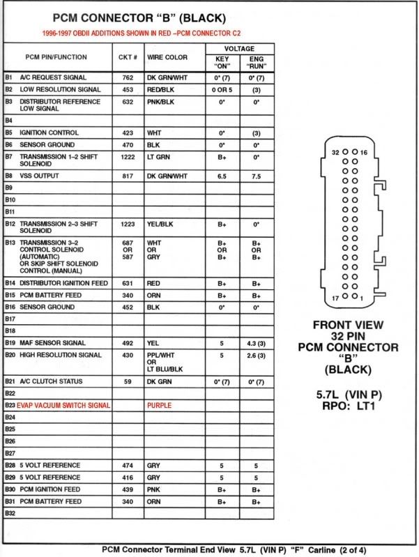
-Black connector with the VSS OUTPUT
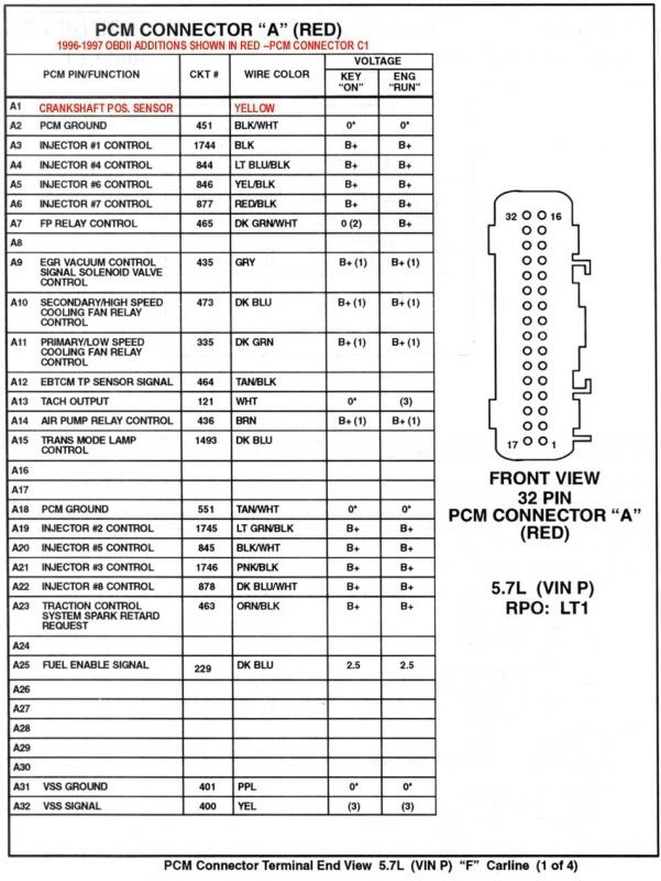
-Red connector with VSS GROUND and VSS SIGNAL
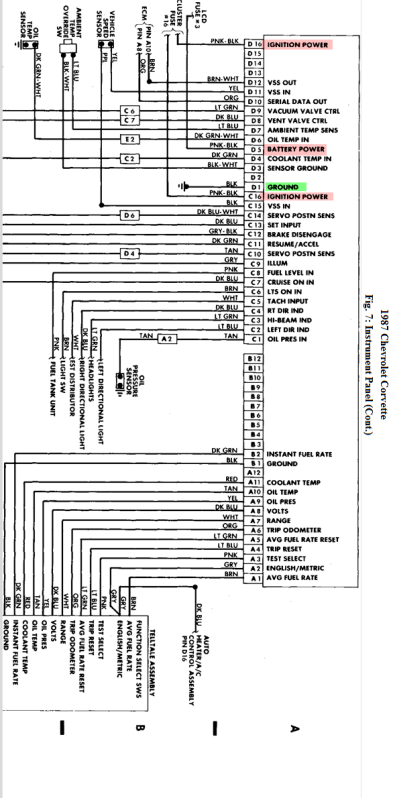
-87 dash with VSS IN (2 of them) and VSS OUT
Looks like two different ways they ran VSS for these years.
What could I connect here to make this work?
I need to hook up the 87 dash up to the 95 pcm for the signal.
Everything else works but the odometer and speedometer.
BTW engine and Trans are 95
LT1 wiring had set up the VSS OUTPUT to be hooked up to the dash.
I've tried all the VSS ports from my dash and it doesn't work.
Diagrams listed below:
-Black connector with the VSS OUTPUT
-Red connector with VSS GROUND and VSS SIGNAL
-87 dash with VSS IN (2 of them) and VSS OUT
Looks like two different ways they ran VSS for these years.
What could I connect here to make this work?

Melting Slicks


Joined: Aug 1999
Posts: 2,240
Likes: 42
From: Baltimore, MD USA
The Digital Dash Cluster Speedometer would need the same wiring as
it originally had.
The VSS in your original transmission put out a sine wave of 4k pulse per mile.
I'm not sure what your new transmission VSS puts out. (4l60E).
Yellow wire from the VSS to pin D11 of the Digital Cluster.
Purple wire from the VSS to pin C15 of the Digital Cluster.
These same wires would also need to go to the 95 PCM.
Yellow wire from the VSS to pin A32 of the PCM.
Purple wire from the VSS to pin A31 of the PCM.
Also the PCM pin out diagram you posted is for a F body. (Camaro)
Is your PCM from a F body?. The Corvette is Y body.
There are some pin out differences but they don't appear they would
affect your swap.
Last edited by Hooked on Vettes; May 14, 2012 at 02:18 AM.

Safety Car


Joined: Jan 2004
Posts: 3,556
Likes: 13
On later cars , the speedo signal is a single wire from the CCM which received it's speed signal from the ECM /PCM
which is connected direct to the 4000 pulse VSS in trans.
Last edited by vetteoz; May 14, 2012 at 03:12 AM.
Race Director

Joined: Apr 2002
Posts: 10,036
Likes: 346
From: Anaheim CA
The '87 had the signal come from the VSS sender to the dash (VSS IN, pin D11 in your diagram) and then it went to the ECM (VSS OUT, pin D12 in the diagram). In later years they switched the path: through the PCM first and then to the dash.
It looks like you need to connect the VSS sender to PCM pin A32 VSS SIGNAL and connect PCM pin B8 VSS OUTPUT, to your dash VSS IN on pin D11. It looks like you might need to connect PCM pin A31 to the VSS sender also.
I have a vague recollection that the VSS senders changed in later years and they put out twice as many pulses per mile, so it's possible you might need to change the VSS sender. Hook everything up and if the dash says you're going half as fast as it should then you'll have to upgrade the VSS sender.
It appears that other folks were typing at the same time that I was. The above two posts weren't there when I started...
Last edited by Cliff Harris; May 14, 2012 at 03:28 AM.
Safety Car
Joined: Jan 2004
Posts: 3,556
Likes: 13
Melting Slicks
Joined: Aug 1999
Posts: 2,240
Likes: 42
From: Baltimore, MD USA
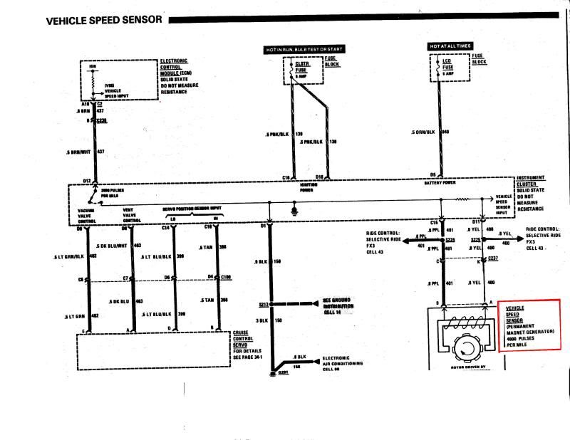
If 85-89 used a 2k pulse per mile VSS, there must be a typo
in the 89 service manual.
It shows a block diagram lower right corner that the VSS is 4k pulses
per mile.
If he needs to correct the VSS frequency so it can be
used on the 87 Dash Cluster he can use an electronic ratio
adapter.
If the wires are connected, I would think he would get some kind of reading on the display even if the frequency was off.
Something similar to the Dakota Digital's SGI-5 may work.
The SGI-5 can convert a sine wave from 4K to 2K but the converted
output signal does not appear from their description to be a sine wave.
You would need to contact them to see if it would work.
http://www.dakotadigital.com/index.c...rod/prd126.htm
Last edited by Hooked on Vettes; May 14, 2012 at 01:30 PM.
Thread Starter
Racer
Joined: May 2009
Posts: 256
Likes: 0
The Digital Dash Cluster Speedometer would need the same wiring as
it originally had.
The VSS in your original transmission put out a sine wave of 4k pulse per mile.
I'm not sure what your new transmission VSS puts out. (4l60E).
Yellow wire from the VSS to pin D11 of the Digital Cluster.
Purple wire from the VSS to pin C15 of the Digital Cluster.
These same wires would also need to go to the 95 PCM.
Yellow wire from the VSS to pin A32 of the PCM.
Purple wire from the VSS to pin A31 of the PCM.
Also the PCM pin out diagram you posted is for a F body. (Camaro)
Is your PCM from a F body?. The Corvette is Y body.
There are some pin out differences but they don't appear they would
affect your swap.
it originally had.
The VSS in your original transmission put out a sine wave of 4k pulse per mile.
I'm not sure what your new transmission VSS puts out. (4l60E).
Yellow wire from the VSS to pin D11 of the Digital Cluster.
Purple wire from the VSS to pin C15 of the Digital Cluster.
These same wires would also need to go to the 95 PCM.
Yellow wire from the VSS to pin A32 of the PCM.
Purple wire from the VSS to pin A31 of the PCM.
Also the PCM pin out diagram you posted is for a F body. (Camaro)
Is your PCM from a F body?. The Corvette is Y body.
There are some pin out differences but they don't appear they would
affect your swap.
The wires you mentioned, I hook those up acorrding to color? And would i Bridge the wires off the PCM into the dash? Would that be ok?
The '87 had the signal come from the VSS sender to the dash (VSS IN, pin D11 in your diagram) and then it went to the ECM (VSS OUT, pin D12 in the diagram). In later years they switched the path: through the PCM first and then to the dash.
It looks like you need to connect the VSS sender to PCM pin A32 VSS SIGNAL and connect PCM pin B8 VSS OUTPUT, to your dash VSS IN on pin D11. It looks like you might need to connect PCM pin A31 to the VSS sender also.
I have a vague recollection that the VSS senders changed in later years and they put out twice as many pulses per mile, so it's possible you might need to change the VSS sender. Hook everything up and if the dash says you're going half as fast as it should then you'll have to upgrade the VSS sender.
It appears that other folks were typing at the same time that I was. The above two posts weren't there when I started...
It looks like you need to connect the VSS sender to PCM pin A32 VSS SIGNAL and connect PCM pin B8 VSS OUTPUT, to your dash VSS IN on pin D11. It looks like you might need to connect PCM pin A31 to the VSS sender also.
I have a vague recollection that the VSS senders changed in later years and they put out twice as many pulses per mile, so it's possible you might need to change the VSS sender. Hook everything up and if the dash says you're going half as fast as it should then you'll have to upgrade the VSS sender.
It appears that other folks were typing at the same time that I was. The above two posts weren't there when I started...
Melting Slicks
Joined: Aug 1999
Posts: 2,240
Likes: 42
From: Baltimore, MD USA
Here's some information that may help.
Corvette Central has an article where a LS2
was installed in a 85. They used a 4l60E that
had a 4 pulse VSS. (Yes I understand you are
using a ZF6).
The ZF6 was first used in 89.
According to the ZF docs web-site
http://www.zfdoc.com/techinfo.htm
the ZF6 used a 4 pulse VSS. This would explain
why the 89 schematic I posted shows a 4 pulse
VSS.
This would indicated a 89 dash cluster speedometer
uses a 4 pulse signal from the VSS.
84-88 Dash cluster probably use a 2 pulse VSS.
The Corvette Central article says they used a
Dakota Digital SGI-5C to calibrate the speedometer
on the 85 dash cluster.
So it appears you can use the SGI-5C to convert
the 4 pulse VSS to a 2 pulse signal.
http://tech.corvettecentral.com/2010...-c4-corvettes/
Last edited by Hooked on Vettes; May 14, 2012 at 05:31 PM.
Corvette Stories
The Best of Corvette for Corvette Enthusiasts

Top 10 Most Explosive Corvettes Ever Made: Power-to-Weight Ratio Ranked!
Joe Kucinski
150 hp to 1,250 hp: Every Corvette Generation Compared by the Specs That Matter
Joe Kucinski
8 Coolest Corvette Pace Cars (and Replicas) of All Time
Verdad Gallardo
Top 10 Corvette Engines RANKED by Peak Torque (70+ Years of Muscle!)
Joe Kucinski
Corvette ZR1X Will Be Pacing the Indy 500, And Could Probably Race, Too!
Verdad Gallardo
Top 10 Corvettes Coming to Mecum Indy 2026!
Brett Foote
Top 10 C9 Corvette MUST-HAVES to Fix These C8 Generation Flaws!
Michael S. Palmer
10 Revolutionary 'Corvette Firsts' Most People Don't Know
Joe Kucinski
5 Reasons to Upgrade to an LS6-Powered Corvette; 5 Reasons to Stay LT2
Michael S. Palmer
Thread Starter
Racer
Joined: May 2009
Posts: 256
Likes: 0
Here's some information that may help.
Corvette Central has an article where a LS2
was installed in a 85. They used a 4l60E that
had a 4 pulse VSS. (Yes I understand you are
using a ZF6).
The ZF6 was first used in 89.
According to the ZF docs web-site
http://www.zfdoc.com/techinfo.htm
the ZF6 used a 4 pulse VSS. This would explain
why the 89 schematic I posted shows a 4 pulse
VSS.
This would indicated a 89 dash cluster speedometer
uses a 4 pulse signal from the VSS.
84-88 Dash cluster probably use a 2 pulse VSS.
The Corvette Central article says they used a
Dakota Digital SGI-5C to calibrate the speedometer
on the 85 dash cluster.
So it appears you can use the SGI-5C to convert
the 4 pulse VSS to a 2 pulse signal.
http://tech.corvettecentral.com/2010...-c4-corvettes/
Corvette Central has an article where a LS2
was installed in a 85. They used a 4l60E that
had a 4 pulse VSS. (Yes I understand you are
using a ZF6).
The ZF6 was first used in 89.
According to the ZF docs web-site
http://www.zfdoc.com/techinfo.htm
the ZF6 used a 4 pulse VSS. This would explain
why the 89 schematic I posted shows a 4 pulse
VSS.
This would indicated a 89 dash cluster speedometer
uses a 4 pulse signal from the VSS.
84-88 Dash cluster probably use a 2 pulse VSS.
The Corvette Central article says they used a
Dakota Digital SGI-5C to calibrate the speedometer
on the 85 dash cluster.
So it appears you can use the SGI-5C to convert
the 4 pulse VSS to a 2 pulse signal.
http://tech.corvettecentral.com/2010...-c4-corvettes/
I see they have a tach converter too but Mines hooked up and it seems to be correct to me. Is the signal for that different too?
I remember being told back in the day before this project that its just all run off voltage
 .
.
Melting Slicks
Joined: Aug 1999
Posts: 2,240
Likes: 42
From: Baltimore, MD USA

Thread Starter
Racer
Joined: May 2009
Posts: 256
Likes: 0
I bought the SGI-5. This solves the PPM conversion and the Differential gear change I did.
Now how would this setup work? I believe the VSS from the ZF6 gets hooked up into the SGI-5. Then outputs from there to the PCM and DASH, or PCM first, then from PCM to DASH.
If I cut the VSS wires to go to the SGI-5, the PCM will not receive the signal and the ground vss. It will only receive a signal from the SGI-5, which should throw a code. But I need to set the correct speed before it hits the PCM because currently my Speedo gears are not setup for the 3.55 rear gears I have now. I could have the wrong fuel/air mixture as of right now.
Also the Dash needs two VSS inputs so I'm a little confused on how this will work.