Alternator good not charging battery
 08-20-2015, 09:44 PM
#1
Advanced

Thread Starter

Member Since: Mar 2015
Location: Winchester Bay Oregon
Posts: 80
Likes: 0
Received 0 Likes
on
0 Posts
last night my son (Judd) headed home ( a 20 mile drive) half way home his car died. i went to help him and the battery was dead. it was clicking and lights were very dim. it was dark so we called a wrecker. This morning i took the alternator off and had a very well known rebuilder test the alternator with a machine that even put a load on it. He said it was fine. Sent me home and told me to check the voltage at the back of the alternator at the large red wire. I had been charging the battery and it had a 12.86v across the positive to negative terminals when I got back and reinstalled the alternator. I then put the black probe of my multimeter on the negative battery post and the positive probe on the red wire at the alternator and it read the same. He told me to check the plug at at the plug on the alternator with a test light. It has a 4 wire plug but only 3 wires are there. The large wire on one end was red. He said that would have power all the time and would light up. The next wire was blue and in the second position. it was supposed to light up but did not. He said it was supposed to tell the voltage regulator when to tell the alternator to charge the battery. it was supposed to light up when the ignition switch was on or the engine running it did not and he said it is connected to a amp fuse in the fuse box. There were three 5 amp fuses and all could have been related to the alternator. I changed all 3 and it still did not light up at the plug at the alternator. The wires all pass thru a loom that sits between the heads and intake manifold in a plastic cover and exits the back near the firewall. it only shows 11.9v at the large red wire at the alternator and the volt meter on the dash gauge. so the alternator is capable of charging but will not charge the battery. is it a bad wire between the alternator and the fuse or could it be something else? It is not charging at all and the voltage dropped to 11.7 in a couple minutes of running.(this is an 89 tpi car)
Last edited by wolfer; 08-20-2015 at 10:03 PM.
 08-20-2015, 10:00 PM
#2

There's a fusible link that attaches to the fuse box on the fire wall. Open the wire harness and look for an orange wire that might be burned through. Its designed to melt before the wire harness does.
08-20-2015, 10:06 PM
#3
Advanced
Thread Starter
Member Since: Mar 2015
Location: Winchester Bay Oregon
Posts: 80
Likes: 0
Received 0 Likes
on
0 Posts
The fuse box is on the side of the dash touching the door panel. I am not sure where to look in the loom for the orange fusable link wire. (close to the pass side of the firewall or close to the alternator or battery?
08-20-2015, 11:28 PM
#4

Battery
08-20-2015, 11:47 PM
#5
Race Director


Most of the fusible links are behind the battery. If you measured battery voltage on the large red output wire on the alternator then the fusible link is OK.
The ignition switch applies a voltage to the field coils of the alternator when the engine is first started to "prime the pump". This voltage comes from a resistor in the dash that simulates the old GEN bulb idiot light. I'm away from home so I don't have access to my FSM to get more specific about what the various wires do. You should be able to find something with Google.
The ignition switch applies a voltage to the field coils of the alternator when the engine is first started to "prime the pump". This voltage comes from a resistor in the dash that simulates the old GEN bulb idiot light. I'm away from home so I don't have access to my FSM to get more specific about what the various wires do. You should be able to find something with Google.
08-21-2015, 12:55 AM
#6


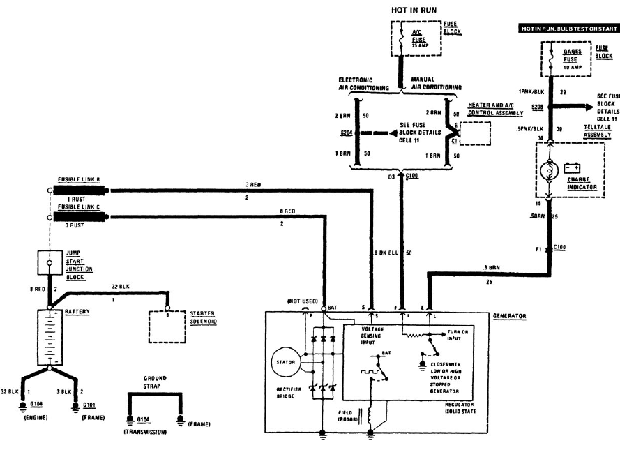
Here is a portion of the charging diagram that I believe is correct for an '89. It sounds as if you've got a very accommodating electrical shop so you might take this diagram and let him explain rather than us. The two fuses you need to check are the AC 25AMP, GAUGES 10AMP. The two fusible links are attached to the junction block behind the battery.
At a fast idle (with no accessories on) the voltage between the + post of battery and - post OR ground should be 13 - 16V.
If Cliff is still around he may comment. There's some preliminary tests that could be done with the alternator connector disconnected and key in the RUN position but after that it suggests a load charge and alternator check, you've done that (alternator test at shop) so I believe that may be unnecessary. Your '89 I believe should have a charge indicator in the DIC maybe. Is it lit? I've never owned an earlier MY.
You mentioned checking the BLUE correctly so the first check I believe would be the AC FUSE, then check the BLUE again with KEY in RUN and of course you need to check/confirm the GAUGES fuse.
Last edited by WVZR-1; 08-21-2015 at 05:57 AM.
 08-21-2015, 03:43 AM
#7
Melting Slicks


 08-21-2015, 04:32 PM
#9
Advanced
Thread Starter
Member Since: Mar 2015
Location: Winchester Bay Oregon
Posts: 80
Likes: 0
Received 0 Likes
on
0 Posts
The rebuilder told me the battery did not have a short or dead cell or it would have overworked the alternator and blew it up. i did change the gauges fuse it has a 5 amp in it and I put another one in it. I did not check the ac fuse I will have him look when he calls today.
08-21-2015, 04:46 PM
#10
The rebuilder told me the battery did not have a short or dead cell or it would have overworked the alternator and blew it up. i did change the gauges fuse it has a 5 amp in it and I put another one in it. I did not check the ac fuse I will have him look when he calls today.
08-21-2015, 08:20 PM
#11
Advanced
Thread Starter
Member Since: Mar 2015
Location: Winchester Bay Oregon
Posts: 80
Likes: 0
Received 0 Likes
on
0 Posts
Not sure about the 5 amp fuse in the gauge fuse holder but that is what was in it. I pulled it out and put a new 5 amp back in it. There were no 5 amp fuses blown. My son checked many fuses when he broke down but did not find any blown. he did not check all of them and probably has not checked the AC fuse yet.
08-21-2015, 11:02 PM
#12
Race Director
http://www.corvettepacifica.com/cate...rmation-center
My car has a resistor in the dash that simulates the GEN bulb.
08-22-2015, 12:59 AM
#14
Melting Slicks
I should note I could charge the old battery up, drive, then test and it would read lower voltage. New batt stays the same from full charged after a drive. I was debating if it was the underdrive pulley or alt and then decided to swap the batt from my c3 before I messed with anything else. Also my batt wasn't going down a lot but I was testing the volts with the new pulleys anyway.
08-22-2015, 04:13 AM
#15

You can use the dash , it should be around 14 when running and mabey dip to 13.8 that is the alternater output if it doesn't hold a charge the battery needs replaced or distilled water added. They do drie out I have filled mine 2x already to the bottom of the plastic . Good luck
08-22-2015, 04:22 AM
#16
I didn't know they put that in there. My car does not have it. According to this link that started in 1988:
http://www.corvettepacifica.com/cate...rmation-center
My car has a resistor in the dash that simulates the GEN bulb.
http://www.corvettepacifica.com/cate...rmation-center
My car has a resistor in the dash that simulates the GEN bulb.
'84 & '85 reference I believe just a 10 OHM "resistance wire" and the '86 references the 510 OHM resistor so apparently there were changes.
Resistors - I hate resistors. Yesterday I had to drive 45 miles to put my hands on correct combinations for a VATS key by-pass for a '95 Park Avenue. The most aggravating part was it was a 15 (11800 OHM) so I had to go through a literal pile of blister packs because the simple packs on the display (that would have worked) were sold out. I ended up with a 3 in a series for the build.
I wasn't doing the job and when I laid out the combination for the fellow at the shop he looked at me with a somewhat bewildered look and I don't know that he understood the math either. I gave him the resistors, a 4 ft length of 3/32 heat shrink, a small purchase of solder, drew the 3 in a series and explained where to cut the wires.
The electronics shop was a good find though but the fellow working was aggravated as he!! because he couldn't get his computer system to boot, quite an electrical storm the night before and here's a guy that drove 45 miles wanting resistors. There must have been 10,000 + resistors in the back room with most all of the 1/4 & 1/2 WATT scattered, the 1 & 2 WATT looked to be better organized.
The '95 Park Avenue key cylinder wires are in a 48 pin component that's bolted together under the dash with a rather unusual secondary latching device. I couldn't use my VATS Interrogator to easily confirm crank but it certainly acted like a resistance issue.
Got a phone call at home 90 minutes later that the car was "on the street".