twin turbo lt5 camero engine pics
 07-12-2010, 12:53 AM
#1
Advanced

Thread Starter
Member Since: Aug 2009
Location: Albuquerque NM
Posts: 55
Likes: 0
Received 0 Likes
on
0 Posts
I decided to start a new thread just on the engine. After this engine is all done If there is a demand for it I am going to write a small article on what I have learned about this engine its good points, bad points, and things to watch out for . I thank all the good people that gave me info on this engine as I was putting it together. You all will be mentioned When I write this article on the LT5 thanks everyone enjoy the pics
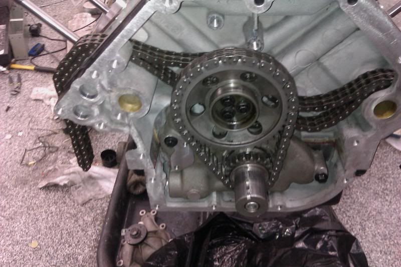
Here is the primary chains
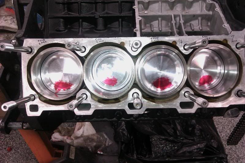
Here is the left side the red dykem is so I know where the bottom of the piston is just a helping hand
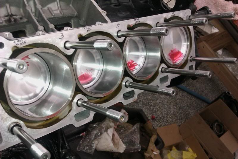
This is the right side notice the head studs Top of the line ARP 2000
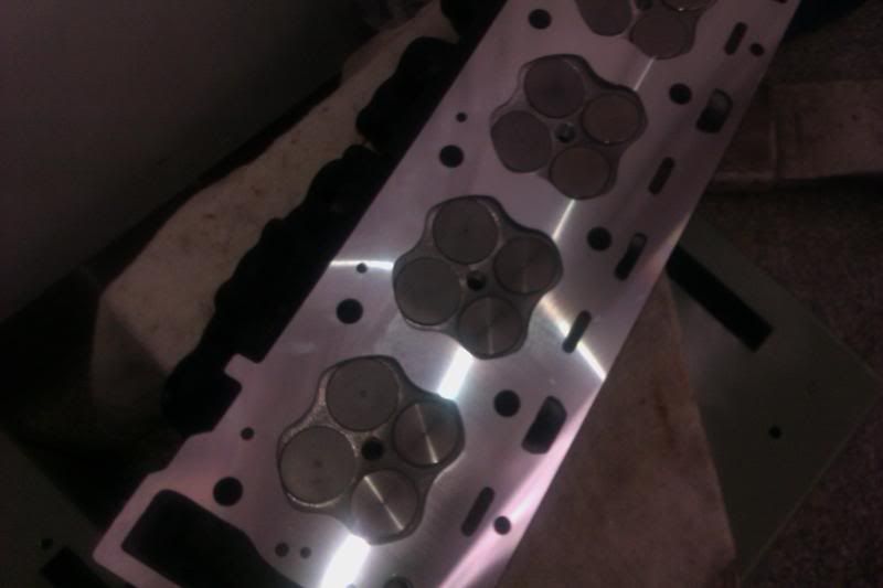
The head after new valves and surfaced
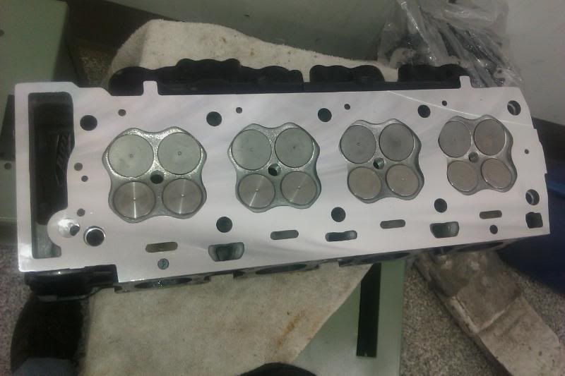
The other head
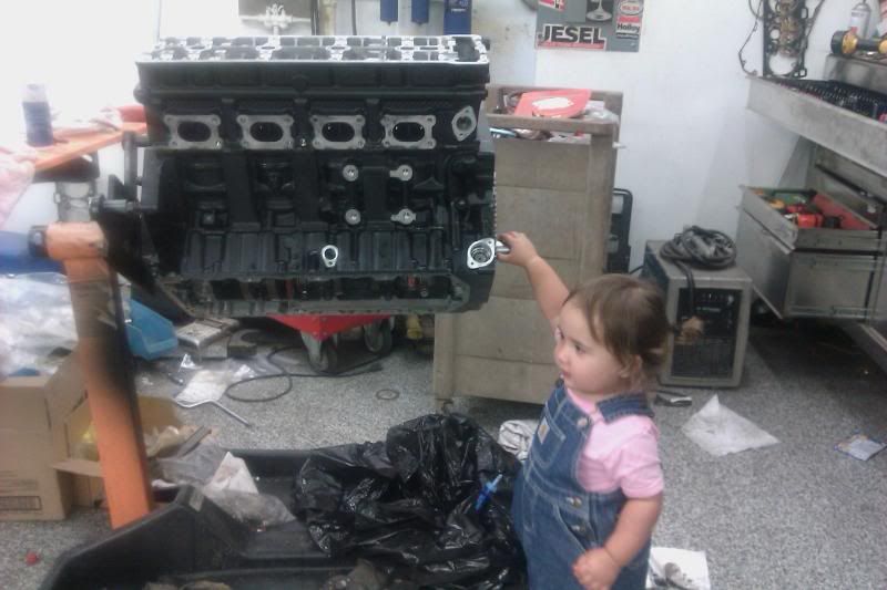
My baby at 18 months helping dad put her first LT5 together she is turning the crank
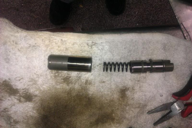
After taking the timming chain tentioners apart to reseat them before installation
Close up view of the tentioner snap ring that has to be compressed to assemble it
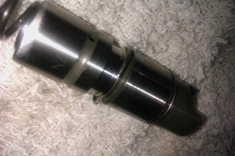
Another view of the snap ring
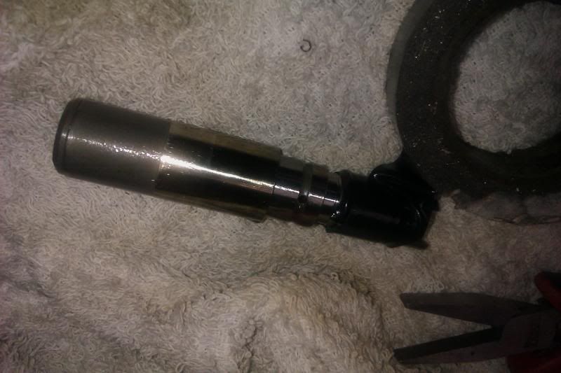
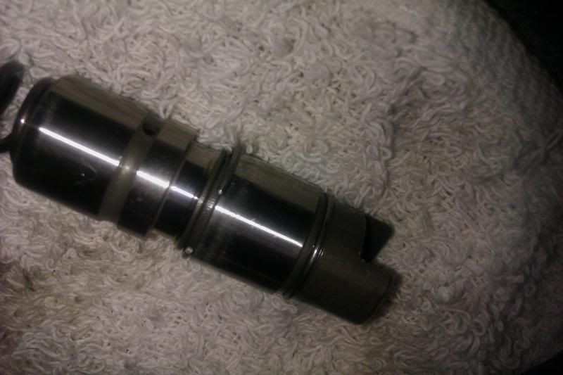
Using electrical tape to compress the snap ring so I can assemble the tentioner
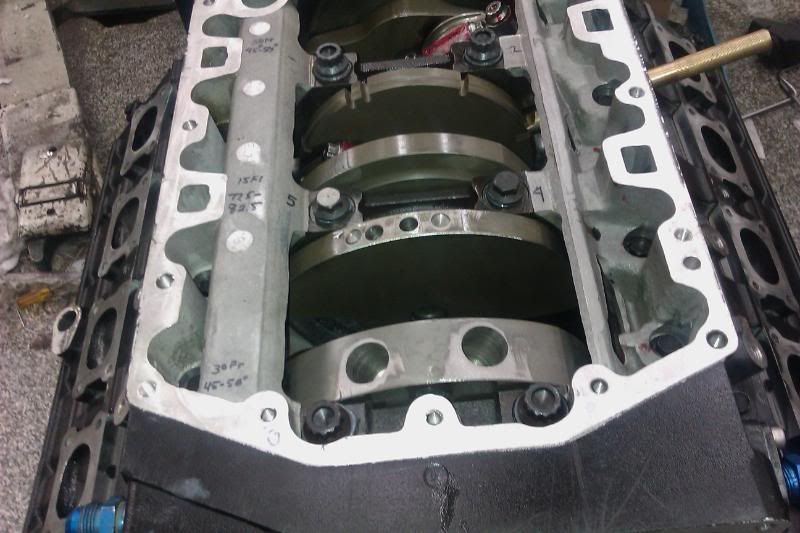
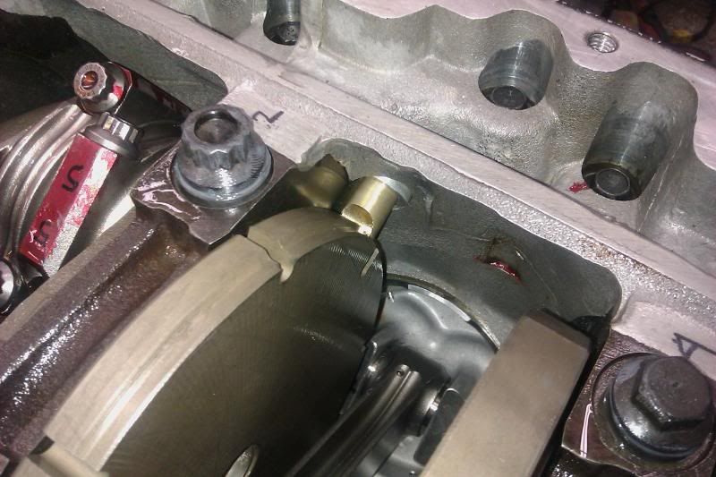
The bottom of the assembled engine from the front showing the ARP main bolts on 1 3 5 mains magic marker is so I know the torquing sequence and the amount to torque it to
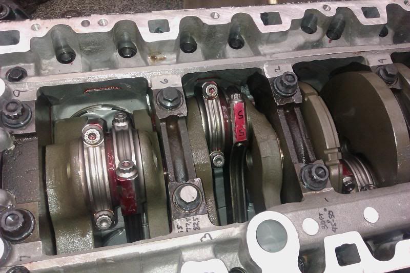
Side view of the bottom end look at those nice aftermarket rods again the red is so I can read what rod is where
Close up of the tool I made to time the crank to the cams
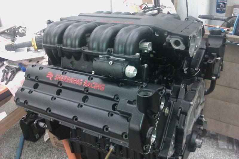
Picture 1 of the engine almost done still need to work on fuel spark and front drive stuff

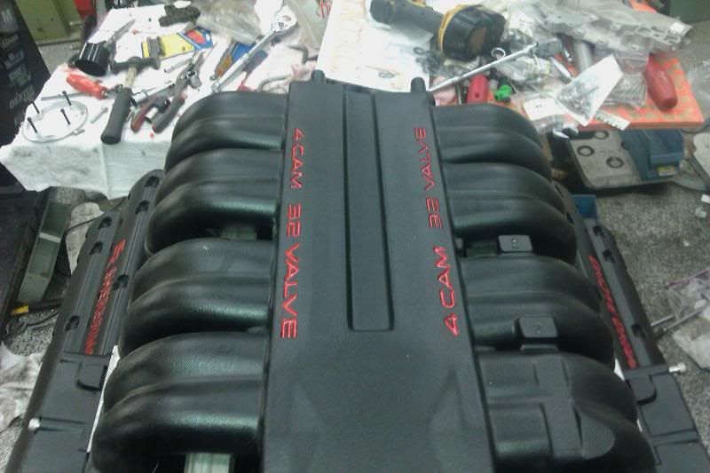
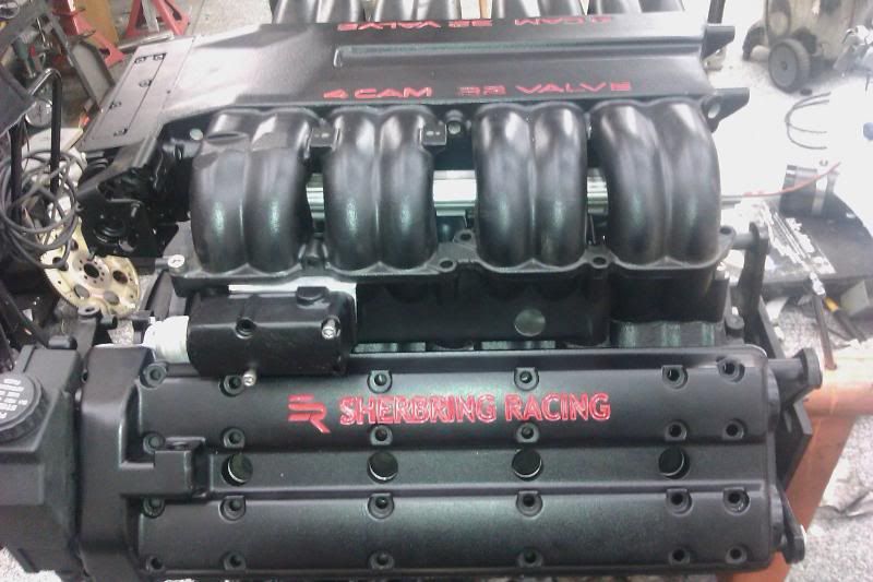
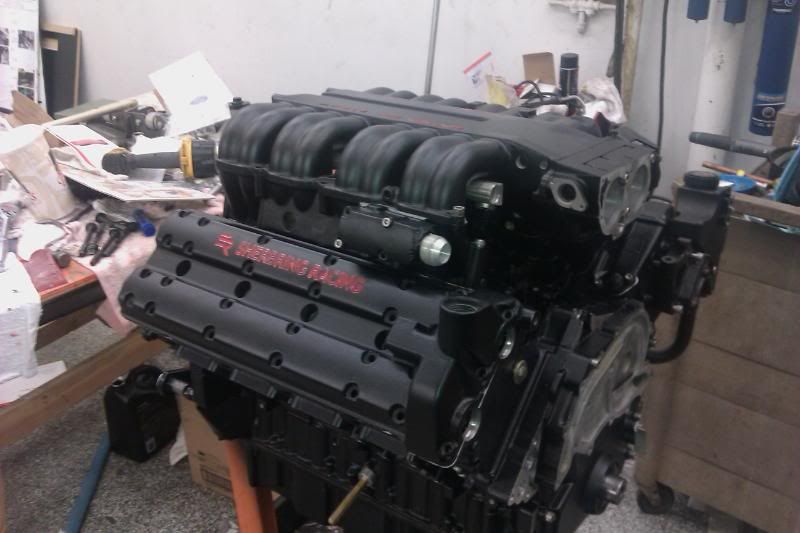
Another picture top view
Here is the primary chains
Here is the left side the red dykem is so I know where the bottom of the piston is just a helping hand
This is the right side notice the head studs Top of the line ARP 2000
The head after new valves and surfaced
The other head
My baby at 18 months helping dad put her first LT5 together she is turning the crank
After taking the timming chain tentioners apart to reseat them before installation
Close up view of the tentioner snap ring that has to be compressed to assemble it
Another view of the snap ring
Using electrical tape to compress the snap ring so I can assemble the tentioner
The bottom of the assembled engine from the front showing the ARP main bolts on 1 3 5 mains magic marker is so I know the torquing sequence and the amount to torque it to
Side view of the bottom end look at those nice aftermarket rods again the red is so I can read what rod is where
Close up of the tool I made to time the crank to the cams
Picture 1 of the engine almost done still need to work on fuel spark and front drive stuff
Another picture top view
Last edited by TopfuelDragracer; 07-12-2010 at 01:21 AM.


 07-13-2010, 12:12 AM
#6
Drifting

Member Since: Jun 2001
Location: Kennewick,WA., USA
Posts: 1,304
Likes: 0
Received 5 Likes
on
4 Posts

interesting main bolt combo. ARP must have had some off the shelve bolts for the larger size to fit?
What kind of stretch factor do they have compared to the stock bolts that were replaced.
What kind of stretch factor do they have compared to the stock bolts that were replaced.
07-13-2010, 07:58 AM
#7
Racer
Member Since: Sep 2009
Location: Sherbrooke Quebec
Posts: 408
Likes: 0
Received 0 Likes
on
0 Posts
I decided to start a new thread just on the engine. After this engine is all done If there is a demand for it I am going to write a small article on what I have learned about this engine its good points, bad points, and things to watch out for . I thank all the good people that gave me info on this engine as I was putting it together. You all will be mentioned When I write this article on the LT5 thanks everyone enjoy the pics
Here is the primary chains
Here is the left side the red dykem is so I know where the bottom of the piston is just a helping hand
This is the right side notice the head studs Top of the line ARP 2000
The head after new valves and surfaced
The other head
My baby at 18 months helping dad put her first LT5 together she is turning the crank
After taking the timming chain tentioners apart to reseat them before installation
Close up view of the tentioner snap ring that has to be compressed to assemble it
Another view of the snap ring
Using electrical tape to compress the snap ring so I can assemble the tentioner
The bottom of the assembled engine from the front showing the ARP main bolts on 1 3 5 mains magic marker is so I know the torquing sequence and the amount to torque it to
Side view of the bottom end look at those nice aftermarket rods again the red is so I can read what rod is where
Close up of the tool I made to time the crank to the cams
Picture 1 of the engine almost done still need to work on fuel spark and front drive stuff
Another picture top view
 07-14-2010, 12:56 AM
#8
Advanced
Thread Starter
Member Since: Aug 2009
Location: Albuquerque NM
Posts: 55
Likes: 0
Received 0 Likes
on
0 Posts
I engraved the valve covers on my mill and took a syringe with red paint and painted it not as perfect as I would like but close. Sherbring Racing is my racing company google it.
The rods are Egale SBC +.125 long with ARP2000 bolts and the pistons are low compression 4.000" bore Ross. The CID I think is now 366. I slightly overbalanced it when I balanced it and used the stock Crank.
As the main bolts go GM says that all fastners on the mains are torque to yield which means one use only. Everybody uses them more than once but my opinion is 2 times max. So the main bolts that are used on 1,3,5 mains are not avalible anymore so I contacted ARP main plant and talked to ther over stock guy and asked if in inventory they had any m12 x112mm bolts they had 8, m12 x109 a little short but think it will work . Wish it was 112 long like stock but new fasteners are better than 4 or 5 time used stretch to yeild fastners. So 200,000psi fastener torqued to 75% yield is 86 ftlbs it just so happens that 30 ftlbs and 85 dergee is 83 ftlbs so that is where I left them providing a preload of 15,540 lbs of force. I am hopefull that that is more than the stock bolts. I hope that answers your question
Now I am figuring out how to use coil on plug and elimanate the 4 ugly coils under the manifold. Makes it cleaner and gives me more room for fuel system