
Write-Up: Monster 2 Catch Can for Boosted Centri! (Pics)
 04-17-2013, 11:24 PM
#1
Team Owner


Thread Starter
First and foremost I am going to cover the rubber line with this Black Nylon Sleeving Mesh from "Grainger", made specifically for tubes like this: This is the size and part number for our -8 AN (1/2" inner Dia.)
https://www.grainger.com/Grainger/ww...peaheadSearch=
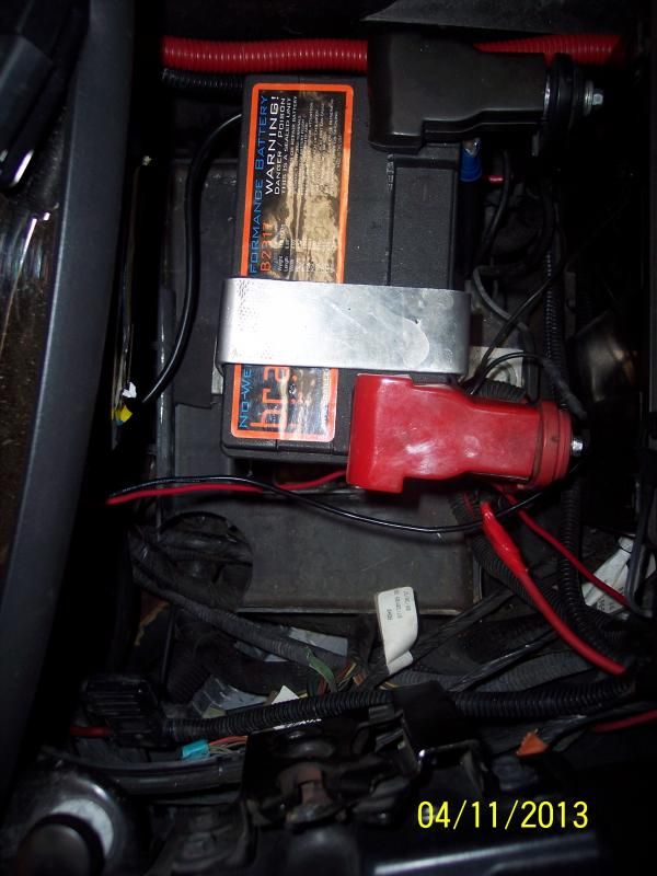
Secondly here is my write-up on the Braille battery install and yes we have "R" Right side positive terminal -
http://forums.corvetteforum.com/c5-t...ll-w-pics.html
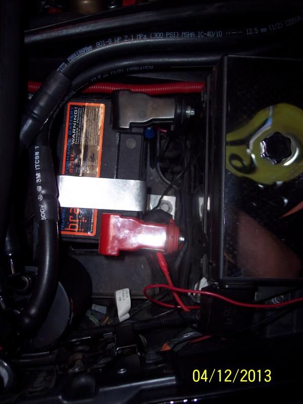
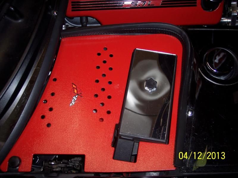
Battery Den and Battery Tray Trimmed -
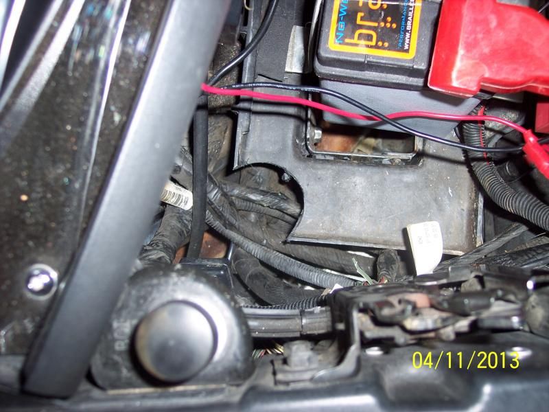
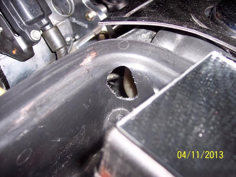
Holes drilled towards front for the tubing to go to the Manifold Neck and Supercharger -
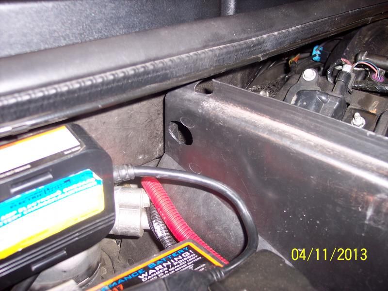
One Hole toward the fire wall going to the Drivers side Valve Cover from Center of Catch Can -
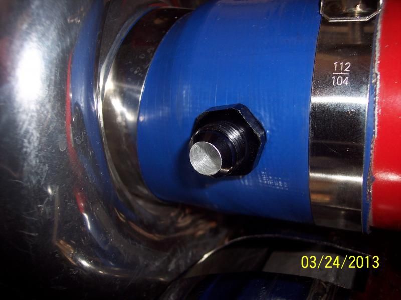
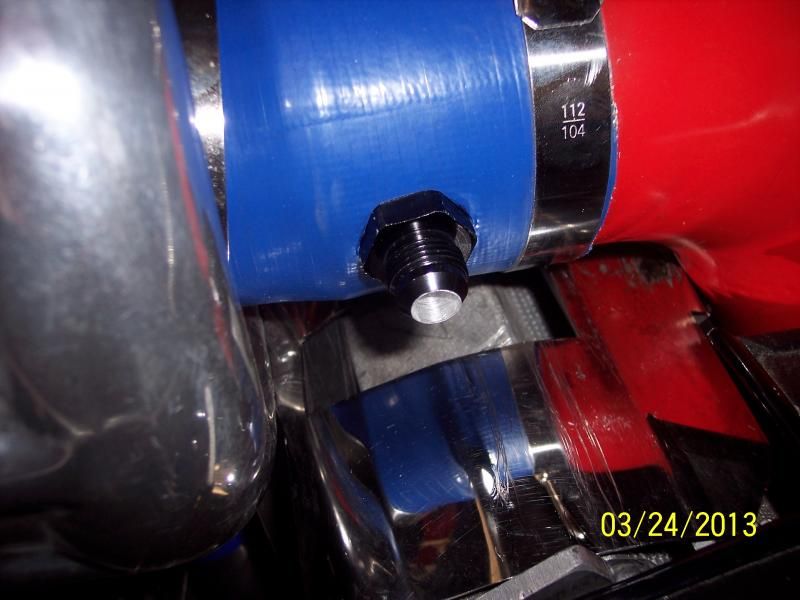
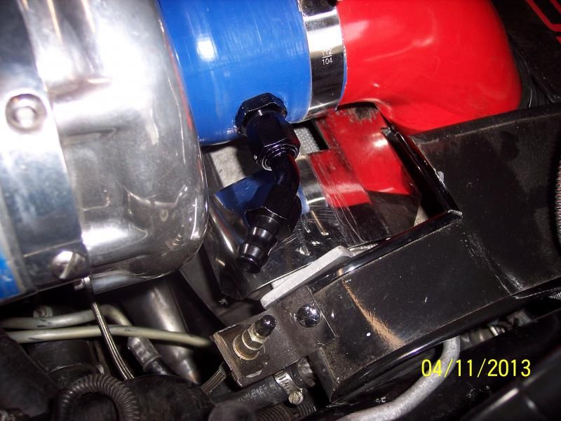
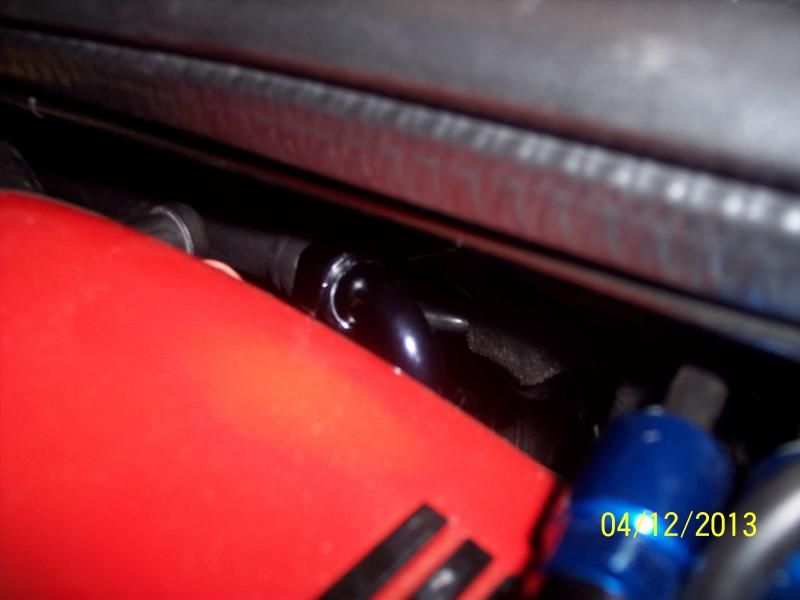
Supercharger -8 AN Bulkhead fitting hogged out a little extra for best volume and the -8 AN 45* Barbed Hose fitting to go to the Catch Can
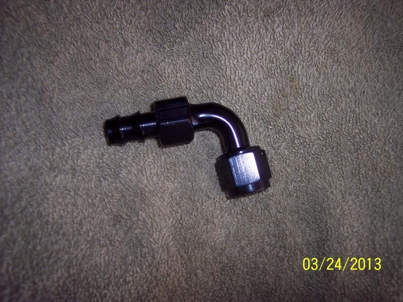
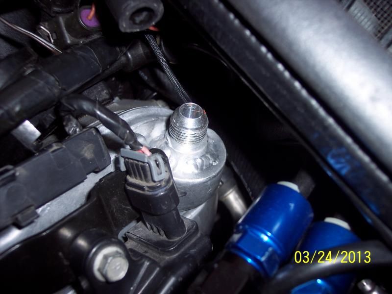
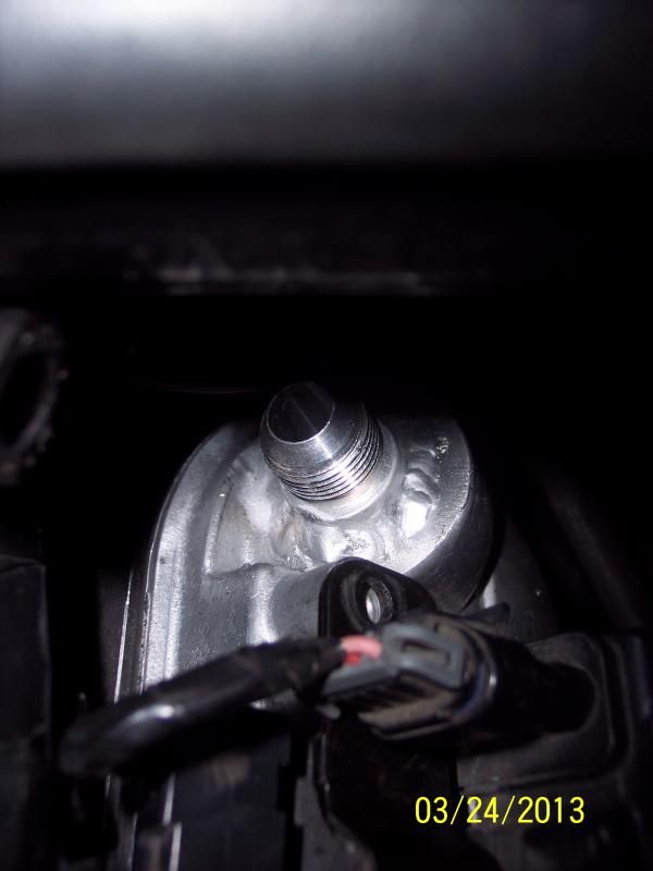
Valve Cover -8 AN fitting welded on and the 90* Barbed hose fitting to go to the back side of Catch Can
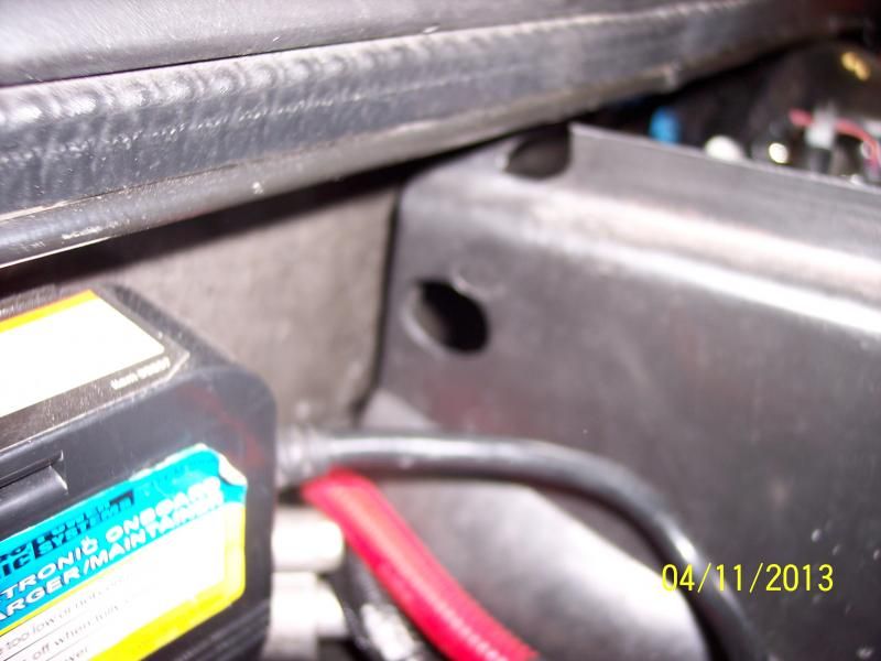
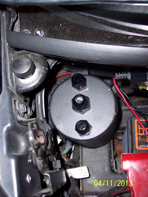
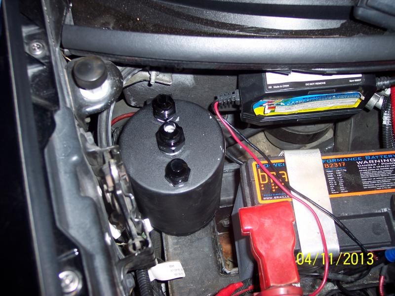
Catch Can Location and Height
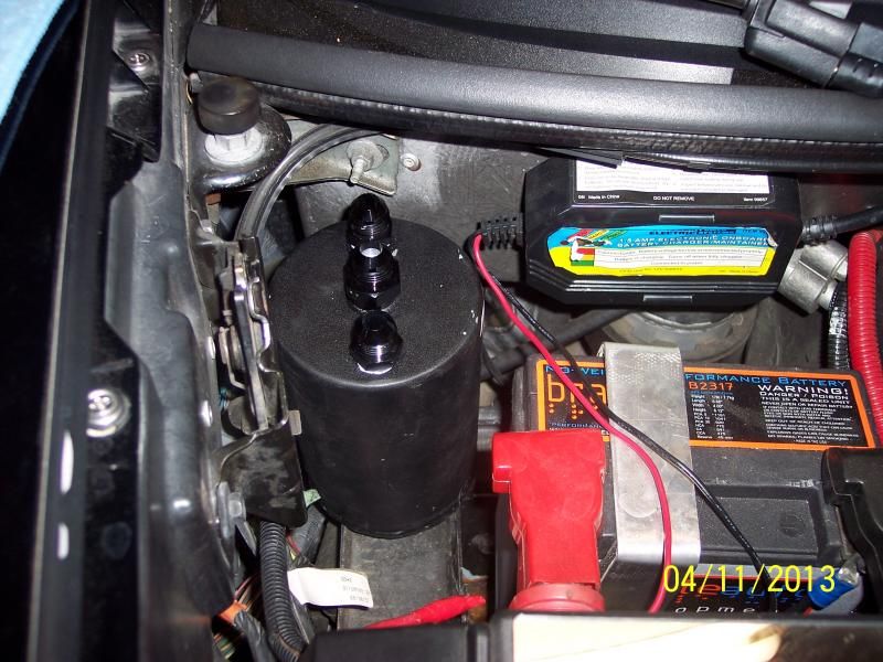
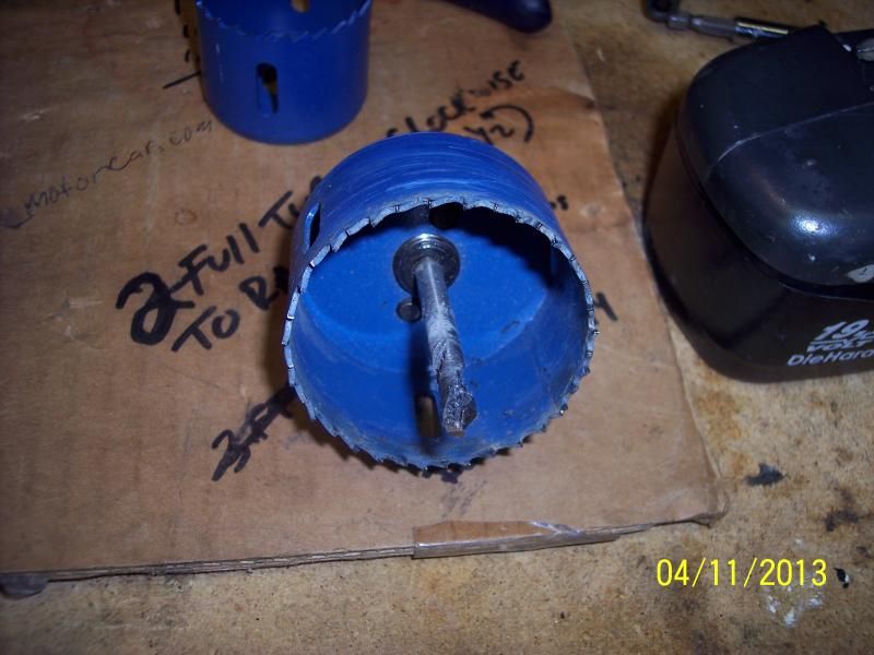
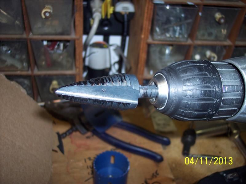
Tools I used 2 1/2" hole saw to cut of corner of battery tray and Uni-bit to make front Double/Stacked Hole and Rear/Firewall hole in the battery den wall
I hope this helps and as I said I will make a full write-up with these and more pictures, including the tubes being ran and routed correctly!
I will be able to retain my coil covers and everything else with little intrusion to the engine bay!
I am hoping, if all works out fine, to take it to work and take a couple of hours off and go over to finish the Dyno tuning on it - that should be sufficient enough to pull it and check it -
I did dot run a tube down for now - that might come later - I can "EASILY" unhook the C/C and lift it out and do it on the bench as opposed to getting under the Vette to drain it out.
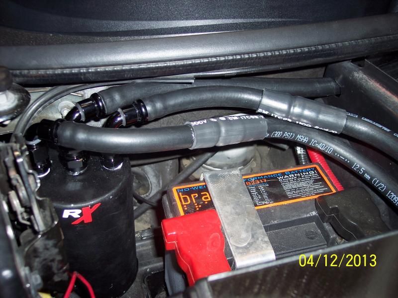
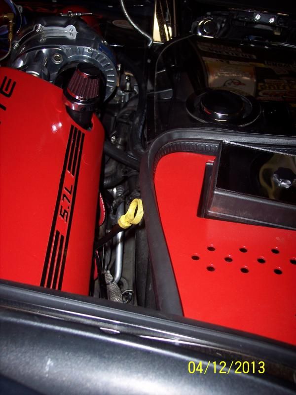
Here are a few more pics of the finished up install:
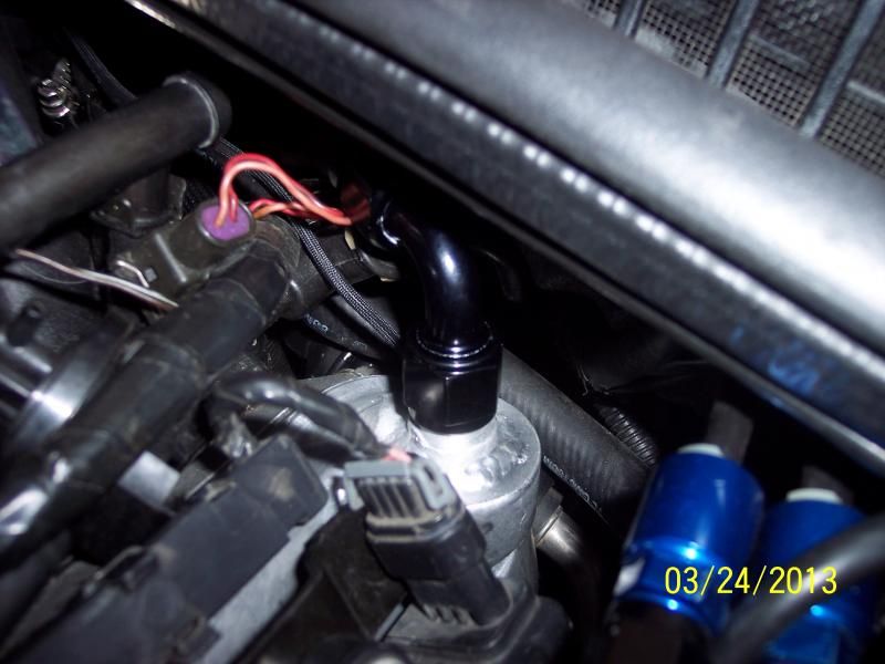
To the Drivers Valve Cover:
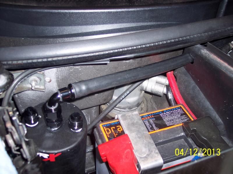
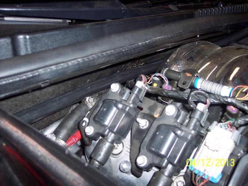
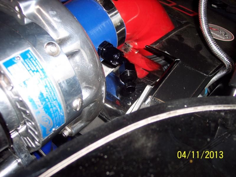
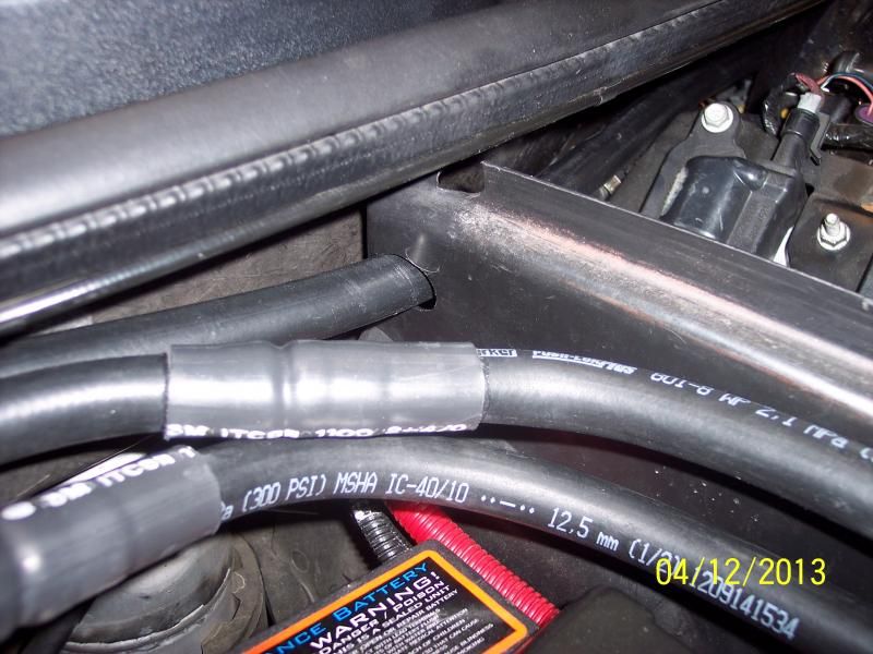
The other two hooked up, one to the Supercharger w/check-valve the other to the intake manifold w/check-valve
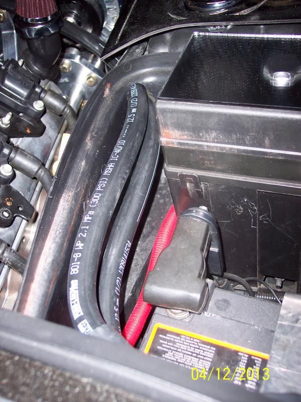
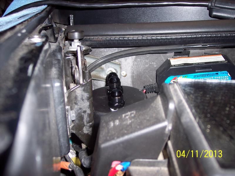
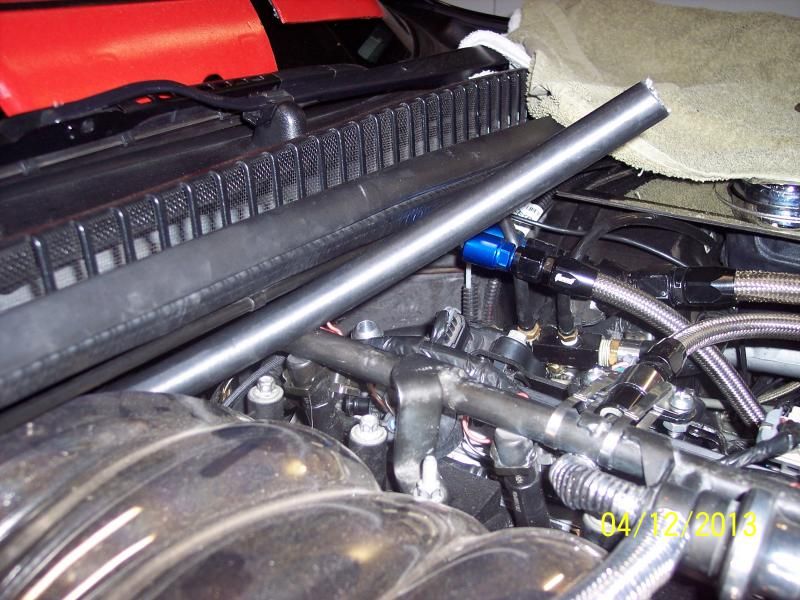
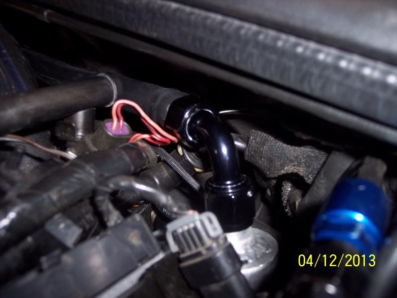
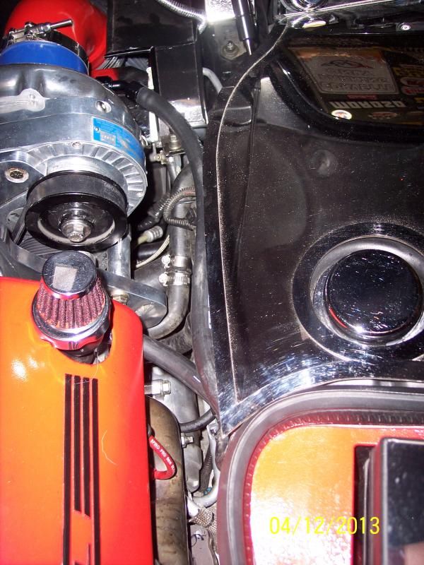
Supercharger Connection:
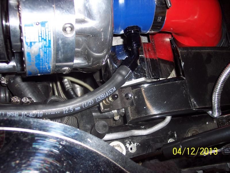
One going to Supercharger and the other Branching off to the manifold:
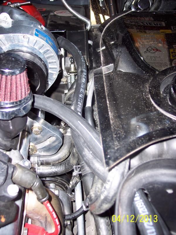
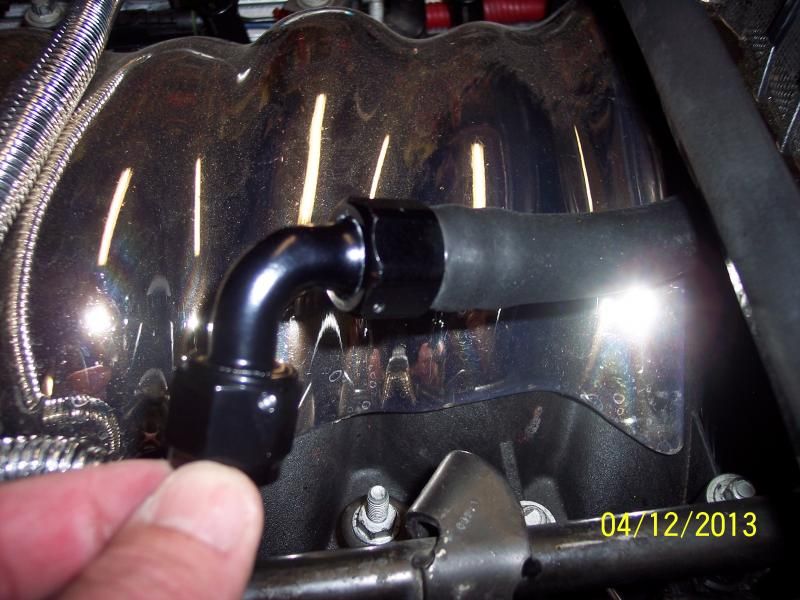
At the Manifold:
With all the Covers Back On:
Thanks,Matt
https://www.grainger.com/Grainger/ww...peaheadSearch=
Secondly here is my write-up on the Braille battery install and yes we have "R" Right side positive terminal -
http://forums.corvetteforum.com/c5-t...ll-w-pics.html
Battery Den and Battery Tray Trimmed -


Holes drilled towards front for the tubing to go to the Manifold Neck and Supercharger -

One Hole toward the fire wall going to the Drivers side Valve Cover from Center of Catch Can -


Supercharger -8 AN Bulkhead fitting hogged out a little extra for best volume and the -8 AN 45* Barbed Hose fitting to go to the Catch Can


Valve Cover -8 AN fitting welded on and the 90* Barbed hose fitting to go to the back side of Catch Can


Catch Can Location and Height


Tools I used 2 1/2" hole saw to cut of corner of battery tray and Uni-bit to make front Double/Stacked Hole and Rear/Firewall hole in the battery den wall


I hope this helps and as I said I will make a full write-up with these and more pictures, including the tubes being ran and routed correctly!
I will be able to retain my coil covers and everything else with little intrusion to the engine bay!
I am hoping, if all works out fine, to take it to work and take a couple of hours off and go over to finish the Dyno tuning on it - that should be sufficient enough to pull it and check it -
I did dot run a tube down for now - that might come later - I can "EASILY" unhook the C/C and lift it out and do it on the bench as opposed to getting under the Vette to drain it out.
Here are a few more pics of the finished up install:
To the Drivers Valve Cover:


The other two hooked up, one to the Supercharger w/check-valve the other to the intake manifold w/check-valve


Supercharger Connection:

One going to Supercharger and the other Branching off to the manifold:

At the Manifold:

With all the Covers Back On:


Thanks,Matt


 04-18-2013, 10:45 PM
#5
Team Owner

Member Since: Jan 2007
Location: cookeville tennessee
Posts: 28,846
Received 1,762 Likes
on
1,529 Posts

Matt, as always great write up and pic,s buddy.  Robert
Robert
 04-19-2013, 06:47 AM
#8
Team Owner
Thread Starter
 Very cool!
It should all work out, make sure you use a battery tender to keep it all charged up as it sits - yoou know how our Vette like to drain battery's
Thanks,Matt
11-02-2015, 09:47 AM
#10
Melting Slicks


First and foremost I am going to cover the rubber line with this Black Nylon Sleeving Mesh from "Grainger", made specifically for tubes like this: This is the size and part number for our -8 AN (1/2" inner Dia.)
https://www.grainger.com/Grainger/ww...peaheadSearch=
Secondly here is my write-up on the Braille battery install and yes we have "R" Right side positive terminal -
http://forums.corvetteforum.com/c5-t...ll-w-pics.html
Battery Den and Battery Tray Trimmed -
Holes drilled towards front for the tubing to go to the Manifold Neck and Supercharger -
One Hole toward the fire wall going to the Drivers side Valve Cover from Center of Catch Can -
Supercharger -8 AN Bulkhead fitting hogged out a little extra for best volume and the -8 AN 45* Barbed Hose fitting to go to the Catch Can
Valve Cover -8 AN fitting welded on and the 90* Barbed hose fitting to go to the back side of Catch Can
Catch Can Location and Height
Tools I used 2 1/2" hole saw to cut of corner of battery tray and Uni-bit to make front Double/Stacked Hole and Rear/Firewall hole in the battery den wall
I hope this helps and as I said I will make a full write-up with these and more pictures, including the tubes being ran and routed correctly!
I will be able to retain my coil covers and everything else with little intrusion to the engine bay!
I am hoping, if all works out fine, to take it to work and take a couple of hours off and go over to finish the Dyno tuning on it - that should be sufficient enough to pull it and check it -
I did dot run a tube down for now - that might come later - I can "EASILY" unhook the C/C and lift it out and do it on the bench as opposed to getting under the Vette to drain it out.
Here are a few more pics of the finished up install:
To the Drivers Valve Cover:
The other two hooked up, one to the Supercharger w/check-valve the other to the intake manifold w/check-valve
Supercharger Connection:
One going to Supercharger and the other Branching off to the manifold:
At the Manifold:
With all the Covers Back On:
Thanks,Matt
I would swap out the breather from the billet aluminum cleanside 1LE style separator though here:
http://www.coloradospeed.com/oil-pum...184ncqi4ohpbh1
That will better address the cleanside than the breather. You will plumb that into the end of your cone air filter for filtered fresh air and it prevents vapors or any momentary pressure when the checkvalves are switching.
For all that like this setup, the Coloradospeed "Monster" is similar in size and routing, but uses a billet clamp for the mount so easier to install like this example. The Elite E2-X Ultra is also a smooth side unit and can mount similar to these.


 11-02-2015, 05:17 PM
#12
Melting Slicks
And he understands it all as well. That is rare today. Good job Matt!
11-02-2015, 09:36 PM
#13
Team Owner
Thread Starter
Nice install Matt! It appears you have the correct checkvalves inside the shrink tube as long as both flow away from the can. One of the best installs I have seen. Nice work.
I would swap out the breather from the billet aluminum cleanside 1LE style separator though here:
http://www.coloradospeed.com/oil-pum...184ncqi4ohpbh1
That will better address the cleanside than the breather. You will plumb that into the end of your cone air filter for filtered fresh air and it prevents vapors or any momentary pressure when the checkvalves are switching.
For all that like this setup, the Coloradospeed "Monster" is similar in size and routing, but uses a billet clamp for the mount so easier to install like this example. The Elite E2-X Ultra is also a smooth side unit and can mount similar to these.
Is it only getting the clean air through the (what looks to be) 3/8" nipple that will go into the air filter?
Is that correct? or can one be had to match the rest of the system with a 1/2" Inlet?
Could you break down how the 1le cap breather works and the size nipple it has etc.? Really for me, any extra information on the cap before I make a decision will be extremely helpful and go a long way.
It just doesn't seem to be enough size for a clean source, but I could be wrong. So if you can please break it down for me on the cap.
I had a hard time with the underside of the cap picture on the website.
Oh, and does the cap drain any excess oil back into the valve cover too? Is it designed like that?
Thanks,Matt
11-03-2015, 11:42 AM
#14
Melting Slicks
Okay, my question then is this on the 1le breather:
Is it only getting the clean air through the (what looks to be) 3/8" nipple that will go into the air filter?
Is that correct? or can one be had to match the rest of the system with a 1/2" Inlet?
Could you break down how the 1le cap breather works and the size nipple it has etc.? Really for me, any extra information on the cap before I make a decision will be extremely helpful and go a long way.
It just doesn't seem to be enough size for a clean source, but I could be wrong. So if you can please break it down for me on the cap.
I had a hard time with the underside of the cap picture on the website.
Oh, and does the cap drain any excess oil back into the valve cover too? Is it designed like that?
Thanks,Matt
It can be custom ordered with any size up to -8 AN if desired for extra$, but your choice of 3/8" or 1/2" when you order is no extra.
The cleanside unit does drain back into the valve cover as it is only trapping oil when flow in is at the greatest. It only needs to trap it during the brief intervals the main separator's valves are switching to ensure proper evacuation at all times.
It can be ordered with the standard GM fit or with a "push in" style.
Hope that helps!
11-04-2015, 09:03 AM
#15
Team Owner
Thread Starter
It can be custom ordered with any size up to -8 AN if desired for extra$, but your choice of 3/8" or 1/2" when you order is no extra.
The cleanside unit does drain back into the valve cover as it is only trapping oil when flow in is at the greatest. It only needs to trap it during the brief intervals the main separator's valves are switching to ensure proper evacuation at all times.
It can be ordered with the standard GM fit or with a "push in" style.
Hope that helps!
I want to call today -
Who can I ask for and talk to about this? You?
Thanks,Matt
11-05-2015, 06:36 PM
#16
Melting Slicks
11-05-2015, 09:19 PM
#17
Team Owner
Thread Starter
I did not want to reduce anything from what the entire system is running (-8AN or 1/2") right now
Looking forward to seeing how it all works out - I do like and understand the concept, plus I do like the way it will drain any oil it may catch back into the valve cover - or as we call it "Mist" that the FRC's catch at times

Thanks,Matt
11-12-2015, 09:58 AM
#18
Melting Slicks
My error on the -8 AN fitting. Let us know how it works for you!
 03-14-2016, 07:40 PM
#20
Team Owner
Thread Starter
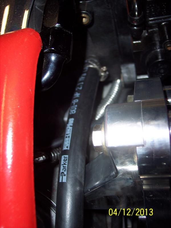
The outside Nut is part pf the Bulkhead itself -
Thanks,Matt
Last edited by madmatt9471; 03-14-2016 at 07:45 PM. Reason: Corrected