
Whats wrong with this catch can install?
 02-07-2014, 11:35 AM
#1
Pro

Thread Starter

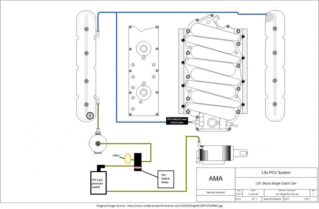
2000 C5 stock LS1 with STS kit. This is how the catch can was installed, which I think is incorrect and perhaps causing my dip stick to pop out at full boost. The dip stick blew out first time at full boost after having the can installed, but I haven't tried again since.
Here's a diagram of how it was installed:
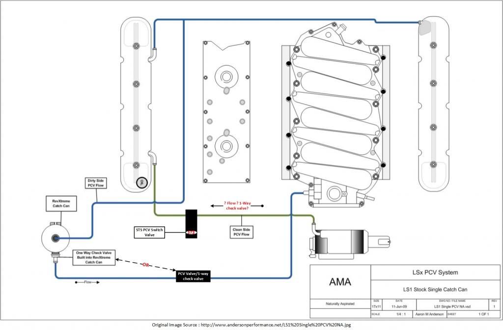
Here's how I was thinking it should be installed, but looking for feedback:
Thanks
Here's a diagram of how it was installed:

Here's how I was thinking it should be installed, but looking for feedback:

Thanks
 02-07-2014, 11:55 AM
#2
Le Mans Master


It looks to me that in either diagram once you're in boost the crankcase pressure has no where to go. If you're stuck on using a closed/catch can system you need the other RX can that has three nipples.
02-07-2014, 12:17 PM
#3
Pro
Thread Starter
Basically, the second diagram is the typical STS installation but with the catch can on the dirty side of the PCV (instead of the clean side the way it was installed).
If using a single catch can, why would someone install it on the fresh air source vs. the dirty side where the stock pcv valve is?
 02-07-2014, 02:29 PM
#5
Pro
Thread Starter
02-07-2014, 02:57 PM
#6
Melting Slicks


Is the catch can vented? (Breather on top) I have The Mighty Mouse boost can and mine has a breather
I will be setting it up like this
https://lh3.googleusercontent.com/-o...MM%2520PCV.jpg
I will be setting it up like this
https://lh3.googleusercontent.com/-o...MM%2520PCV.jpg
Last edited by PEETYZ; 02-07-2014 at 03:03 PM.
02-07-2014, 02:57 PM
#7
ISIS SUCKS FAT CHOAD


Ok. Your issue is probably just a case of the lines not being large enough. I ran the small dual check valved triple port catch can from RX just the way your diagram shows and with the small lines they use, it just didn't cut it. I too was blowing the dipstick out under boost. It makes a big mess!!
What you need to do is get some -8 lines and fittings and run one off the driver cover, one off the blower intake ( Checked) and one off the intake manifold (behind the throttle body (checked) and one of the rx checked breather caps on the oil fill spout. That should do you some good.
Of course there are other ways but this way seems to be effective.
Last edited by MVP'S ZO6; 02-07-2014 at 03:01 PM.

 02-07-2014, 06:57 PM
#9
Le Mans Master
I agree that a bunch of 3/8" lines tee'ed together all trying to vent through one 3/8" line isn't enough but I wouldn't expect it to push the dipstick out. I'd also check how restrictive that filter is. I had everything going to a Jazz catch can with a big filter on it and thought I was good but when I tried breathing into the filter I found it was wicked restrictive.
02-07-2014, 09:19 PM
#10
Pro
Thread Starter
So here is the default STS install of their switches, and my understanding of the vac/boost flow:
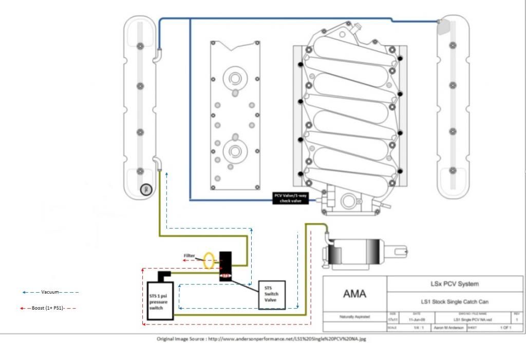
So, with just a by-the-book install of this kit, the switch valve/pressure switch allows clean air via vacuum from the TB to the valve cover. When the pressure switch detects > 1psi, it blocks off the port to valve cover and vents pressure to atmosphere. Given this default installation of STS, where would the catch can go ideally? On the dirty PCV lines before the PCV valve?

So, with just a by-the-book install of this kit, the switch valve/pressure switch allows clean air via vacuum from the TB to the valve cover. When the pressure switch detects > 1psi, it blocks off the port to valve cover and vents pressure to atmosphere. Given this default installation of STS, where would the catch can go ideally? On the dirty PCV lines before the PCV valve?
02-07-2014, 09:28 PM
#11
Pro
Thread Starter
Ok. Your issue is probably just a case of the lines not being large enough. I ran the small dual check valved triple port catch can from RX just the way your diagram shows and with the small lines they use, it just didn't cut it. I too was blowing the dipstick out under boost. It makes a big mess!! What you need to do is get some -8 lines and fittings and run one off the driver cover, one off the blower intake ( Checked) and one off the intake manifold (behind the throttle body (checked) and one of the rx checked breather caps on the oil fill spout. That should do you some good. Of course there are other ways but this way seems to be effective.
Also in your reference to blower intake, would the outlet on the TB suffice?
The PCV valve does have a check valve between it and the manifold.
I'm wondering if maybe the STS switch valve is failed, I'll have to check that...
02-07-2014, 09:41 PM
#12
Drifting

I no likey any of the diagrams you posted lol! But a million ways to do it so I'm not going to bother posting my way as its a dead horse subject and if you did a little searching via Google you would find some really good information on this subject. Good luck I'm sure you'll get it figured out.
02-07-2014, 10:00 PM
#13
Pro
Thread Starter
I no likey any of the diagrams you posted lol! But a million ways to do it so I'm not going to bother posting my way as its a dead horse subject and if you did a little searching via Google you would find some really good information on this subject. Good luck I'm sure you'll get it figured out.
 02-08-2014, 10:36 PM
#17
Melting Slicks
The problem with pic 2 is that I believe that port on the TB you are using as a vent should be seeing boost when the engine is making any. It would likely be feeding right into the crankcase the way it looks on the 2nd diagram. This would cause the stick to pop. This hose would normally run to an air filter "inlet" on a S/C which sees no pressure but with an STS I have no clue since that's all in the back.
The bypass to vent filter with the solenoid like in the first pic would negate this effect. However it looks like in the first pic, the can is backwards and also on the wrong line not really doing anything but stopping it up if it has a built in check valve.
The STS diagram uses the TB line as a vent only under vacuum and opens it up to a filter when it makes boost... This is how it looks at least.
You could probably do a combination of diagram 1 and 2 and make it work. The whole thing seems overly complicated.
Last edited by FixedRoof; 02-08-2014 at 10:39 PM.