
Rebuilding the Ghost, aka Great White
 02-09-2015, 05:30 PM
#201
Melting Slicks

Thread Starter


Sorry, it's already installed. Which one are you talking about? Any pictures?
 02-09-2015, 08:27 PM
#203
Drifting

I think you can do it on the car if you had a right angle drill. Anyway it's that aluminum boss that's about 2" forward and 1" down from the return port now. I believe they changed the location in 09 or 10. I know you have a better tr6060, but it can't hurt to get oil on that bearing and cluster. Good luck man the car should be a hoot.
http://smg.photobucket.com/user/Pumb...eight.jpg.html
Here is a good post from TJ at RPM
http://ls1tech.com/forums/manual-tra...-850-rwhp.html
http://smg.photobucket.com/user/Pumb...eight.jpg.html
Here is a good post from TJ at RPM
http://ls1tech.com/forums/manual-tra...-850-rwhp.html
Last edited by slow ride; 02-09-2015 at 08:34 PM.


 takes awhile to get used to tho lol
02-18-2015, 02:13 PM
takes awhile to get used to tho lol
02-18-2015, 02:13 PM
#206
Melting Slicks
Thread Starter
This past weekend, I was able to get a little more work accomplished.
First, I took a look at different options for the fuel rail fitment and plumbing.
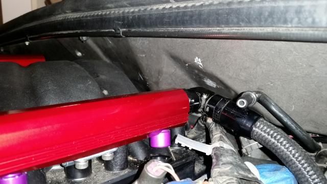
^ Here it is with the rails bolted down on just the brackets which would simulate LS7 injector height.
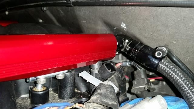
^ This picture shows a couple of ID1000 injectors in place without the adapter hats. This looked promising.
First, I took a look at different options for the fuel rail fitment and plumbing.

^ Here it is with the rails bolted down on just the brackets which would simulate LS7 injector height.

^ This picture shows a couple of ID1000 injectors in place without the adapter hats. This looked promising.
02-18-2015, 02:32 PM
#207
Melting Slicks
Thread Starter
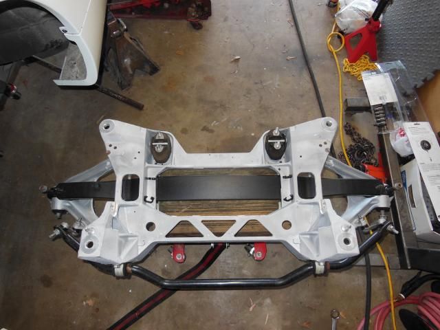
In order to get everything aligned and into place to further plan out final routing of other systems, I decided to install and bolt up the rear cradle. I figured this would be fairly easy, but it ended up being time consuming due to lack of good information on how much to remove from the rear cradle. I installed and removed everything about 6 times before it was finally bolted into place.
Here are the usual suspects due to the C5 drivetrain being about �� shorter than the C6 and not originally designed for a rear diff cooler.
-Differential contacts rear cradle on the right front corner
-The differential cooler line contacts the rear storage compartment on the C5
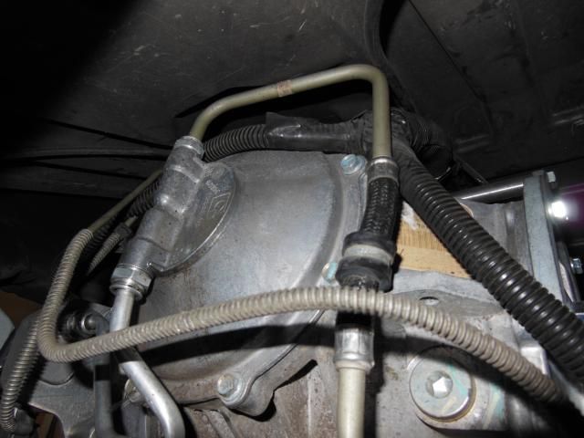
-The drain on the bottom of the differential hits the transverse leaf spring. I didn�t get any good pictures of this, but I have coil-overs so I just removed the rear leaf spring.
I won�t bore everyone with all of the different iterations of grinding pictures I took thinking "It's going to fit this time."
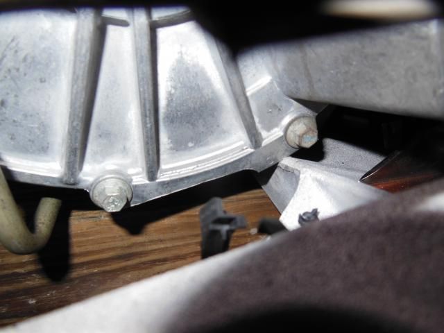
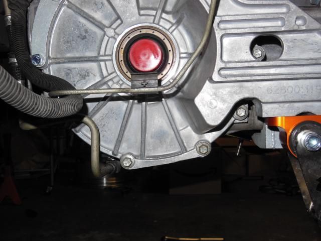
Excess metal on the right side diff cover looked early on like it might cause some issues so I laid out where it needed to be removed.
The box seemed to smile with approval�
Gone
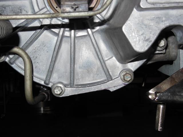
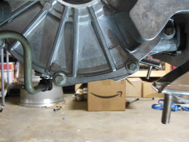
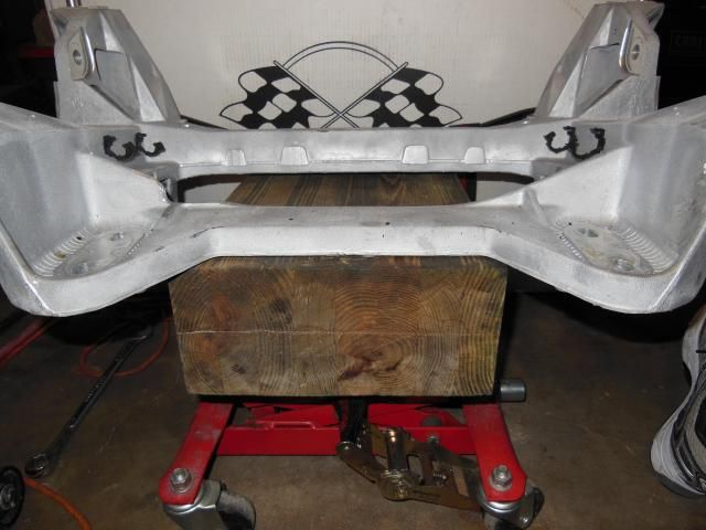
Here are the final modifications made to the rear cradle for everything to fit. I may have cut off a little more than needed, but I was tired of pulling the assembly in and out. I also figured out that initially the cradle must have been rotating upwards on the offset mounts and causing the cradle to make more contact than actual with the diff. This is probably one of the downfalls of doing this in the garage on jackstands using two small transmission jacks.
Here is where the cradle needed to be clearanced:


Here are the usual suspects due to the C5 drivetrain being about �� shorter than the C6 and not originally designed for a rear diff cooler.
-Differential contacts rear cradle on the right front corner

-The differential cooler line contacts the rear storage compartment on the C5

-The drain on the bottom of the differential hits the transverse leaf spring. I didn�t get any good pictures of this, but I have coil-overs so I just removed the rear leaf spring.
I won�t bore everyone with all of the different iterations of grinding pictures I took thinking "It's going to fit this time."
Excess metal on the right side diff cover looked early on like it might cause some issues so I laid out where it needed to be removed.

The box seemed to smile with approval�

Gone

Here are the final modifications made to the rear cradle for everything to fit. I may have cut off a little more than needed, but I was tired of pulling the assembly in and out. I also figured out that initially the cradle must have been rotating upwards on the offset mounts and causing the cradle to make more contact than actual with the diff. This is probably one of the downfalls of doing this in the garage on jackstands using two small transmission jacks.
Here is where the cradle needed to be clearanced:

 02-18-2015, 02:34 PM
#208
Melting Slicks
Thread Starter
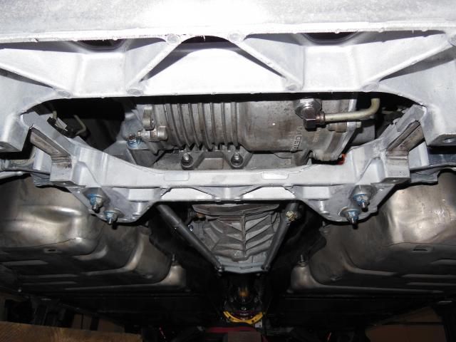
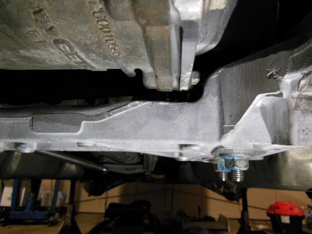
This shows the complete assembly installed and fully bolted up. I also skimmed off a few mils on the left side to accommodate the bolt head on the offset mount that I had to space out with washers. As usual, you move something to make clearance and sometimes it will come into contact with something else.

 02-18-2015, 02:40 PM
#209
Melting Slicks
Thread Starter
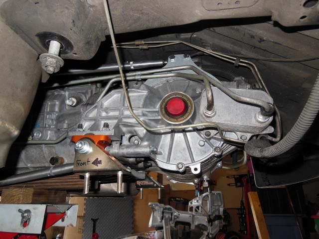
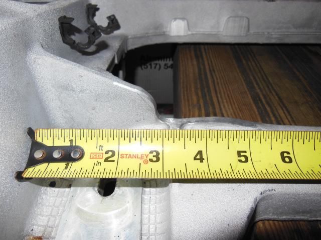
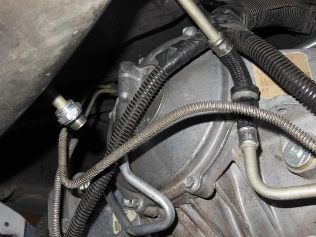
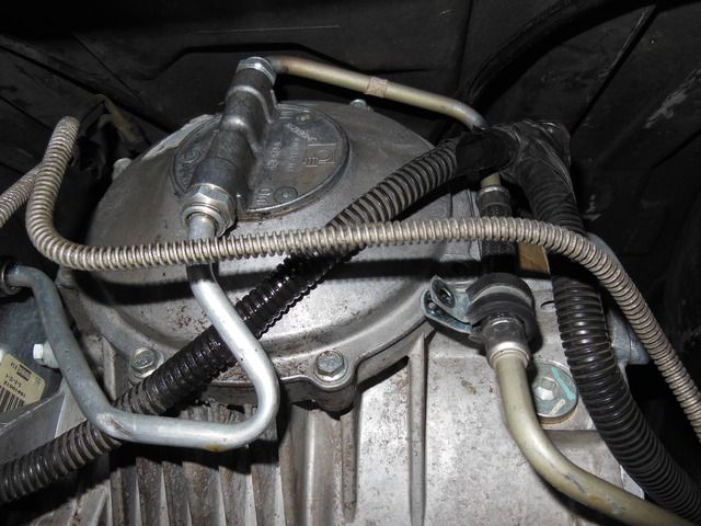
This is the amount of space between the top of the rear diff cooler ports and the storage compartment. I'm going to see if I can get a low profile 90 degree fitting to work and use -6AN hose to go from there to the bottom of the differential.
 02-18-2015, 07:44 PM
#211
Supporting Vendor

They call them all three and then some, so it makes it a bit of a PITA when searching for what you need.
How about Earls Part# AT949006
Jegs part# 361-AT949006

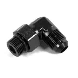
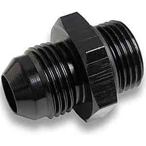
If you don't have the clearance, you will need to go with a straight and then into a 90 or whatever � fitting you need.
Here's the straight
Jegs part# 361-AT985006
Last edited by BLOWNBLUEZ06@RKT Performance; 02-18-2015 at 07:49 PM.
02-19-2015, 11:04 AM
#212
Melting Slicks
Thread Starter
Did you take any pictures? What type of welding method did you use and what filler rod?
Thanks, Bret. Good idea and this is the direction I'm thinking about going if there is enough room. I've also seen one person clock the rear cover and make the ports horizontal instead of vertical. I'm not sure what that entails yet.
Thanks, Bret. Good idea and this is the direction I'm thinking about going if there is enough room. I've also seen one person clock the rear cover and make the ports horizontal instead of vertical. I'm not sure what that entails yet.
02-19-2015, 11:14 AM
#213
Drifting
It was sort of a last minute thing as I wasn't expecting it. I actually mig welded it with clean up after the fact. They are an o ring type fitting so I don't expect any issues with higher frequency vibration, etc. I'm sure Jon could tig it for you in a few seconds. I believe is might be some sort of stainless steel and I just used a plumbing copper type cutting wheel to sever the line. If you use a fitting it needs to be a super tight 90 and adapt or make a new hose.
03-23-2015, 03:53 PM
#214
Melting Slicks
Thread Starter
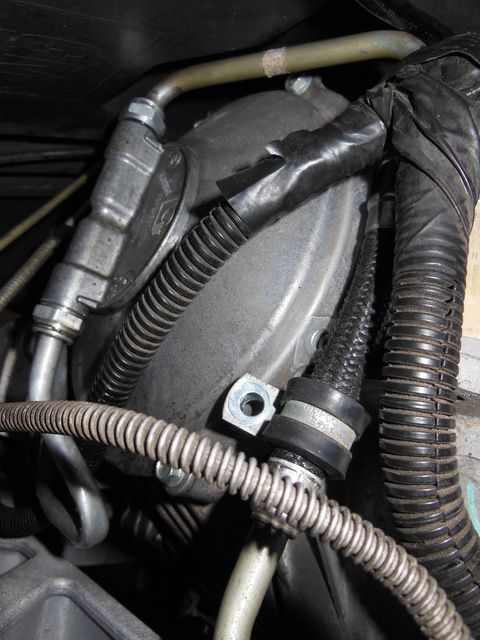
Still working on this thing as time permits. In late February, I had to re-route one of the knock sensor/cam extension harness, worked on installing some of the cold side charge piping, got the EBCM remounted to the cradle and fully bolted the front cradle back to the car.
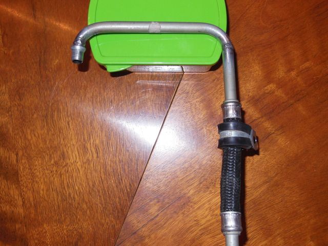
Next up was coming up with a solution for the rear diff cooler line. I really liked slow ride's solution and decided to see if it could be duplicated.
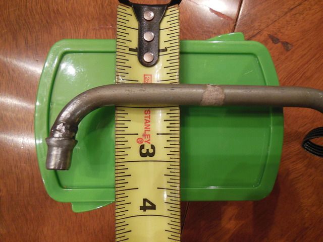
I took the old broken dipstick tube since it is about the same tubing diameter and bent it into shape for mock-up. It looked like it would work.
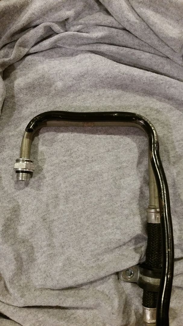
I did the measuring and cutting and a good friend of mine did the final prep and welding. Here's the finished product:
Fits like a glove.
Next up was coming up with a solution for the rear diff cooler line. I really liked slow ride's solution and decided to see if it could be duplicated.
I took the old broken dipstick tube since it is about the same tubing diameter and bent it into shape for mock-up. It looked like it would work.

I did the measuring and cutting and a good friend of mine did the final prep and welding. Here's the finished product:


Fits like a glove.


 03-23-2015, 07:09 PM
#218
Melting Slicks
Thread Starter
Thanks. Trying to stay motivated. It will be fun once it's complete.
Right before Spring Break, I was pressure washing the a/c condenser and this sticker came loose. I guess I can't claim that it's stock anymore.
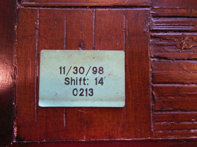
Right before Spring Break, I was pressure washing the a/c condenser and this sticker came loose. I guess I can't claim that it's stock anymore.
 03-23-2015, 07:26 PM
#219
Melting Slicks
Thread Starter
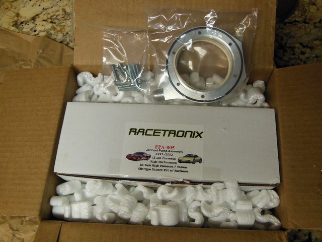
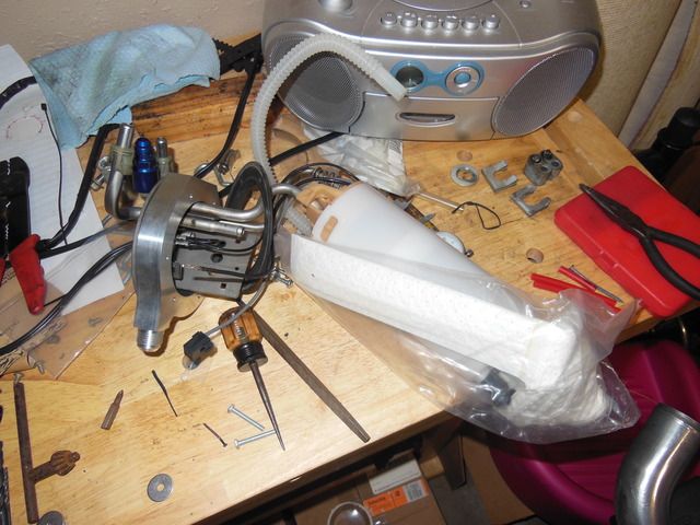
I finally drained the gas out of the tank this weekend in preparation for the ECS Fuel Ring install. Figured it would be a good time to install this new in box Racetronix 255 pump that had been sitting on the shelf for a few years.
While swapping the new pump to the old fuel hat the crimped and soldered connector pulled loose. This wire even had a QC sticker on it. Racetronix?!
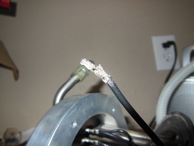
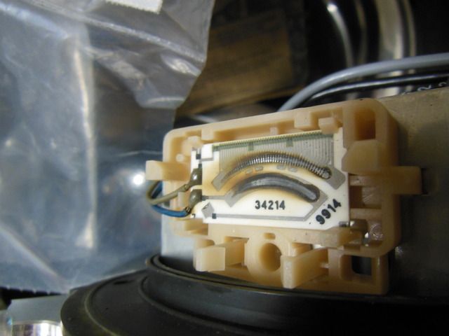
Look at these solder joints on the wires for the sending unit that were completed 16 years ago by GM. They are still connected.
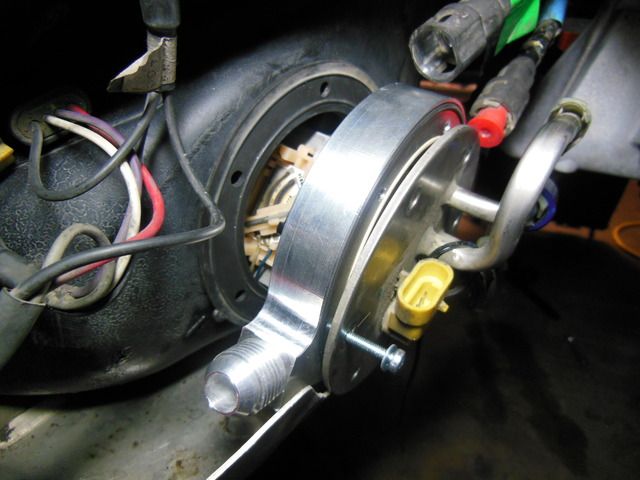
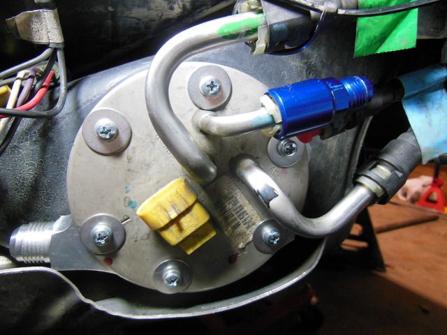
After a brief pause to repair a brand new part (racetronix wiring), the ECS fuel ring was installed without too much drama.
Of course, there was a trip to the hardware store for longer fasteners and "Hey, while you're out can you pick us up some dinner?"

While swapping the new pump to the old fuel hat the crimped and soldered connector pulled loose. This wire even had a QC sticker on it. Racetronix?!


Look at these solder joints on the wires for the sending unit that were completed 16 years ago by GM. They are still connected.

After a brief pause to repair a brand new part (racetronix wiring), the ECS fuel ring was installed without too much drama.
Of course, there was a trip to the hardware store for longer fasteners and "Hey, while you're out can you pick us up some dinner?"

