
Rebuilding the Ghost, aka Great White


 12-13-2016, 10:31 AM
#962
Melting Slicks

Thread Starter

Thanks. Almost feels like 3 builds in one.
The 5 year old Optima red top decided it wouldn't take anymore charges, but I was able to crank the car on Saturday after buying a new battery. It was great to finally hear it running again.
By Sunday, everything on the to-do list was complete.
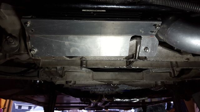
This oil cooler bracket needed a few modifications to make it fit.
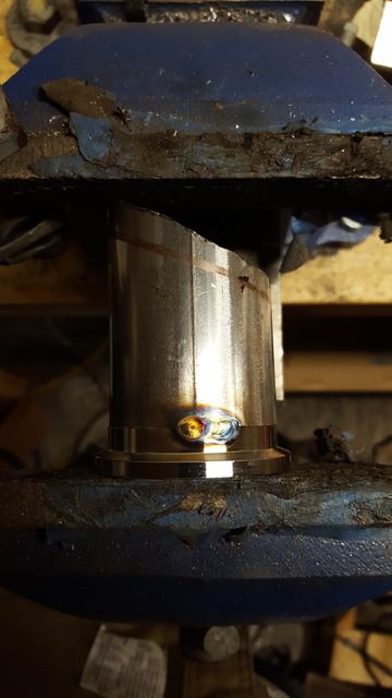
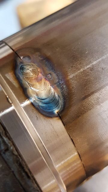
I finished out the day by making these short dump tubes for the wastegate outlets.
The 5 year old Optima red top decided it wouldn't take anymore charges, but I was able to crank the car on Saturday after buying a new battery. It was great to finally hear it running again.
By Sunday, everything on the to-do list was complete.
This oil cooler bracket needed a few modifications to make it fit.

I finished out the day by making these short dump tubes for the wastegate outlets.


The following users liked this post:
schpenxel (12-13-2016)
12-28-2016, 11:04 AM
#963
Melting Slicks
Thread Starter
I finally got to test the car on Sunday, 12/18/16 with the new 45mm wastegate setup and a 7# spring. It is somewhat louder with the new open gates, but boost control is still not there. It was creeping to 20 psi.  IAT temps were ~ 52 degrees, but I would have expected at least a flat curve and not more of the same.
Here's a log of the pull. This is with a 7# spring, manifold reference pressure to the side/bottom port and top of gate vented to atmosphere. NO BOOST CONTROLLER hooked up.

IAT temps were ~ 52 degrees, but I would have expected at least a flat curve and not more of the same.Here's a log of the pull. This is with a 7# spring, manifold reference pressure to the side/bottom port and top of gate vented to atmosphere. NO BOOST CONTROLLER hooked up.
 12-28-2016, 11:11 AM
#964
Melting Slicks
Thread Starter
Not to leave anything unchecked, I purchased a 3 psi spring and installed it. You can now push on the gate and open it fully using both thumbs.
Physical comparison of 3 psi vs 7 psi spring
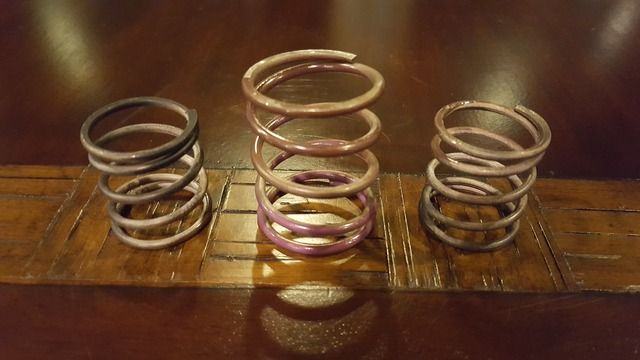
RPM----- 3# -- 7#
3000 --- 4.8 -- 8.4
3500 --- 5.8 -- 10.4
4000 --- 6.6 -- 12.4
4500 --- 8.5 -- 13.4
5000 -- 11.4 -- 15.4
5500 -- 15.4 -- 18.6
6000 -- 18.6 -- 20.6
6200 -- 18.9 -- 20.9
Physical comparison of 3 psi vs 7 psi spring

RPM----- 3# -- 7#
3000 --- 4.8 -- 8.4
3500 --- 5.8 -- 10.4
4000 --- 6.6 -- 12.4
4500 --- 8.5 -- 13.4
5000 -- 11.4 -- 15.4
5500 -- 15.4 -- 18.6
6000 -- 18.6 -- 20.6
6200 -- 18.9 -- 20.9
Last edited by Turbo-Geist; 12-28-2016 at 11:17 AM.
12-28-2016, 11:27 AM
#965
Melting Slicks
Thread Starter
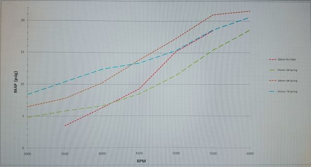
Here's a graph showing all of the comparisons to date.
1. Original gate configuration with the gate completely removed.
2. Original gate configuration with a 38mm gate and ~6# spring.
3. Modified gate location with a 45mm gate and 3# spring.
4. Modified gate location with a 45mm gate and 7# spring.
You can see that from 4000 rpm and up, the 45mm gate location with a 3# spring (green line) vents more exhaust than the 38mm location with no gate at all (red line).

Last edited by Turbo-Geist; 12-28-2016 at 11:28 AM.
12-28-2016, 11:30 AM
#966
Melting Slicks
Thread Starter
Any ideas on how to get this system to work like a turbocharger instead of a supercharger?

 12-28-2016, 12:00 PM
#968
Melting Slicks
Thread Starter
I mean I can buy a couple of flanges and make some tubes to eliminate these 45mm gates but the trend is going to be the same. Is there something in the data that suggests anything different?
These are brand new gates. I can open them by hand.
12-28-2016, 12:11 PM
#969
Le Mans Master

I'm too lazy to go dig them up but I'd like to see pics of how Joe (user_name) placed his holes in the housings. Only thing I can figure is your placement is still not an easier path for the air to take than continuing around the turbine blade.
https://www.corvetteforum.com/forums...post1593231605
I'm sure it may have posed a fitment issue but perhaps placing them closer to the turbine inlet and/or not at 90 degrees from the housing would have helped.
Just spit balling. Really bummed that this didn't work for you.
https://www.corvetteforum.com/forums...post1593231605
I'm sure it may have posed a fitment issue but perhaps placing them closer to the turbine inlet and/or not at 90 degrees from the housing would have helped.
Just spit balling. Really bummed that this didn't work for you.
12-28-2016, 12:27 PM
#970
Melting Slicks
Thread Starter
 12-28-2016, 12:58 PM
#971
Melting Slicks
Thread Starter
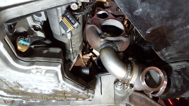
I think his passenger side placement is slightly better, but my driver side placement looks to be about the same.
Driver side
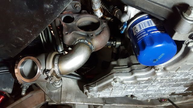
Passenger side
Driver side

Passenger side
 12-28-2016, 02:14 PM
#972
Melting Slicks
Thread Starter
At this point, it's looking like a pressure differential issue with a majority of the flow wanting to go out the turbine wheel instead of the wastegate. The only difference between my setup and some others is the lack of exhaust restriction post turbine. This combo essentially has 3" straight pipes.
Could this insert work to introduce some exhaust backpressure and gain control via the wastegate? Has anyone ever used these?

Could this insert work to introduce some exhaust backpressure and gain control via the wastegate? Has anyone ever used these?
 12-28-2016, 03:53 PM
#973
Melting Slicks
Remove the spring entirely from the gate so the poppet valve inside can simply open as far as physically possible within the gate itself to test
But 45mm gates should be able to vent enough to easily keep boost down.
Although if yours are the photos above, the discharge is half way around the scroll ? Certainly not ideal, they should have been placed before the scroll itself.
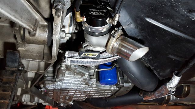
In post #962 you show a photo of a gate with 2 pipes connected to the top chamber ? What are they doing ? I cannot see any going to the bottom chamber to actually blow the gate open ?
At a push if you needed more flow to the gates....you could slice open the scroll on the turbo and link a passage closer to the inlet flange right to the gate tubing.
But 45mm gates should be able to vent enough to easily keep boost down.
Although if yours are the photos above, the discharge is half way around the scroll ? Certainly not ideal, they should have been placed before the scroll itself.
In post #962 you show a photo of a gate with 2 pipes connected to the top chamber ? What are they doing ? I cannot see any going to the bottom chamber to actually blow the gate open ?
At a push if you needed more flow to the gates....you could slice open the scroll on the turbo and link a passage closer to the inlet flange right to the gate tubing.
Last edited by stevieturbo; 12-28-2016 at 03:54 PM.
12-28-2016, 04:56 PM
#974
Melting Slicks
Wrong camshaft maybe? Possibly blowing boost out the tailpipes? Just asking,...since I have had it happen to me in the past...just not nearly as much "creep" as what you're seeing.
12-28-2016, 04:57 PM
#975
Melting Slicks
Thread Starter
Remove the spring entirely from the gate so the poppet valve inside can simply open as far as physically possible within the gate itself to test
But 45mm gates should be able to vent enough to easily keep boost down.
Although if yours are the photos above, the discharge is half way around the scroll ? Certainly not ideal, they should have been placed before the scroll itself.
In post #962 you show a photo of a gate with 2 pipes connected to the top chamber ? What are they doing ? I cannot see any going to the bottom chamber to actually blow the gate open ?
At a push if you needed more flow to the gates....you could slice open the scroll on the turbo and link a passage closer to the inlet flange right to the gate tubing.
Those are my pics. I could have placed the passenger side a little further up, but at some point you start hitting the starter on the passenger side and the frame rail on the driver side.
The housings shown that are bare with only the holes drilled in them are on StealthFRC's car and he is able to control to 13 psi. Same turbo kit and turbos, similar engine, but he has a 2.5" catback on his car. One theory is the backpressure from 2.5" pipes and mufflers causes enough restriction to make the exhaust flow towards the wastegate instead of through the turbine.
I ordered some materials today to delete the 45mm wastegates as a test, but I really don't think it will change what is happening.
The lines to the dome/top of the wastegate are to apply CO2 pressure. They were not hooked up for any of the tests. They were open to atmosphere. There is a line that senses manifold pressure attached to the bottom of the gates. It is not visible in the picture. When you apply 10 psi with the 3 psi spring installed, the valve becomes fully open.
Last edited by Turbo-Geist; 12-28-2016 at 04:58 PM.
12-28-2016, 04:57 PM
#976
Melting Slicks
Perhaps bad cam timing or bad tuning. I've heard of cases where heavily retarded timing has caused boost creep. But I've never experienced it myself and would imagine both would produce very obvious poor running symptoms even off boost.
12-28-2016, 05:02 PM
#977
Melting Slicks
Thread Starter
Does it seem to be wrong?
12-28-2016, 05:02 PM
#978
Melting Slicks
There really isn't any room on the TTiX kit to place the wastegates pre-turbine.
Those are my pics. I could have placed the passenger side a little further up, but at some point you start hitting the starter on the passenger side and the frame rail on the driver side.
The housings shown that are bare with only the holes drilled in them are on StealthFRC's car and he is able to control to 13 psi. Same turbo kit and turbos, similar engine, but he has a 2.5" catback on his car. One theory is the backpressure from 2.5" pipes and mufflers causes enough restriction to make the exhaust flow towards the wastegate instead of through the turbine.
I ordered some materials today to delete the 45mm wastegates as a test, but I really don't think it will change what is happening.
The lines to the dome/top of the wastegate are to apply CO2 pressure. They were not hooked up for any of the tests. They were open to atmosphere. There is a line that senses manifold pressure attached to the bottom of the gates. It is not visible in the picture. When you apply 10 psi with the 3 psi spring installed, the valve becomes fully open.
Are you saying it takes 10psi to fully open a wastegate with a 3psi spring ? Sounds rather high, although that should be venting a lot of air at that point.
I've 46mm Precisions on mine, BW 364FMW's on a 383ci motor and base 7psi spring gives 7psi with perfect control throughout.
My takeoff is on the manifold just prior to the turbo flange though and fairly well positioned using 45mm OD tubing.
Test it with no gates at all, and then test with the spring totally removed, but poppet valve still inside the gate.
Both free tests that require no parts.
Last edited by stevieturbo; 12-28-2016 at 05:03 PM.
12-28-2016, 05:04 PM
#979
Melting Slicks
Thread Starter
The timing is 14 degrees, A/F is in the 10.5 to 11.0 range. Car makes 1000rw on 18psi and idles and drives perfectly off boost.
12-28-2016, 05:07 PM
#980
Melting Slicks
Or as mentioned...whilst crude, slice open the scroll and add a half section of pipe or some sort of channel to allow more flow priority to the gate
Or you could at a push try and link the original gate discharge on the turbine housing to the gate pipe you have welded on.
Anything to help vent exhaust prior to the scroll itself.
Or you could at a push try and link the original gate discharge on the turbine housing to the gate pipe you have welded on.
Anything to help vent exhaust prior to the scroll itself.
Last edited by stevieturbo; 12-28-2016 at 05:07 PM.