
C5 Hydraulic Jack versus Jack Stand Positions; Wood Ramps and Wood Lifting ‘Pads’
 02-17-2006, 09:50 PM
#41
i'm a bit confused with the hockey puck,i am a technician and i will be using the shop lift most of the time,so far i understand the pucks are only used in the rear but what i want to know is do you simply place the puck in between the shop lifting pad and the vette's jacking location or do you need to bolt the pucks on to the car with bolts?
 02-17-2006, 10:31 PM
#42
Drifting

Member Since: Oct 2004
Location: Oakville ON "Real Corvettes have folding tops..."
Posts: 1,341
Likes: 0
Received 7 Likes
on
7 Posts

Good thing my old floor jack won't go under this thing anywhere. This scares me I didn't think it was so complcated.Thanks for the instructions. Can't imagine what will be the trick when I get it lowered. Guess if I can't get it off the ground won't be able to make the lowering adjustments.
02-18-2006, 12:53 AM
#43
Drifting
Thread Starter

Member Since: Sep 2003
Location: 1994 LT1 Coupe 6-speed with FX3 & 2000 LS1 Vert 6-Speed with F45 Hunterdon County, NJ
Posts: 1,363
Likes: 0
Received 5 Likes
on
5 Posts

Originally Posted by turboed
i'm a bit confused with the hockey puck,i am a technician and i will be using the shop lift most of the time,so far i understand the pucks are only used in the rear but what i want to know is do you simply place the puck in between the shop lifting pad and the vette's jacking location or do you need to bolt the pucks on to the car with bolts?
If your using a real rubber 'hockey puck', then yes, just place ONE between the "shop lifting pad" and the frame rail in the proper position on both rear shop lifting arm. Just pay close attention that it does not slip or move around, otherwise damage to the body panel could result.
If your using the GM or many aftermarket 'pucks' or made your own from a real rubber 'hockey puck' with a 'eye' installed, then their 'T' arrangement on top is inserted in the frame rail and rotated 90 degrees to 'lock' in place. Then the "shop Lifting pad" would be raised to contact the underside of the 'puck', clearing the body panel.
Given the two choices, I'd use a 'puck' that can 'lock' in place, since cars can shift a bit even on a stable lift, and a real rubber 'hockey puck' (without an 'eye' installed) would be flat and 'could' move around a bit, contacting the body panel with possible damage as a result.
Last edited by theadmiral94; 02-18-2006 at 12:58 AM.
02-18-2006, 01:03 AM
#44
Race Director

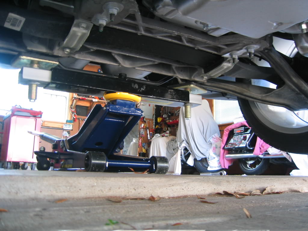
I followed the above thread, and constructed the lifting pads for the rear, front optional, and front preferred lifting sites. As I use Rhino ramps, I did not build the ramps.
I noticed, however, with the rear lifting pads, I did not get adequate overlap with the forward rib on the rear crossmember with the lifting pads flush with the ends of the 26" piece. I moved the outside pieces inward 2" and got a solid fit with good support on both of the ribs on the rear cross member.
Note the outside lifting pieces not flush with the edge of the 26" piece in the following photo...
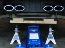
I like these lifting pads...would suggest following this thread's suggestions.
I noticed, however, with the rear lifting pads, I did not get adequate overlap with the forward rib on the rear crossmember with the lifting pads flush with the ends of the 26" piece. I moved the outside pieces inward 2" and got a solid fit with good support on both of the ribs on the rear cross member.
Note the outside lifting pieces not flush with the edge of the 26" piece in the following photo...
I like these lifting pads...would suggest following this thread's suggestions.
 02-19-2006, 01:35 PM
#46
Drifting
Thread Starter
Member Since: Sep 2003
Location: 1994 LT1 Coupe 6-speed with FX3 & 2000 LS1 Vert 6-Speed with F45 Hunterdon County, NJ
Posts: 1,363
Likes: 0
Received 5 Likes
on
5 Posts
To Gpotski:
Theadmiral94 1st reply - partial copy from our PM's),
I too was bothered by the upper pad not sitting evenly left to right, but was concerned about moving the upper pad inward and missing the outer 5-6 inch lifting zone specified in the manual. I just looked at my pad, I see it was contacting both ribs, but only about 2" thereof.
However, you mentioned missing the forward rib, so maybe I'm talking about a different concern.
Did you have the two 10" upper pads both perpendicular to the 26" and overlapping 3" rearward and 1.5" overlapping forward (so as to effectively change the 2x6 to a 2x10 only at the ends but with its center offset forward by 1.5")
If so, when you moved the upper 10" pad inward by 2" (assumed still maintaining the 1.5" & 3" overlapping), did it apply any lifting pressure to the straight-across portion of the cross-member (the section that does not have the upward portion supporting the body)?
Gpotski 1st reply (partial info copied from our PM's):
I just looked at the pads and it looks like the outside edges of the 10" upper pads are about 1" inside of the tie rod connection bolts when centered. The forward rib is then supported by the pads for a distance of about 2-3" on each side. I think this is the straight across portion of the crossmember you are talking about. That is the forward rib I was thinking needed to have some support too.
By the way, using the front preferred lifting pad, it doesn't seem to allow one to access the oil pan bolt to do an oil change. It looks like the lifting pad would get sprayed with oil, and it would be hard to get a socket onto the bolt. It seemed to me that the front optional would have to be used to do an oil change.
TheAdmiral94's 2nd reply (partial copy):
Moving the 10" pad 2" inboard does do a better job of supporting the cross-member and roughly doubles the contact surface area of the cross-member's front rib.
However, it also moves the center of the 10" pad very close to the inboard edge of GM's recommended lifting area.
Further, as the 26" piece will bend upward during lifting, it will most likely apply pressure on the inboard edge of the 10" upper lifting pad, which with the movement inboard by 2", would also moves the pressure 2" inboard of GM recommended lifting area.
The reason for the 26" board with the 10"x5.5" upper pad was my interpretation of the manual's 'criss-cross-hashed' lifting area of the rear cross-member, and that only the outer 5.5" was to be used.
This area is all outboard of the inside edge of the 45 degree angled area of the rear cross-member.
However, of that 5.5" outer area, most of it is upswept, thereby only allowing about 1.5" direct level contact with cross-member's forward rib. As I only attached the 10" piece to the 26" piece with one screw, it seems to self-adjust by tipping a bit to match the upswept area.
When I studied the cross-member, I took note of the upward swept part of the cross-member which supports the body and only extends upward from where the outer tie-rod connects to the cross-member.
The GM manual appears to be mostly concerned with upward bending (and thereby cracking) of the cross-member which could occur if lifted inboard of the outer 5.5" where it is not supported/supporting the body.
So in summary, you might be ok, but it would not conform to GM's recommendations.
BTW, regarding the preferred front cross-member lifting pad and it not providing clear access to the oil pan drain plug.
I'm not surprised by your observation, hence why I noted it "'may" provide access in the original write-up.
I had actually considered cutting a wide 'V', to match the shape of the preferred front cross-member to gain clearance for the plug. However,
since the 'preferred' front cross-member is not reachable with reasonably priced low-profile jacks (e.g. as recommended in my write-up), I only used the 'optional' cross-member for oil changes.
Using the 'preferred' cross-member generally requires first lifting at the 'optional' cross-member, setting two jack stands thereunder, then sliding further under the car and setting the 'preferred' pad (by either just setting it with jack stands or using the hydraulic jack to slightly lift the 'preferred' cross-member with the 'preferred' pad, and then repositioning the jack stands under the 'preferred' pad, and removing the 'optional' pad).
 03-02-2006, 06:48 AM
#48
Administrator


Member Since: Mar 2001
Location: In a parallel universe. Currently own 2014 Stingray Coupe.
Posts: 343,004
Received 19,302 Likes
on
13,975 Posts
C7 of the Year - Modified Finalist 2021
MO Events Coordinator
St. Jude Co-Organizer
St. Jude Donor '03-'04-'05-'06-'07-'08-'09-'10-'11-'12-'13-'14-'15-'16-'17-'18-'19-
'20-'21-'22-'23-'24
NCM Sinkhole Donor
CI 5, 8 & 11 Veteran


Good information here. Thanks.
03-02-2006, 01:46 PM
#49
Burning Brakes


The thing that scares me about the seeming complexity of lifting a C5 to work on it is:
1. Do the dealers know what they are doing?
2. Do they care enuff to take the time and necessary precautions to do it right?
I didn't buy my car new, and don't know how it was treated before it was mine, but now that it's mine, I tend to get real funny about having someone else work on it. There is no choice with warranty type work however.
I can tell you horror stories about "dealers" and "mechanics" working on previous cars (not Vettes) I have owned, grease on the seats and upholstery, scratched up fenders, alternator belt left off, etc., etc.
I just hate trusting "my baby" to someone else, but sometimes on these new sophisticated machines, you just can't do it all yourself.
Reckon I'll have to do some homework and find somebody who knows what they are doing on Vettes...and who cares. Any recommendations in the Harrisburg, PA area?
03-02-2006, 06:40 PM
#50
Instructor

Member Since: Aug 2004
Location: St. John Indiana
Posts: 235
Likes: 0
Received 0 Likes
on
0 Posts
God I feel like I need an engineer to just get my car up on jack stands so I can pull the wheels to get my calipers powder coated. I bock the rubber lifting puck that twist into place and had planned on jacking it up and putting the stands there for a week or two.
Can anyone discribe this in non mechanic terms I think?
Can anyone discribe this in non mechanic terms I think?
03-02-2006, 08:32 PM
#51
Drifting
Member Since: Oct 2004
Location: Oakville ON "Real Corvettes have folding tops..."
Posts: 1,341
Likes: 0
Received 7 Likes
on
7 Posts
[QUOTE=theadmiral94]In Other Words -- how to lift and support your C5 per the GM Manual
This article will translate and document the GM Manual’s procedures for lifting and supporting a C5 (based on a 2000) and clearly define the distinction between a ‘hydraulic jack’ and where it can be placed -- versus -- ‘jack stands’ and where they can be placed.[
I went back and re-read this and have copied it out to a word file for future reference. Thanks so much for this explanation it is extremely usefull to me.
03-02-2006, 08:34 PM
#52
Drifting
The best thing you can do is build a set of ramps and lifting cradles according to the theadmiral94 's instructions. I followed the suggestions, and added one more level to the front ramps. Then use the cradles with a floor jack, jack stands, etc. Works great, thanks to theadmiral94 for taking the time to figure this all out, and come up with a safe and easy solution.

Larry
62 Bel-Air 409
260 Eagle XP HP500EFI
2002 Corvette M6 Corvette
Larry
62 Bel-Air 409
260 Eagle XP HP500EFI
2002 Corvette M6 Corvette
03-03-2006, 04:50 PM
#53
Instructor
Member Since: Sep 2004
Location: Regina Sk
Posts: 129
Likes: 0
Received 0 Likes
on
0 Posts
What a great post. Thanks very much.
A few suggestions:
If you are going to change a tire, paint a caliper, or conduct some wheel well cleaning it is easier to just jack the car up using the puck and the hydraulic jack like you would any other car. If I am mistaken please let me know but this is what most newbie's and simple DIYs do.
If you are undertaking repairs or crawling under the car to put in your CAGS then you definitely need the stable effect of the jack stands in the proper place and this post is excellent
When you just made the huge investment on your new C5 it is a little overwhelming to read about all these special instructions.
My 2 cents on the dealers is don't trust them. Wanting to avoid problems in changing my runflats to Nitto 555's I took the baby into the dealer. They broke two of my tire sensors and scraped the entire undercarriage because the car jockey drove right up on the balancing machine without a care!
03-03-2006, 08:49 PM
#54
Burning Brakes
Member Since: Oct 2003
Location: Foresters Falls(near Ottawa) Ont
Posts: 1,106
Likes: 0
Received 1 Like
on
1 Post
Originally Posted by ram965
God I feel like I need an engineer to just get my car up on jack stands so I can pull the wheels to get my calipers powder coated. I bock the rubber lifting puck that twist into place and had planned on jacking it up and putting the stands there for a week or two.
Can anyone discribe this in non mechanic terms I think?
Can anyone discribe this in non mechanic terms I think?
Even sitting on the pucks, if I want into the car for something, the doors open and close no problem, hood and hatch work nicely, don't know if I'd lift the roof out though!!
RonJ ...
 03-03-2006, 09:39 PM
#55
Instructor
Member Since: Jun 2002
Location: El Segundo CA
Posts: 147
Likes: 0
Received 0 Likes
on
0 Posts
What would be the correct procedure for using a (symetric or asymetric) two post hoist?
If a hockey puck isn't used in front, what protects the body panels?
If a hockey puck isn't used in front, what protects the body panels?
Last edited by MolokaiBill; 03-03-2006 at 09:44 PM.
03-04-2006, 07:50 AM
#57
Burning Brakes
What about those little things that flip up on the ends of the lift arms? Wouldn't they accomplish the same thing as pucks?
Also, will a normal two post lift with swing arms clear and swing under a C5, or do you need to run the tires up on blocks first? I have access to one of these lifts and I'm thinking it would make doing my own oil changes etc. a lot easier...maybe, depending on the answers to the above.
Also, will a normal two post lift with swing arms clear and swing under a C5, or do you need to run the tires up on blocks first? I have access to one of these lifts and I'm thinking it would make doing my own oil changes etc. a lot easier...maybe, depending on the answers to the above.
03-04-2006, 09:12 AM
#58
Yellow C3/C5

Have any of you used this tool to span the rear cross member? I just found it while browsing the C6 General forum.
http://www.northerntool.com/webapp/...d=47686&R=47686
http://www.northerntool.com/webapp/...d=47686&R=47686
The following users liked this post:
Rocky48 (11-03-2018)
03-04-2006, 01:04 PM
#59
Instructor
Member Since: Aug 2004
Location: St. John Indiana
Posts: 235
Likes: 0
Received 0 Likes
on
0 Posts
Thanks decided to buy the lifting jack pads from Corvette America and got them today so I think I will jack it up and use those for the jack stands and see what happens.
03-06-2006, 09:29 PM
#60
Drifting
Thread Starter
Member Since: Sep 2003
Location: 1994 LT1 Coupe 6-speed with FX3 & 2000 LS1 Vert 6-Speed with F45 Hunterdon County, NJ
Posts: 1,363
Likes: 0
Received 5 Likes
on
5 Posts
To Mkiv808:
use a 'puck' (attaching type not just a flat rubber one) at each frame rail attachment point, one at a time with a hydraulic jack (however note that at only 5.5" +/- clearance before the 'puck' is installed, many normal jacks will not fit under the frame rail with the 'puck' installed. Then place a piece of wood above a jack-stand and place it below the outer edge of the associated cross-member (for safety -- never go underneath a car only supported by a hydraulic jack).
To JDs00PewterCoupe, rwsr50, FXSTDI, Bubbletop409, & DoomDRV:
Thanks for the compliments and glad this has helped.
To DoomDRV & RonJ:
Supporting the car with a hydraulic jack(s) one wheel or one axle at a time should be OK, but I nor GM recommend doing it with/at the 'puck' locations on the Frame Rails for extended time frames or supporting the whole car that way as possible damage may result.
Further, if the car is lifted by the 'puck' location, then where/how does one place a 'jack stand' in the same spot used for lifting? By contrast, constructing the wood 'lifting pads' creates a simple way and tool for both lifting with the jack (in the center) and supporting with 'jack stands' (at the outer ends), being both EASY and complying with GM's recommendations at the same time.
To MolokaiBill:
Assuming the two-post lift arms will fit under the car with a 'puck' in place in the rear, and assuming the two-post lift arm's front pad is flat (or can be made flat with a small piece of wood), then upon examination of the front frame rail 'puck' area, you will notice the body panel is not like the rear area -- i.e. the front frame-rail is not completely covered by the body panel -- it is uncovered forward and inward of the frame rail 'puck' area -- therefore, a flat front pad can be used without damage as long as it is placed long wise parallel with the car and inboard and forward or at the frame rail 'puck' location.
To rwsr50:
No, the 'flip up' on the end of the lift arms will not duplicate the 'puck' and will most likely cause damage, as it will concentrate all the car's weight on a smaller area than the hockey puck would provide, most likely resulting in damage to the frame rail and/or the rivets/welds that hold the 'puck' reinforcement plate inside the frame rails.
To VolFan615:
Nice tool find, however, albeit the color in the picture is different, assuming your link meant this entry (http://www.northerntool.com/webapp/w...ssearch=145883 The tool's specs indicate it to be 27 5/8" minimum width, which is too wide and would miss the correct lifting spots on our C5's (which are a maximum of 26" apart).
Also I can't tell their size from the picture, but the rubber pads would need to be at least 5.5" square to assure spanning of at least two ribs of the cross-member, so are they?
So, unless there is a narrower version, or it was modified to shorten both ends of the center 'box' by at least 1" each side, I wouldn't suggest it.