
The Grond Chronicles : Enter the Wideband... [Dialup: nap time]


 05-20-2006, 01:12 AM
#42
Supporting Tuner

Thread Starter

Originally Posted by shakainc
Keep practicing. Maybe we can tune my car someday.

 05-20-2006, 01:51 AM
#43
Drifting

Member Since: Oct 2004
Location: Southwest Virginia
Posts: 1,383
Likes: 0
Received 6 Likes
on
6 Posts

Man, that don't look like my wideband install. You must be doing something wrong! Or am I doing something wrong?
Good luck with the install! I really like like the LC1, I'm in the process of permanently installing dual LC1's, as well as a few other things.
Or am I doing something wrong? Good luck with the install!
I really like like the LC1, I'm in the process of permanently installing dual LC1's, as well as a few other things.
05-20-2006, 02:08 AM
#44
Supporting Tuner
Thread Starter
SpeedyZ 
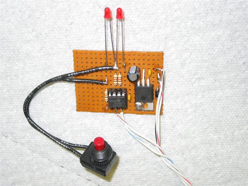
Looks very interesting - what's the circuit board with LEDs on the left column???
Post up with pics please. I would love to see what else you are installing. I see a roll cage is going in...
EG
Looks very interesting - what's the circuit board with LEDs on the left column???
Post up with pics please. I would love to see what else you are installing. I see a roll cage is going in...
EG
05-20-2006, 05:49 AM
#45

Originally Posted by SpeedyZ
Man, that don't look like my wideband install. You must be doing something wrong! Or am I doing something wrong?
Good luck with the install! I really like like the LC1, I'm in the process of permanently installing dual LC1's, as well as a few other things.
Or am I doing something wrong? Good luck with the install!
I really like like the LC1, I'm in the process of permanently installing dual LC1's, as well as a few other things.
05-20-2006, 07:52 AM
#46
Le Mans Master

Member Since: Sep 2003
Location: Farmington CT
Posts: 6,126
Received 160 Likes
on
125 Posts
Cruise-In VII Veteran

Originally Posted by SpeedyZ
Man, that don't look like my wideband install. You must be doing something wrong! Or am I doing something wrong?
Good luck with the install! I really like like the LC1, I'm in the process of permanently installing dual LC1's, as well as a few other things.
Or am I doing something wrong? Good luck with the install!
I really like like the LC1, I'm in the process of permanently installing dual LC1's, as well as a few other things.
05-20-2006, 08:10 AM
#47
Supporting Tuner
Thread Starter
Originally Posted by connecticut
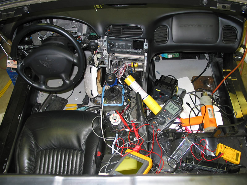
i see a couple high dollar Flukes, what's going on in there?
05-20-2006, 10:12 AM
#48
Drifting
Member Since: Oct 2004
Location: Southwest Virginia
Posts: 1,383
Likes: 0
Received 6 Likes
on
6 Posts
Wow, you guys are very observant! The Flukes are only for the install, they don't stay!
The little board is my LC1_Caltroller. It is a simple little circuit that controls the two calibrate/LED lines on my dual LC1 install. One thing I didn't like about the LC1 was the fact the LED stays on in normal operation and flashes off to warn of problems. So I made a little circuit that inverts the LED signal so the LEDs stays off until there is a problem then the LEDs will flash on. The best part is if the LC1 looses power the LED will stay lite really standing out and you know there is a problem, with the factory setup you will have to notice that the LED is not lite. But the main thing the circuit does is it allows both LC1's to be re-calibrated with one button. My plan is to have the button and LEDs mounted next to the AFR gauge in the pillar pod, so space will be limited so I didn't want to have two switches up there. This is the prototype. If anyone wants to build on let me know, I can get the diagram and chip to you.
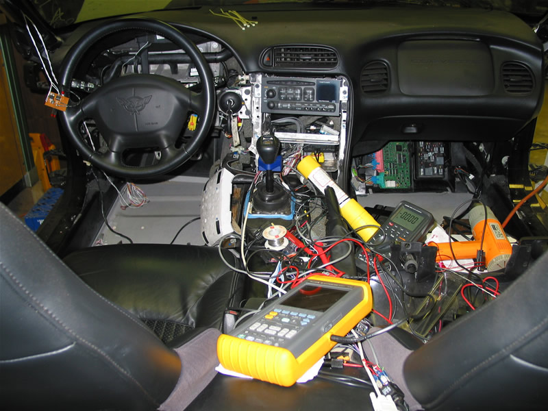
Among all the other stuff going in, I'm hardwiring my EFILive interface in the console so I don't have to have that big OBDII cable plugged under the dash. Also bringing the analog outputs from both LC1's to the console as well as the LC1 serial data stream. Hardwiring the Window Valet so it is not plugged on the ODBII port. The WV fits perfectly in a rib on top of the aluminum steering column frame, you can see the white tag on the WV in the photo below upper right inside the steering wheel at about 2 o'clock. There is quite a bite of room for extra stuff in these ribs! I'm running out of space for extra stuff so I have to look in all the nooks and crannies! I have installed a 12 pair (25 wire + shield) cable starting in the left fender well, goes inside under the dead pedal, over to the center console, over to the right side under the glove box, out to the right fender well above the PCM, up to the right front fender next to the brake scoop, over to the left front fender next to the brake scoop. So now I can trunk my cabling all over the car. A good example is my Accusump, I have a output that goes high when it goes active, I simply hook that to the wiring buss at the right front corner and pull if off in the left foot well under the dead pedal and run it up to the pillar pod where my LED indicator will be located. It makes running wires easy when you do it all at once. Will make hooking stuff up later a breeze too! You can see the wiring buss in the lower left foot well and right in front of the shifter. Can anyone spot the Innovate AUXBOX for G-force data logging?
The Flukes are only for the install, they don't stay! The little board is my LC1_Caltroller. It is a simple little circuit that controls the two calibrate/LED lines on my dual LC1 install. One thing I didn't like about the LC1 was the fact the LED stays on in normal operation and flashes off to warn of problems. So I made a little circuit that inverts the LED signal so the LEDs stays off until there is a problem then the LEDs will flash on. The best part is if the LC1 looses power the LED will stay lite really standing out and you know there is a problem, with the factory setup you will have to notice that the LED is not lite. But the main thing the circuit does is it allows both LC1's to be re-calibrated with one button. My plan is to have the button and LEDs mounted next to the AFR gauge in the pillar pod, so space will be limited so I didn't want to have two switches up there. This is the prototype. If anyone wants to build on let me know, I can get the diagram and chip to you.
Among all the other stuff going in, I'm hardwiring my EFILive interface in the console so I don't have to have that big OBDII cable plugged under the dash. Also bringing the analog outputs from both LC1's to the console as well as the LC1 serial data stream. Hardwiring the Window Valet so it is not plugged on the ODBII port. The WV fits perfectly in a rib on top of the aluminum steering column frame, you can see the white tag on the WV in the photo below upper right inside the steering wheel at about 2 o'clock. There is quite a bite of room for extra stuff in these ribs! I'm running out of space for extra stuff so I have to look in all the nooks and crannies! I have installed a 12 pair (25 wire + shield) cable starting in the left fender well, goes inside under the dead pedal, over to the center console, over to the right side under the glove box, out to the right fender well above the PCM, up to the right front fender next to the brake scoop, over to the left front fender next to the brake scoop. So now I can trunk my cabling all over the car. A good example is my Accusump, I have a output that goes high when it goes active, I simply hook that to the wiring buss at the right front corner and pull if off in the left foot well under the dead pedal and run it up to the pillar pod where my LED indicator will be located. It makes running wires easy when you do it all at once. Will make hooking stuff up later a breeze too! You can see the wiring buss in the lower left foot well and right in front of the shifter. Can anyone spot the Innovate AUXBOX for G-force data logging?