
ACA HID Install - Lotsa Pics
 01-26-2008, 10:41 PM
#1
Team Owner


Thread Starter
First of all, let me apologize for the pics of the dirty car you are about to view. This is Mrs. Patches' dd and the salt trucks have been a bit overzelous considering the minor snow fall we've had this month. It's been in the single digits temp-wise so a wash was out of the question before starting the install.
I recently posted a thread detailing the bulb jiggle fix.
http://forums.corvetteforum.com/show....php?t=1918423
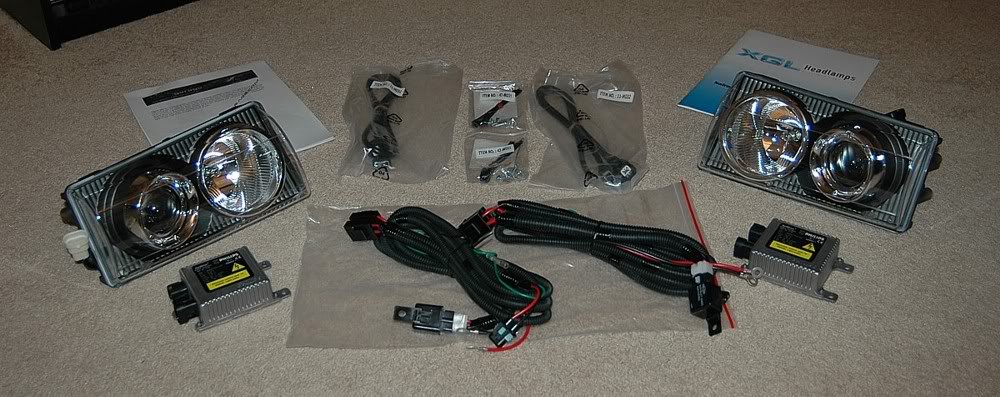
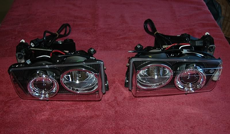
Here's a shot of the ACA HID kit I ordered from Corvette Garage.
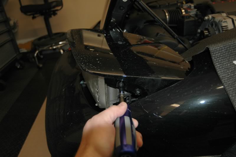
On to the install. First, I disconnected the negative battery cable. Then I removed the screws on the back of the headlight covers using a #20 Torx.
I removed two accessible screws to the headlight shrouds with lights still down.
Next, I removed the cover from the manual screw **** on both headlight motors and turned them to raise the headlight assemblies to their highest point.
I pulled up on the front of the headlight while raising it manually to make it easier to turn the ****.
Then I removed the final screw on the shrouds.
Pulled the shrouds off.
Removed the two side screws from each of the headlight covers.
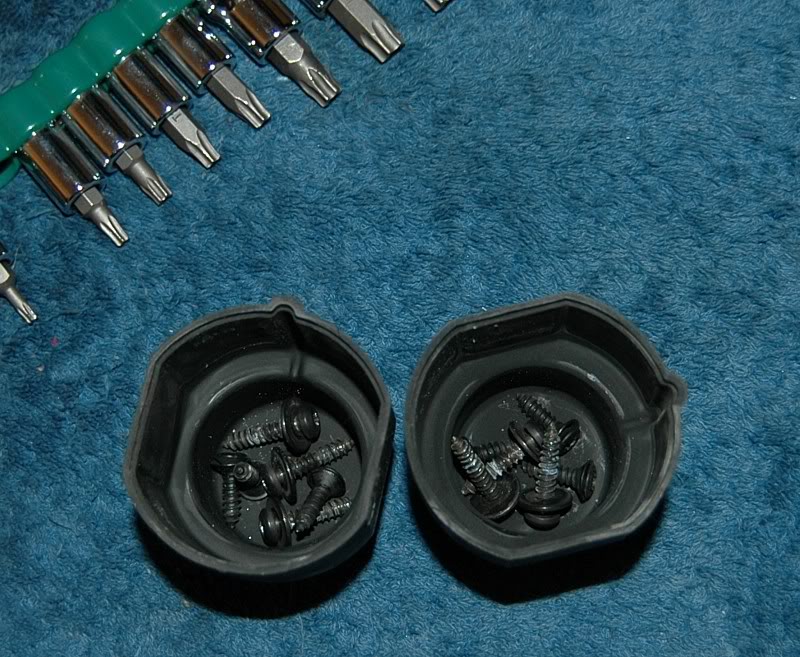
I stored the headlight hardware in the **** covers to keep from losing anything.
I recently posted a thread detailing the bulb jiggle fix.
http://forums.corvetteforum.com/show....php?t=1918423
Here's a shot of the ACA HID kit I ordered from Corvette Garage.
On to the install. First, I disconnected the negative battery cable. Then I removed the screws on the back of the headlight covers using a #20 Torx.
I removed two accessible screws to the headlight shrouds with lights still down.
Next, I removed the cover from the manual screw **** on both headlight motors and turned them to raise the headlight assemblies to their highest point.
I pulled up on the front of the headlight while raising it manually to make it easier to turn the ****.
Then I removed the final screw on the shrouds.
Pulled the shrouds off.
Removed the two side screws from each of the headlight covers.
I stored the headlight hardware in the **** covers to keep from losing anything.

The following users liked this post:
pmwilloughby (11-14-2017)
01-26-2008, 10:42 PM
#2
Team Owner
Thread Starter
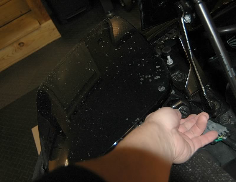
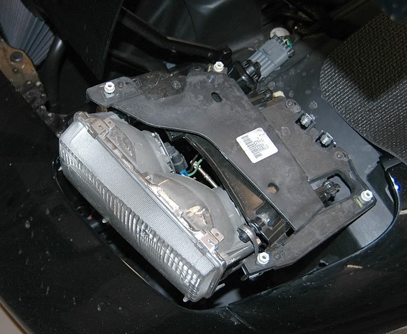
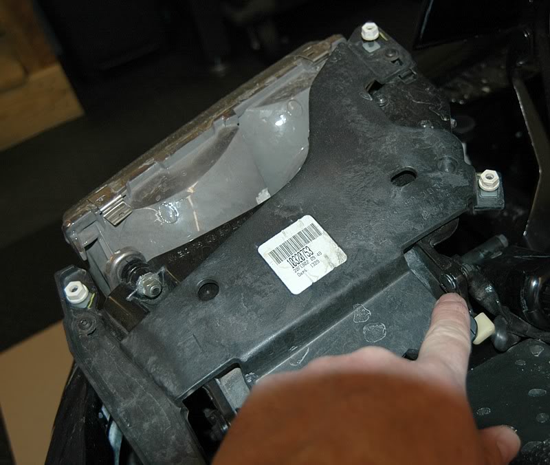
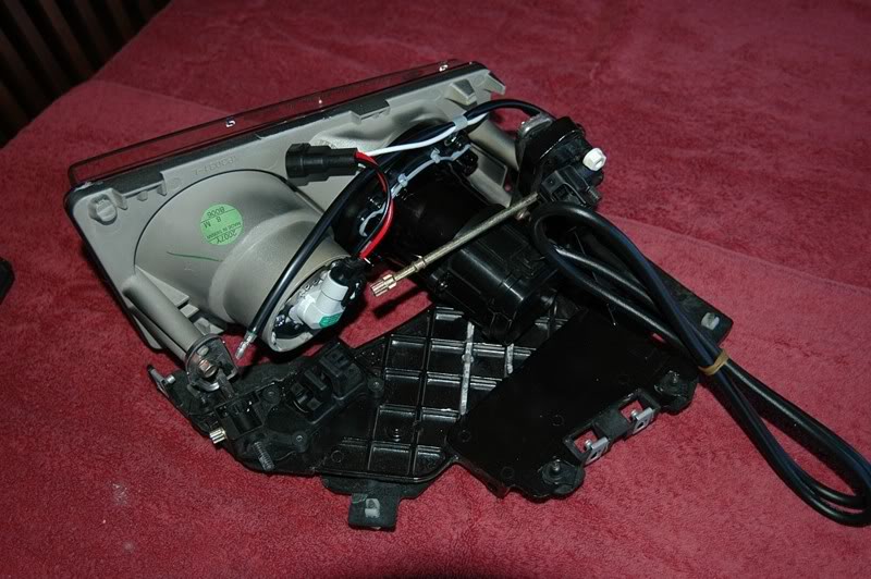
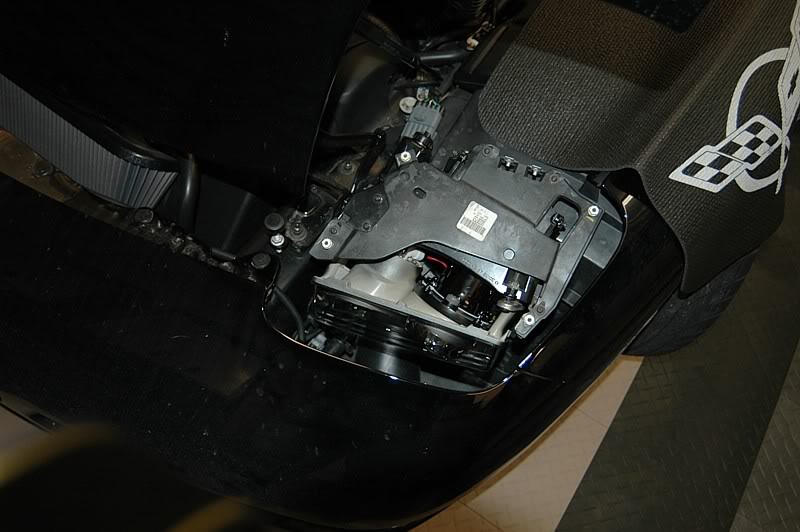
jdmvette had recommended removing the entire headlight assembly to make it easier to work on it so I decided to take his advice - it turns out to be a very good suggestion. Here's the headlight assembly ready for removal.
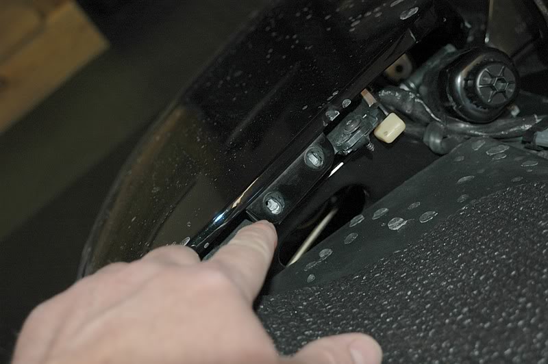
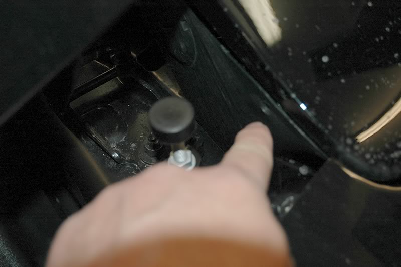
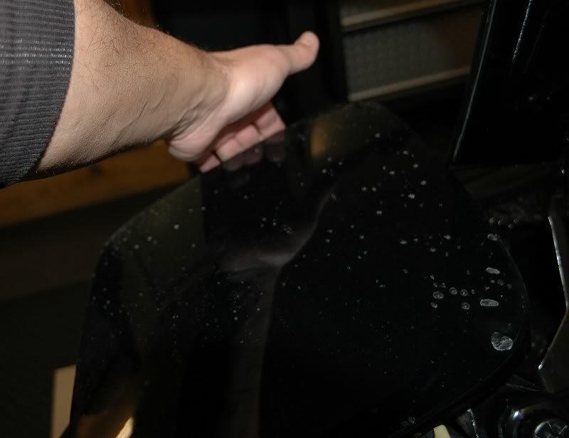
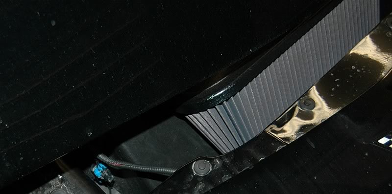
There are two bushed shoulder bolts held on with loctited nuts that needed to come out first. One here . . .
. . . and one there.
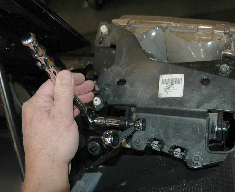
The bolts were locked in with blue loctite on this car so I had to be extremely careful unscrewing the bolts so as not to strip or break them. I used a small socket wrench and a ratcheted Torx bit and very carefully and slowly loosened them.
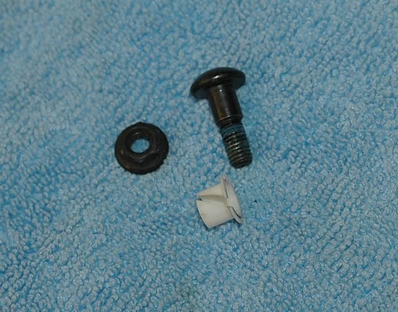
Here's a shot of the shoulder screw, bushing and nut from one of the hinge joints. Don't lose these!
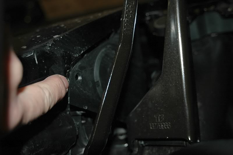
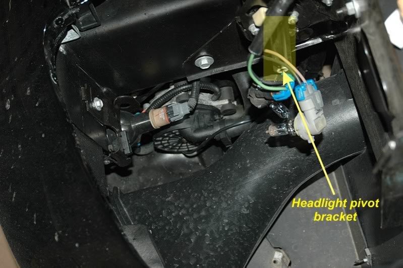
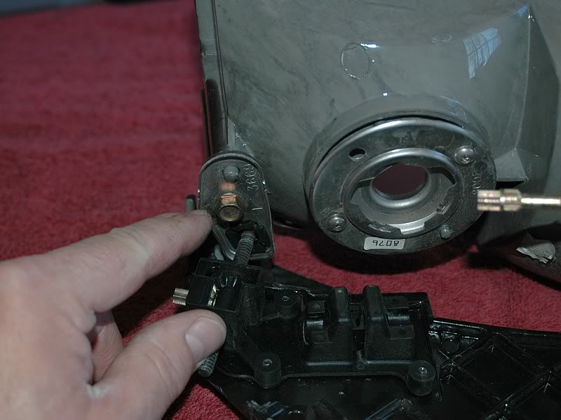
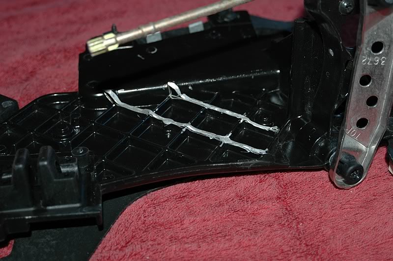
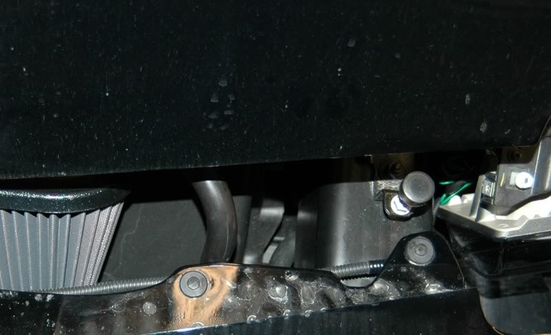
Once the rear hinges were free I could flip the headlights forward from the back, remove the electrical connectors from the rear of the lamp housings and expose the underside where there is a pin about 3/8" in diameter with a retaining washer that needs to be popped off so the pin can be extracted. This pin runs through the pivot bracket that is attached to the gearmotor that raises the headlight. I highlighted the pivot bracket below.
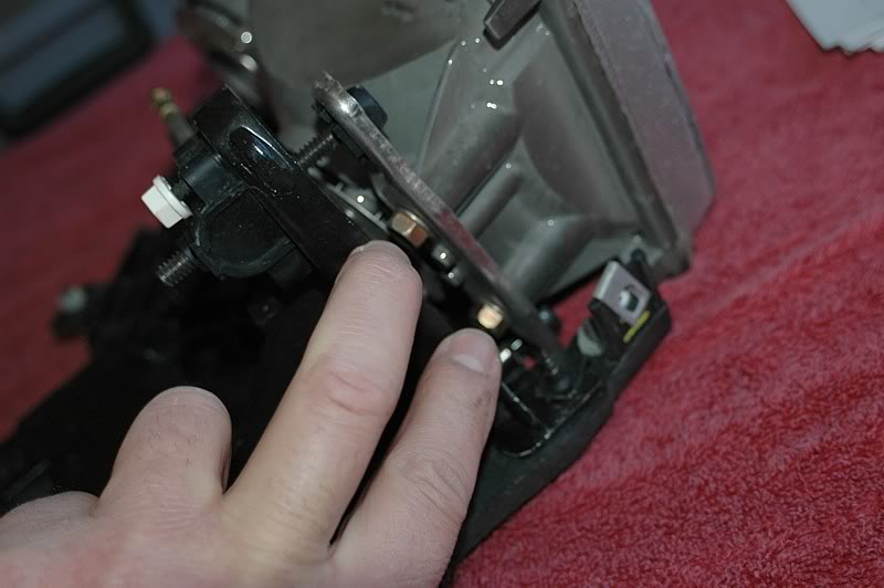
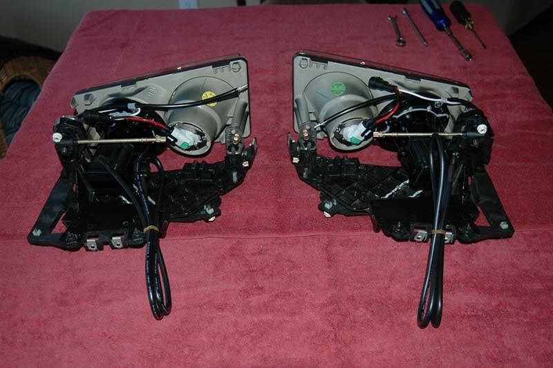
Once the headlights were out of the car, I took them inside to work on them at a table. The headlight bulb housings needed to come off at this point. Three screws hold them on - one here . . .
. . . and two here.
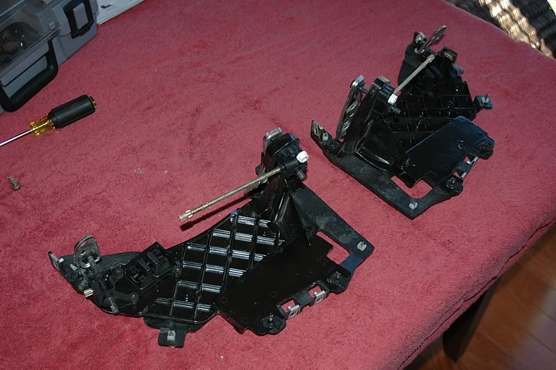
This left me with the bare brackets which needed a minor modification to create clearance for the HID's.
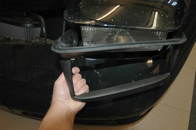
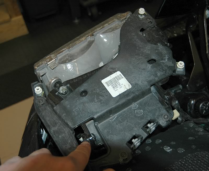
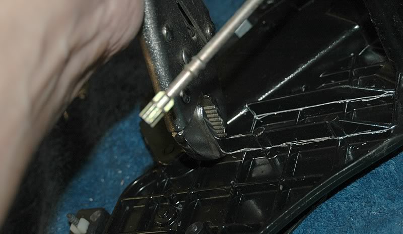
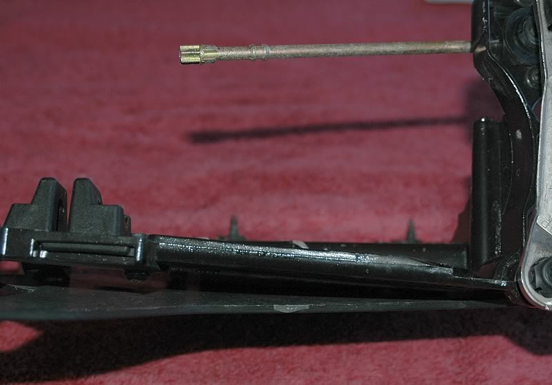
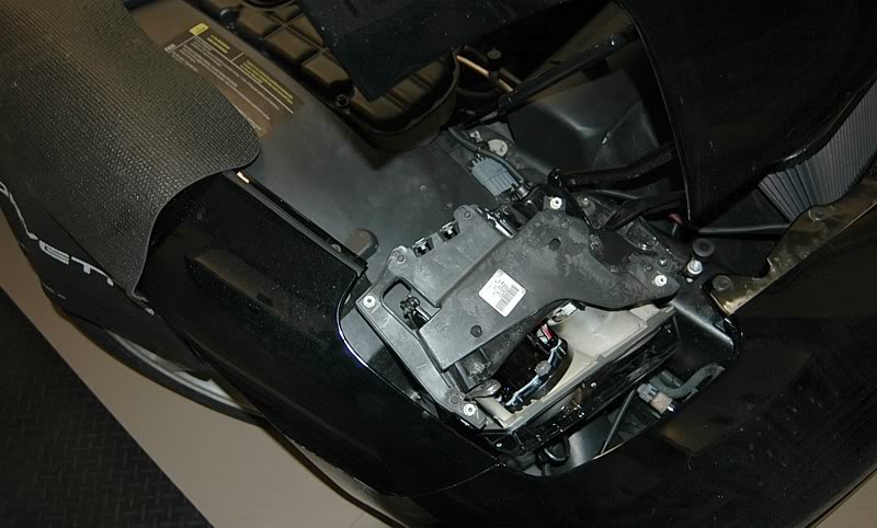
Incidentally, here are the adjusment mechanisms for the headlights.

There are two bushed shoulder bolts held on with loctited nuts that needed to come out first. One here . . .
. . . and one there.
The bolts were locked in with blue loctite on this car so I had to be extremely careful unscrewing the bolts so as not to strip or break them. I used a small socket wrench and a ratcheted Torx bit and very carefully and slowly loosened them.
Here's a shot of the shoulder screw, bushing and nut from one of the hinge joints. Don't lose these!
Once the rear hinges were free I could flip the headlights forward from the back, remove the electrical connectors from the rear of the lamp housings and expose the underside where there is a pin about 3/8" in diameter with a retaining washer that needs to be popped off so the pin can be extracted. This pin runs through the pivot bracket that is attached to the gearmotor that raises the headlight. I highlighted the pivot bracket below.
Once the headlights were out of the car, I took them inside to work on them at a table. The headlight bulb housings needed to come off at this point. Three screws hold them on - one here . . .
. . . and two here.
This left me with the bare brackets which needed a minor modification to create clearance for the HID's.
Incidentally, here are the adjusment mechanisms for the headlights.
01-26-2008, 10:42 PM
#3
Team Owner
Thread Starter
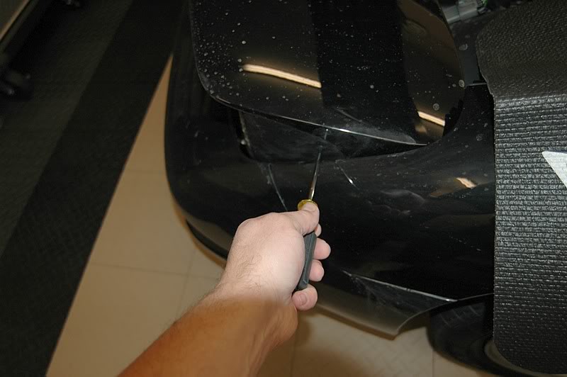
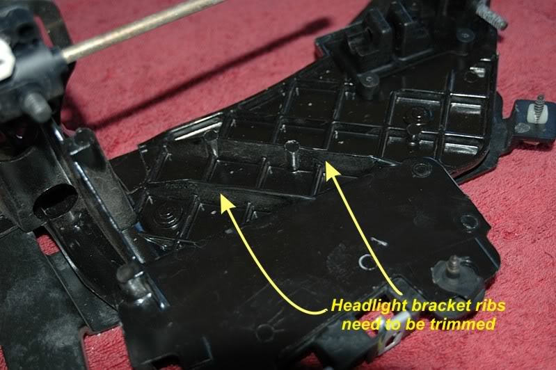
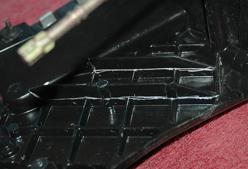
These two ribs that stand above the rest need to be cut down.
I scored the ribs with a sharp blade.
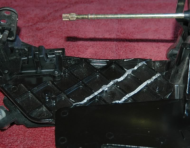
And used a set of vice grips to break small sections off until they were sufficiently reduced.
Here's the results.
I followed up with a Dremel to grind the edges off smooth.
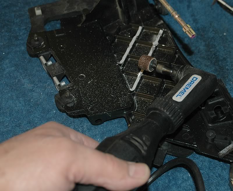
You can see the final result.
Looking from the edge, none of the ribs protrudes above the rest.
I then installed the HID housings onto the brackets. You need to be careful screwing the self-threading screws so as not to damage the plastic housing. I took my time and worked the screws in and out progressively to clear the plastic shavings out as I went.
Both housings mounted and ready for installation.
I scored the ribs with a sharp blade.
And used a set of vice grips to break small sections off until they were sufficiently reduced.
Here's the results.
I followed up with a Dremel to grind the edges off smooth.
You can see the final result.
Looking from the edge, none of the ribs protrudes above the rest.
I then installed the HID housings onto the brackets. You need to be careful screwing the self-threading screws so as not to damage the plastic housing. I took my time and worked the screws in and out progressively to clear the plastic shavings out as I went.
Both housings mounted and ready for installation.
01-26-2008, 10:43 PM
#4
Team Owner
Thread Starter
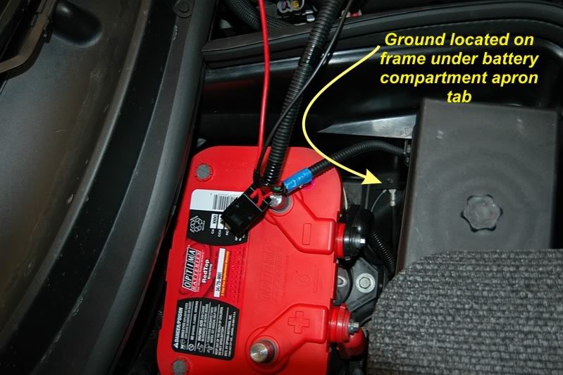
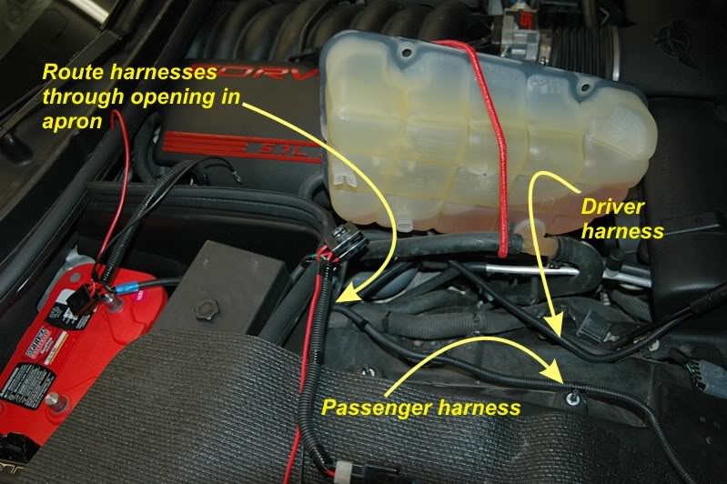
Next, I ran the harnesses along the passenger wheel well cover, under the coolant tank and into the battery compartment. The ground to use is under a tab in the shroud and is screwed into the frame. I removed the retainer in the cowl that holds the top of the shroud to it and popped the shroud tab loose from the ground stud. You need to tug it somewhat forcefully to get it off. Onec the ground screw was exposed, I removed the nut, pushed the black wire terminals from the harnesses onto it and installed the nut snugly. I then replaced the shroud to it's original position.
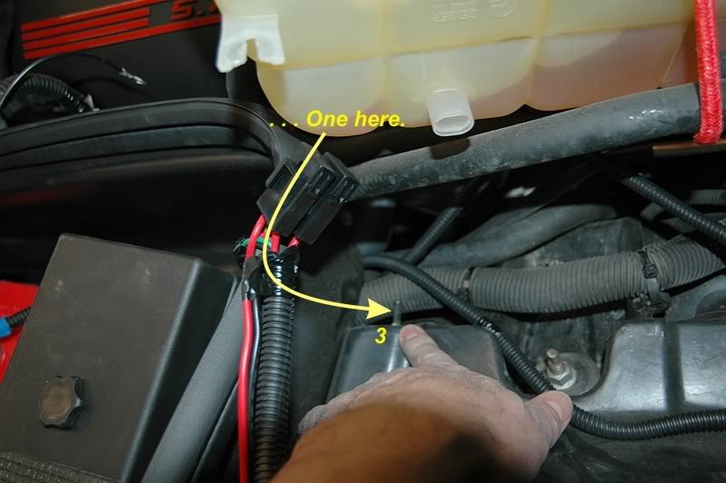
To make it easier to run the harnesses, I removed the three nuts from the coolant tank and rotated it over, holding out of the way with a bungee cord.
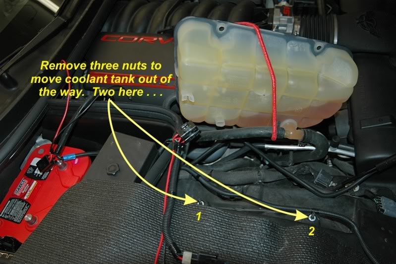
I ran the harnesses through a cutout in the bottom front of the shroud and then along the large harness under the coolant tank. I placed tie wraps around them but left them loose until I was almost done so they would be properly placed.
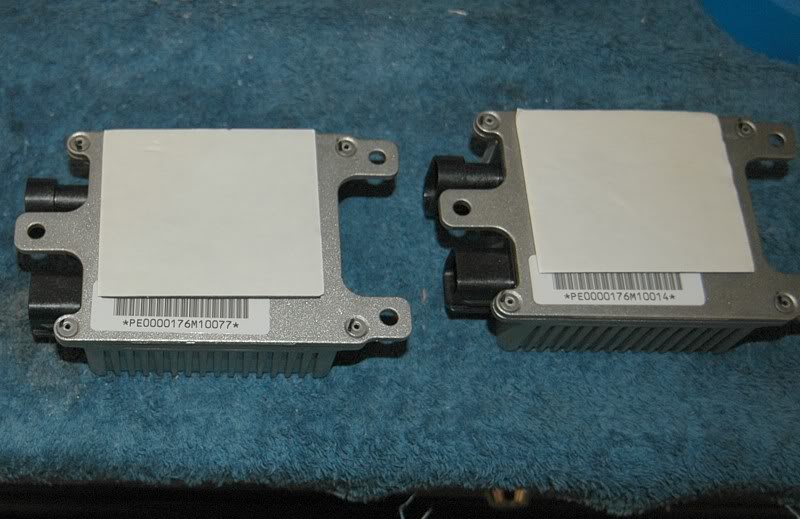
Next, I attached the double stick adhesive pads to the ballasts, being careful not to cover the bar codes or serial numbers for future reference and took pictures for documentation and so I don't have to remove them to get the numbers later if I need to.
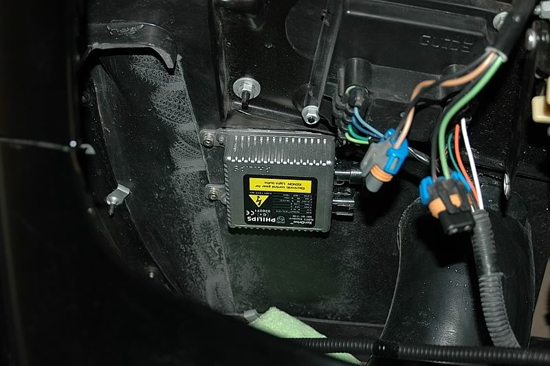
Using the adhesive pads, I attached the ballasts to the back wall of the headlight compartment, just under the bracket, and drilled holes through the wheel housing through the ballast mounting holes. I used some SS screws and nuts to permanently attach them.
Then I placed the headlight assemblies in the compartment loosely, taking care to wrap the lenses for protection. I pushed the harness connectors into the appropriate receivers on the ballasts and connected the OEM headlight connectors to the correct connectors on the HID housings. There is a black ground wire coming from the headlight that needed to be plugged into the green ground wire in the harness as well. I wrapped the harnesses and wiring up and out of the way with wire ties but left enough slack for the headlights to rotate up and down.
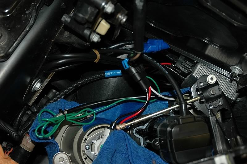
I ran the driver-side harness along the underside of the bumper cover lip and attached it using wire ties through the end of the push connectors that hold the bumper cover in place.
The next steps were a reversal of the headlamp removal process. I positioned them in place, reinserted the pivot pin through the housing and pivot bracket, pushing in the retainer washer after that. Then I replaced the shoulder bolts, bushings and nuts at the rear hinges using blue loctite to ensure they don't work loose. Once again, I was very careful screwing them in to avoid damage. Here's the driver's headlamp.
To make it easier to run the harnesses, I removed the three nuts from the coolant tank and rotated it over, holding out of the way with a bungee cord.
I ran the harnesses through a cutout in the bottom front of the shroud and then along the large harness under the coolant tank. I placed tie wraps around them but left them loose until I was almost done so they would be properly placed.
Next, I attached the double stick adhesive pads to the ballasts, being careful not to cover the bar codes or serial numbers for future reference and took pictures for documentation and so I don't have to remove them to get the numbers later if I need to.
Using the adhesive pads, I attached the ballasts to the back wall of the headlight compartment, just under the bracket, and drilled holes through the wheel housing through the ballast mounting holes. I used some SS screws and nuts to permanently attach them.
Then I placed the headlight assemblies in the compartment loosely, taking care to wrap the lenses for protection. I pushed the harness connectors into the appropriate receivers on the ballasts and connected the OEM headlight connectors to the correct connectors on the HID housings. There is a black ground wire coming from the headlight that needed to be plugged into the green ground wire in the harness as well. I wrapped the harnesses and wiring up and out of the way with wire ties but left enough slack for the headlights to rotate up and down.
I ran the driver-side harness along the underside of the bumper cover lip and attached it using wire ties through the end of the push connectors that hold the bumper cover in place.
The next steps were a reversal of the headlamp removal process. I positioned them in place, reinserted the pivot pin through the housing and pivot bracket, pushing in the retainer washer after that. Then I replaced the shoulder bolts, bushings and nuts at the rear hinges using blue loctite to ensure they don't work loose. Once again, I was very careful screwing them in to avoid damage. Here's the driver's headlamp.
01-26-2008, 10:43 PM
#5
Team Owner
Thread Starter
The passenger side.
Next, I connected the power to the headlights by removing the fuse box cover next to the battery, unscrewing the nut on the power post on the outboard side of the fuse box and placing the terminals onto the post before screwing the nut back on and replacing the cover. One minor problem I encountered here was that the terminal eyelet holes were too small to go onto the post so I had to cut them off and replace them with a slightly larger size. I used wire loom to protect the red power wire on the harness.
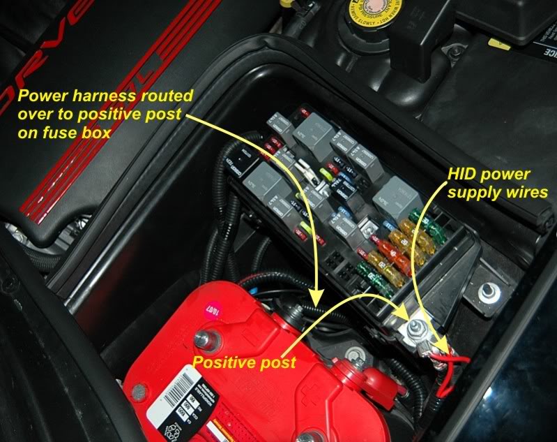
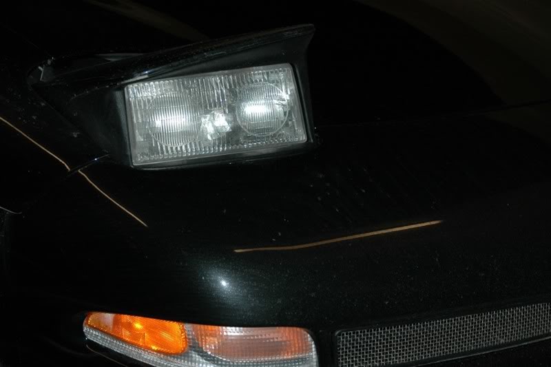
Finally, I reconnected the negatice battery cable and tested the headlights. They worked perfectly so I replaced the headlight covers and shrouds. Here's a shot of one of the headlights before the HID's.
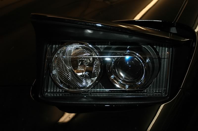
A shot of one after.
I took this pic before I started the installation. This is the stock headlights looking down my street.
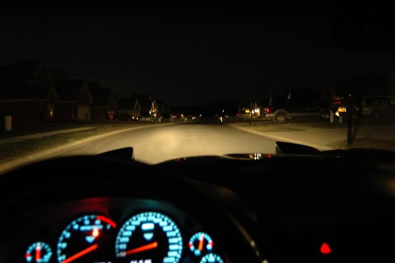
Here's a shot with the HID's looking down the same street.
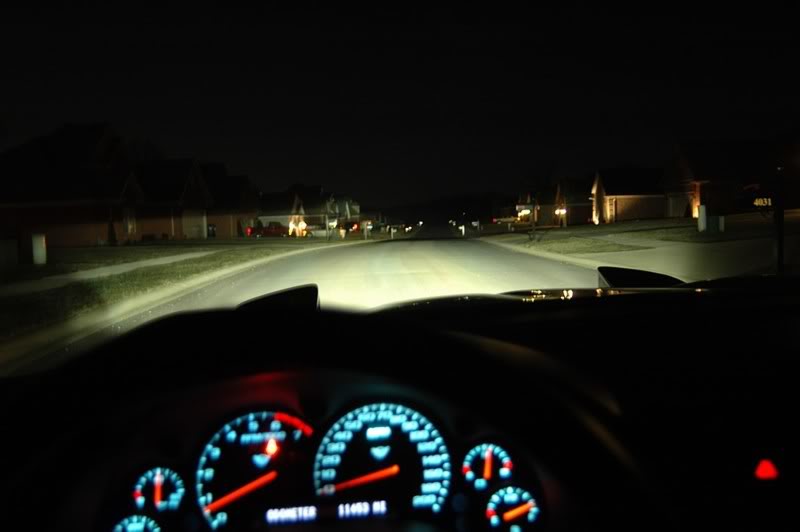
Without a doubt, the amount and quality of lighting these HID's provide is a huge improvement over the stock setup. I still need to do a bit of adjusting to get them aimed perfectly but the intial mounting put them very close to where they need to be. Now I just need to save up for a set for my own C5.
Next, I connected the power to the headlights by removing the fuse box cover next to the battery, unscrewing the nut on the power post on the outboard side of the fuse box and placing the terminals onto the post before screwing the nut back on and replacing the cover. One minor problem I encountered here was that the terminal eyelet holes were too small to go onto the post so I had to cut them off and replace them with a slightly larger size. I used wire loom to protect the red power wire on the harness.
Finally, I reconnected the negatice battery cable and tested the headlights. They worked perfectly so I replaced the headlight covers and shrouds. Here's a shot of one of the headlights before the HID's.
A shot of one after.
I took this pic before I started the installation. This is the stock headlights looking down my street.
Here's a shot with the HID's looking down the same street.
Without a doubt, the amount and quality of lighting these HID's provide is a huge improvement over the stock setup. I still need to do a bit of adjusting to get them aimed perfectly but the intial mounting put them very close to where they need to be. Now I just need to save up for a set for my own C5.
The following 3 users liked this post by Patches:
01-26-2008, 10:50 PM
#6
Melting Slicks


Wow very nice writeup everything looks very nice!! I want those lights but need to save up some money first. Just out of curiousity does the cutoff "shake" when you go over bumps?
01-26-2008, 10:58 PM
#8
Night Owl for life

Member Since: Nov 2003
Location: Bugs Bunny should'a made a left turn here
Posts: 23,195
Received 3,241 Likes
on
1,664 Posts

that's one helluva writeup! but then if it's coming from Patches, how could it be any less?


 01-27-2008, 01:46 AM
#12
Team Owner
Thread Starter
The lights are rock-solid during driving and don't exhibit any jiggling going over bumps so far. The jiggling fix I posted in the link above seems to be working.
01-27-2008, 02:04 AM
#13
Safety Car

Member Since: Jul 2007
Location: Louisville Kentucky
Posts: 4,333
Likes: 0
Received 6 Likes
on
4 Posts

Now those are my kind of instructions! 
Nice job patches. One thing I noticed in this picture:
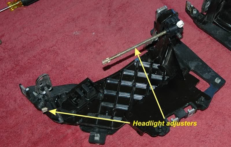
Your editing states that these are the height adjusting screws. If my memory of the manual serves me correct, the long one is for adjusting height and the short one is for horizontal adjustments. If I'm wrong, slap me and I'll shut up and sit down.
Again, nice write up!
Nice job patches. One thing I noticed in this picture:
Your editing states that these are the height adjusting screws. If my memory of the manual serves me correct, the long one is for adjusting height and the short one is for horizontal adjustments. If I'm wrong, slap me and I'll shut up and sit down.
Again, nice write up!
01-27-2008, 02:05 AM
#14
Race Director


Member Since: Apr 2007
Location: Ideals are peaceful...History is violent...St.Charles, MO.
Posts: 17,907
Received 439 Likes
on
228 Posts
2020 Corvette of the Year Finalist (appearance mods)
C5 of Year Winner (appearance mods) 2019
St. Jude Donor '08-'09-'12-'13-'14-'15-'16-'17-'18-'19-'20-'21-'22


Superb write-up with quality photo's
Those HID's look killer 
Those HID's look killer

 01-27-2008, 08:44 AM
#17
Melting Slicks
Member Since: Mar 2005
Location: Buckeye Country OH
Posts: 3,329
Likes: 0
Received 0 Likes
on
0 Posts
CI 6-7-8-9-10 Veteran
St. Jude Donor '05-'06-'07-'08
Great write up Ed!
Very cool mod, they look great. Bet Mrs. Patches will enjoy being able see better at night.
Very cool mod, they look great. Bet Mrs. Patches will enjoy being able see better at night.
01-27-2008, 09:11 AM
#18
Administrator

Member Since: Mar 2001
Location: In a parallel universe. Currently own 2014 Stingray Coupe.
Posts: 342,738
Received 19,234 Likes
on
13,933 Posts
C7 of the Year - Modified Finalist 2021
MO Events Coordinator
St. Jude Co-Organizer
St. Jude Donor '03-'04-'05-'06-'07-'08-'09-'10-'11-'12-'13-'14-'15-'16-'17-'18-'19-
'20-'21-'22-'23-'24
NCM Sinkhole Donor
CI 5, 8 & 11 Veteran

Excellent write up, Patches. Sure puts out a ton of light compared to the stock bulbs.

