
Back-Up lamp, fuse.
 06-28-2008, 11:25 AM
#1
Pro


Thread Starter
In my 2000 C5, in the under the hood fuse box , fuse 38 with the number 7866 on it. Does this pull out like any other fuse? My back-up lamps don't work and I have not incountered this type fuse, Circuit Breaker, Micro Relay, Mini Relay, Maxifuse, Maxi Circuit Breaker, Minifuse or whatever the hell they call it. Do you replace it, reset it, or pray to it? Sure could use some help please. Thanks.
 06-28-2008, 11:54 AM
#2
Burning Brakes


# 38 is actually your B/U lamp relay, it should pull straight up with a little wiggling. However, you should try fuse # 2(15amp) underhood first, it feeds your B/U lamp relay as well as your DRLs. Are the DRLs working?
Also fuse #21(10amp), in the passenger footwell, feeds your B/U light switch and your rearview mirror. Are the mirror electricals working properly?

Also fuse #21(10amp), in the passenger footwell, feeds your B/U light switch and your rearview mirror. Are the mirror electricals working properly?
Last edited by c5streak; 06-28-2008 at 11:56 AM.
06-28-2008, 12:00 PM
#3
Pro

In my 2000 C5, in the under the hood fuse box , fuse 38 with the number 7866 on it. Does this pull out like any other fuse? My back-up lamps don't work and I have not incountered this type fuse, Circuit Breaker, Micro Relay, Mini Relay, Maxifuse, Maxi Circuit Breaker, Minifuse or whatever the hell they call it. Do you replace it, reset it, or pray to it? Sure could use some help please. Thanks.
Good Luck
 06-28-2008, 12:32 PM
#5
Pro
Thread Starter
Fuse #2 and 21 are both good. DRLs and mirrows all work. The only thing not working on the car, that I can find, is the back-up lamps. I have not checked the bulbs because what are the chances both would go out at the same time? But it could have happened I guess. I will check them next. The lights were working a week to 10 days ago.


The following users liked this post:
thumpur (08-29-2016)
06-28-2008, 05:50 PM
#11
Burning Brakes
Switch is #14069600
No, the switch does not make ground for the bulbs, only triggers the relay. If you are getting power at the bulb and they are good, then check ground #401/splice 400 on the frame rail behind the LR tire.
06-28-2008, 05:56 PM
#12
Team Owner

Fuse #2 and 21 are both good. DRLs and mirrows all work. The only thing not working on the car, that I can find, is the back-up lamps. I have not checked the bulbs because what are the chances both would go out at the same time? But it could have happened I guess. I will check them next. The lights were working a week to 10 days ago.
 06-30-2008, 11:14 AM
#13
Pro
Thread Starter
Got a chance to check the bulbs this morning. No power to the bulbs and bulbs look good. That leaves the switch as the most likely problem. If I replace the switch, does it screw out of the case? Is it above the oil level of the transmission so I won't lose oil or make a mess? One other thing I noticed when I checked for power, the bulb (2057) has 2 filaments. Why do they need 2 filaments? I first thought it may serve as a license plate light but they are seperate.
I do thank you for your help.
I do thank you for your help.
06-30-2008, 11:19 AM
#14
Race Director


Got a chance to check the bulbs this morning. No power to the bulbs and bulbs look good. That leaves the switch as the most likely problem. If I replace the switch, does it screw out of the case? Is it above the oil level of the transmission so I won't lose oil or make a mess? One other thing I noticed when I checked for power, the bulb (2057) has 2 filaments. Why do they need 2 filaments? I first thought it may serve as a license plate light but they are seperate.
I do thank you for your help.
I do thank you for your help.
The 3057 have two filiments because they are used for stop and turn signal lights.
The following users liked this post:
glfrmrk (09-19-2017)
06-30-2008, 11:30 AM
#15
Pro
Thread Starter
Anthony, I got that number off the bulb when I took it out. I thought it was the wrong one also so I checked the book and it does call for 2057. Then I checked the license plate lights and it was easy to see that they were seperate from the back-ups.
06-30-2008, 11:48 AM
#16
Pro
Hi, did you test the relay? Below is the instructions to test the relay. Might be the switch, but should test the relay to rule that out. 2057 Bulb is the correct bulb, did you check continuity of the contacts on the bulb, sometimes they will fool you and look good and are not. or take a 9v battery and touch the wires to the bulb contacts, it should light dimly. Or you can touch wires from a 12 volt battery to the contacts, but be very careful to not cross the wires and short the system, or burn your fingers off..
Good Luck
++++++++++++++++++++++++++++++++++
To Test Relay
2, The number(s) below refer to the step number(s) on the diagnostic table.
3, Listen for an audible click when the Backup Lamp relay operates. Command both the ON and OFF states. Repeat the commands as necessary.
4, Tests for voltage at the coil side of the Backup Lamp relay. The APPROACH fuse supplies power to the coil side of the Backup Lamp relay.
5, Verifies that the BCM is providing ground to the Backup Lamp relay.
6, Tests if ground is constantly being applied to the Backup Lamp relay.
12, Tests for a short to voltage in the Backup Lamp control circuit.
When the BCM is replaced, use a scan tool to perform the BCM RPO Reprogram procedure. Refer to Body Control Module (BCM) Programming/RPO Configuration .
Step
Action
Value(s)
Yes
No
1
Did you perform the BCM Diagnostic System Check?
--
Go to Step 2
Go to Diagnostic System Check - Body Control System
2
Install a scan tool.
Turn ON the ignition, with the engine OFF.
With a scan tool, command the Backup Lamp relay ON and OFF.
Does the Backup Lamp relay turn ON and OFF with each command?
--
yes-Go to Diagnostic Aids
no-Go to Step 3
3
Turn OFF the ignition.
Disconnect the Backup Lamp relay.
Turn ON the ignition, with the engine OFF.
Probe the coil side feed circuit of the Backup Lamp relay with a test lamp that is connected to a good ground. Refer to Power Distribution Schematics in Wiring Systems for electrical center circuit identification.
Does the test lamp illuminate?
--
yes- Go to Step 4
no-Go to Step 10
4
Connect a test lamp between the control circuit of the Backup Lamp relay and the coil side feed circuit of the Backup Lamp relay. Refer to Power Distribution Schematics in Wiring Systems for electrical center circuit identification.
With a scan tool, command the Backup Lamp relay ON and OFF .
Does the test lamp turn ON and OFF with each command?
--
yes-Go to Step 8
no-Go to Step 5
5
Does the test lamp remain illuminated with each command?
--
yes-Go to Step 7
no-Go to Step 6
6
Test the control circuit of the Backup Lamp relay for a short to voltage. Refer to Circuit Testing and Wiring Repairs in Wiring Systems.
Did you find and correct the condition?
--
yes-Go to Step 13
no-Go to Step 9
7
Test the control circuit of the Backup Lamp relay for a short to ground. Refer to Circuit Testing and Wiring Repairs in Wiring Systems.
Did you find and correct the condition?
--
yes-Go to Step 13
no-Go to Step 9
8
Inspect for poor connections at the Backup Lamp relay. Refer to Testing for Intermittent and Poor Connections and Connector Repairs in Wiring Systems.
Did you find and correct the condition?
--
Go to Step 13
Go to Step 11
9
Inspect for poor connections at the harness connector of the BCM. Refer to Testing for Intermittent and Poor Connections and Connector Repairs in Wiring Systems.
Did you find and correct the condition?
--
Go to Step 13
Go to Step 12
10
Repair the coil side feed circuit of the Backup Lamp relay. Refer to Wiring Repairs in Wiring Systems.
Did you complete the repair?
--
Go to Step 13
--
11
Replace the Backup Lamp relay.
Did you complete the replacement?
--
Go to Step 13
--
12
Important
Perform the BCM RPO Reprogram procedure. Refer to Body Control Module (BCM) Programming/RPO Configuration .
Replace the BCM. Refer to Body Control Module Replacement .
Did you complete the replacement?
--
Go to Step 13
--
13
Use the scan tool in order to clear the DTCs .
Operate the vehicle within the Conditions for Setting the DTC as specified in the supporting text.
Does the DTC reset?
++++++++++++++++++++++++++++++++++
If you determine that switch is bad SEE BELOW for replacement.
TO DETERMINE SEE BELOW
Connect a fused jumper wire between:
the back up lamp (manual) switch connector terminal A and terminal B.
the park neutral position (auto) switch connector C1 terminal C and terminal F.
Connect a test light from the back up lamp switch circuit 1524 relay terminal in the underhood electrical center and ground.
Does the test light illuminate?
--
Go to Step 12
Go to Step 11
11
Repair the open or high resistance in back up lamp switch circuit 1524.
Is the repair complete?
--
Go to Step 18
--
12
Replace the back up lamp switch (manual) or the park neutral position switch (auto). Refer to Backup Lamp Switch Replacement or Park/Neutral Position Switch Replacement .
Is the repair complete?
--
Go to Step 18
================================
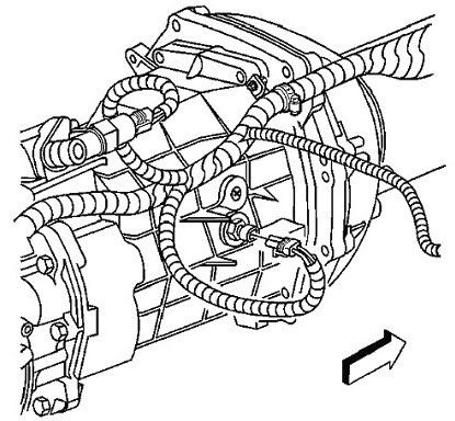
Backup Lamp Switch Replacement
Removal Procedure
Raise and suitably support the vehicle. Refer to Lifting and Jacking the Vehicle in General Information.
Remove the intermediate exhaust pipe. Refer to Intermediate Pipe Replacement in Engine Exhaust.
Disconnect the backup lamp switch electrical connector.
Remove the backup lamp switch.
Installation Procedure
Notice
Use the correct fastener in the correct location. Replacement fasteners must be the correct part number for that application. Fasteners requiring replacement or fasteners requiring the use of thread locking compound or sealant are identified in the service procedure. Do not use paints, lubricants, or corrosion inhibitors on fasteners or fastener joint surfaces unless specified. These coatings affect fastener torque and joint clamping force and may damage the fastener. Use the correct tightening sequence and specifications when installing fasteners in order to avoid damage to parts and systems.
Install the backup lamp switch. Tighten
Tighten the backup lamp switch to 20 N�m (15 lb ft).
Connect the backup lamp switch electrical connector.
Install the intermediate exhaust pipe. Refer to Intermediate Pipe Replacement in Engine Exhaust.
Lower the vehicle.
Good Luck
++++++++++++++++++++++++++++++++++
To Test Relay
2, The number(s) below refer to the step number(s) on the diagnostic table.
3, Listen for an audible click when the Backup Lamp relay operates. Command both the ON and OFF states. Repeat the commands as necessary.
4, Tests for voltage at the coil side of the Backup Lamp relay. The APPROACH fuse supplies power to the coil side of the Backup Lamp relay.
5, Verifies that the BCM is providing ground to the Backup Lamp relay.
6, Tests if ground is constantly being applied to the Backup Lamp relay.
12, Tests for a short to voltage in the Backup Lamp control circuit.
When the BCM is replaced, use a scan tool to perform the BCM RPO Reprogram procedure. Refer to Body Control Module (BCM) Programming/RPO Configuration .
Step
Action
Value(s)
Yes
No
1
Did you perform the BCM Diagnostic System Check?
--
Go to Step 2
Go to Diagnostic System Check - Body Control System
2
Install a scan tool.
Turn ON the ignition, with the engine OFF.
With a scan tool, command the Backup Lamp relay ON and OFF.
Does the Backup Lamp relay turn ON and OFF with each command?
--
yes-Go to Diagnostic Aids
no-Go to Step 3
3
Turn OFF the ignition.
Disconnect the Backup Lamp relay.
Turn ON the ignition, with the engine OFF.
Probe the coil side feed circuit of the Backup Lamp relay with a test lamp that is connected to a good ground. Refer to Power Distribution Schematics in Wiring Systems for electrical center circuit identification.
Does the test lamp illuminate?
--
yes- Go to Step 4
no-Go to Step 10
4
Connect a test lamp between the control circuit of the Backup Lamp relay and the coil side feed circuit of the Backup Lamp relay. Refer to Power Distribution Schematics in Wiring Systems for electrical center circuit identification.
With a scan tool, command the Backup Lamp relay ON and OFF .
Does the test lamp turn ON and OFF with each command?
--
yes-Go to Step 8
no-Go to Step 5
5
Does the test lamp remain illuminated with each command?
--
yes-Go to Step 7
no-Go to Step 6
6
Test the control circuit of the Backup Lamp relay for a short to voltage. Refer to Circuit Testing and Wiring Repairs in Wiring Systems.
Did you find and correct the condition?
--
yes-Go to Step 13
no-Go to Step 9
7
Test the control circuit of the Backup Lamp relay for a short to ground. Refer to Circuit Testing and Wiring Repairs in Wiring Systems.
Did you find and correct the condition?
--
yes-Go to Step 13
no-Go to Step 9
8
Inspect for poor connections at the Backup Lamp relay. Refer to Testing for Intermittent and Poor Connections and Connector Repairs in Wiring Systems.
Did you find and correct the condition?
--
Go to Step 13
Go to Step 11
9
Inspect for poor connections at the harness connector of the BCM. Refer to Testing for Intermittent and Poor Connections and Connector Repairs in Wiring Systems.
Did you find and correct the condition?
--
Go to Step 13
Go to Step 12
10
Repair the coil side feed circuit of the Backup Lamp relay. Refer to Wiring Repairs in Wiring Systems.
Did you complete the repair?
--
Go to Step 13
--
11
Replace the Backup Lamp relay.
Did you complete the replacement?
--
Go to Step 13
--
12
Important
Perform the BCM RPO Reprogram procedure. Refer to Body Control Module (BCM) Programming/RPO Configuration .
Replace the BCM. Refer to Body Control Module Replacement .
Did you complete the replacement?
--
Go to Step 13
--
13
Use the scan tool in order to clear the DTCs .
Operate the vehicle within the Conditions for Setting the DTC as specified in the supporting text.
Does the DTC reset?
++++++++++++++++++++++++++++++++++
If you determine that switch is bad SEE BELOW for replacement.
TO DETERMINE SEE BELOW
Connect a fused jumper wire between:
the back up lamp (manual) switch connector terminal A and terminal B.
the park neutral position (auto) switch connector C1 terminal C and terminal F.
Connect a test light from the back up lamp switch circuit 1524 relay terminal in the underhood electrical center and ground.
Does the test light illuminate?
--
Go to Step 12
Go to Step 11
11
Repair the open or high resistance in back up lamp switch circuit 1524.
Is the repair complete?
--
Go to Step 18
--
12
Replace the back up lamp switch (manual) or the park neutral position switch (auto). Refer to Backup Lamp Switch Replacement or Park/Neutral Position Switch Replacement .
Is the repair complete?
--
Go to Step 18
================================
Backup Lamp Switch Replacement
Removal Procedure
Raise and suitably support the vehicle. Refer to Lifting and Jacking the Vehicle in General Information.
Remove the intermediate exhaust pipe. Refer to Intermediate Pipe Replacement in Engine Exhaust.
Disconnect the backup lamp switch electrical connector.
Remove the backup lamp switch.
Installation Procedure
Notice
Use the correct fastener in the correct location. Replacement fasteners must be the correct part number for that application. Fasteners requiring replacement or fasteners requiring the use of thread locking compound or sealant are identified in the service procedure. Do not use paints, lubricants, or corrosion inhibitors on fasteners or fastener joint surfaces unless specified. These coatings affect fastener torque and joint clamping force and may damage the fastener. Use the correct tightening sequence and specifications when installing fasteners in order to avoid damage to parts and systems.
Install the backup lamp switch. Tighten
Tighten the backup lamp switch to 20 N�m (15 lb ft).
Connect the backup lamp switch electrical connector.
Install the intermediate exhaust pipe. Refer to Intermediate Pipe Replacement in Engine Exhaust.
Lower the vehicle.
06-30-2008, 12:09 PM
#17
Race Director
My bad on the bulb#'s but the other info is correct. Back-up lights are in the license plate area.
06-30-2008, 12:15 PM
#18
Team Owner
 06-30-2008, 12:23 PM
#19
Pro
Thread Starter
06-30-2008, 12:26 PM
#20
Team Owner
Save yourself some trouble. It's really easy to check the switch on the transmission. Turn on the ignition (don't start the car), pull the plug off the b/u switch, short the two contacts together. If the b/u lamps come on, replace the switch. If they don't, troubleshoot then. It's about a 90% chance that if the fuses are good, the switch is bad. Do your b/u lights flash on when you press the key fob? If so, another indication that the switch is bad and not the bulbs.