
Installation of a ProCharger at home! *** Many Pics! ***
 07-07-2008, 02:08 PM
#1
Melting Slicks


Thread Starter
Member Since: Jul 2007
Location: Simpsonville SC
Posts: 2,939
Likes: 0
Received 4 Likes
on
4 Posts
St. Jude Donor '09-'10

Well, After waiting for over a month to get my new ProCharger installed, I gave up and started doing it in my garage. Here is my diary...
Day 1
Started on Thursday evening. Pulled to car in the garage diagonally to gain the most space. Setup three folding tables to help manage all the parts. I documented the two boxes were still sealed from the factory, then unpacked everything and checked off against the packing list.
This edge looks good...
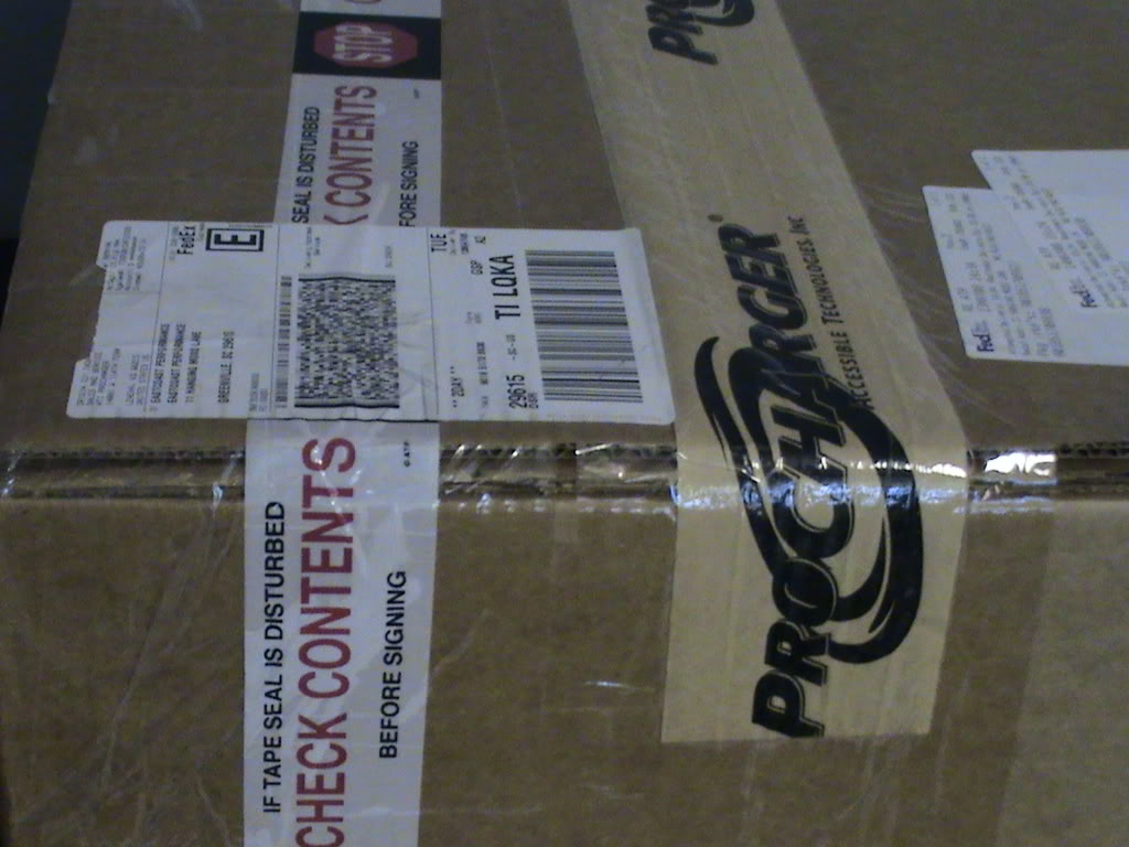
This one is sealed too!
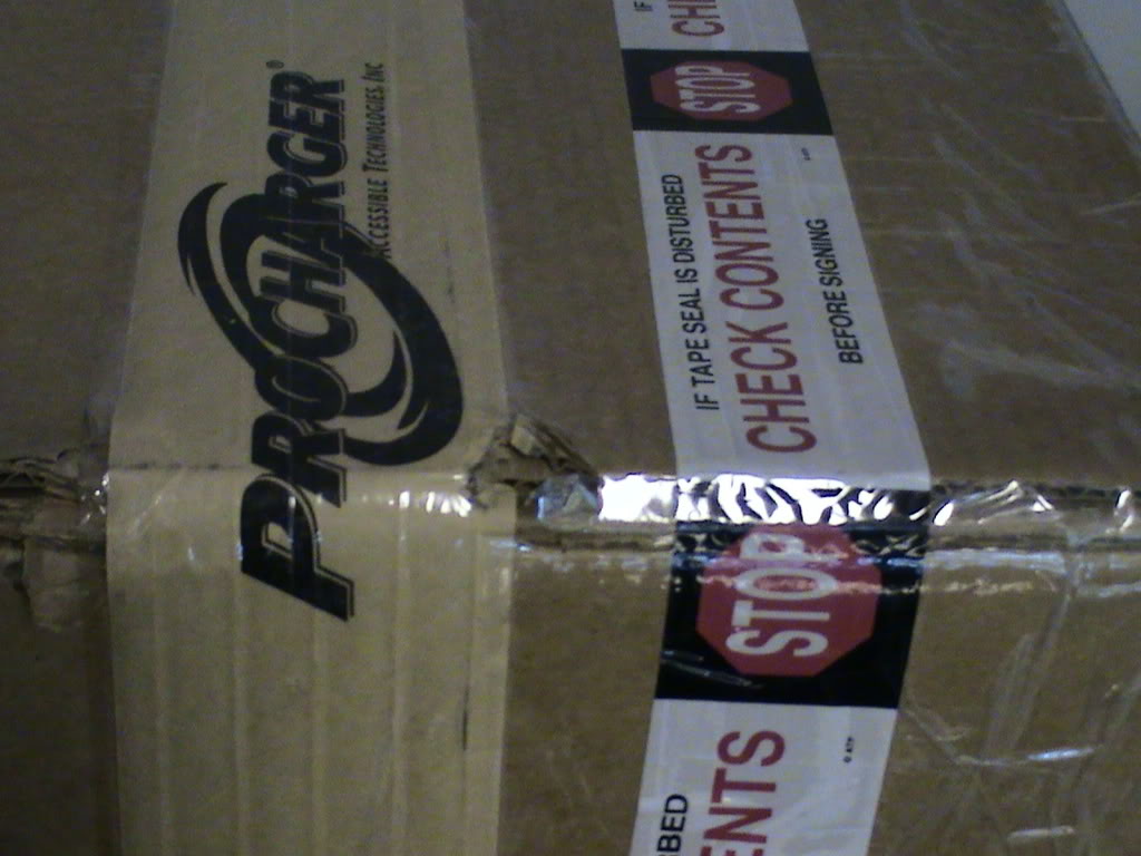
And this looks good...
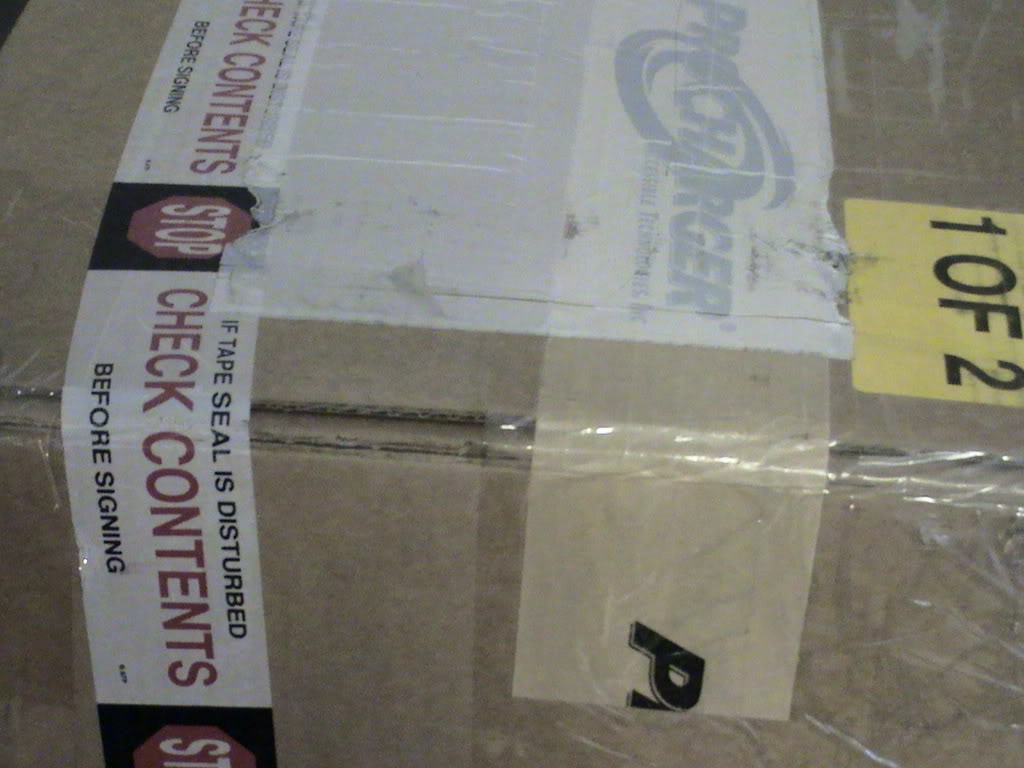
Lets rip them open!
Parts bags...
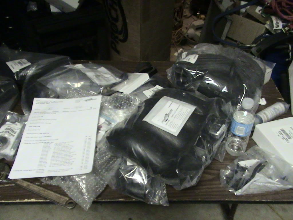
More parts bags...
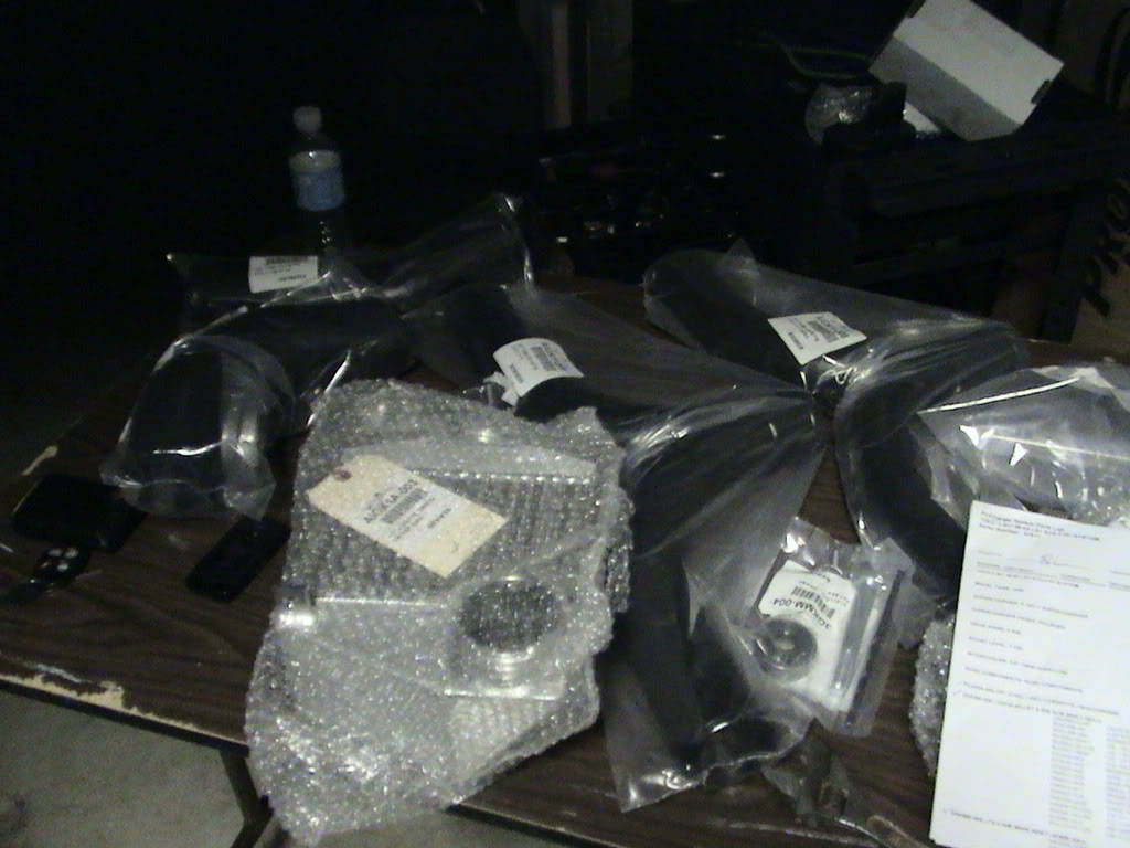
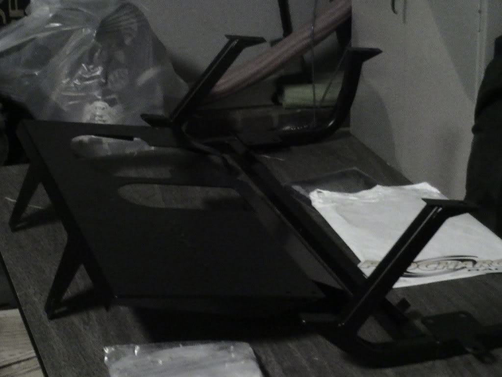
Here is the new radiator carriage, and the top plate
Day 1
Started on Thursday evening. Pulled to car in the garage diagonally to gain the most space. Setup three folding tables to help manage all the parts. I documented the two boxes were still sealed from the factory, then unpacked everything and checked off against the packing list.
This edge looks good...
This one is sealed too!
And this looks good...
Lets rip them open!
Parts bags...
More parts bags...
Here is the new radiator carriage, and the top plate
Last edited by clif; 07-18-2008 at 12:48 PM.


 07-07-2008, 02:37 PM
#5
Melting Slicks
Thread Starter
Member Since: Jul 2007
Location: Simpsonville SC
Posts: 2,939
Likes: 0
Received 4 Likes
on
4 Posts
St. Jude Donor '09-'10
On Friday, I started around 10:00 AM. I decided to pull my X-Pipe, to have a bung welded in for the Wideband O2 sensor (more on this later).
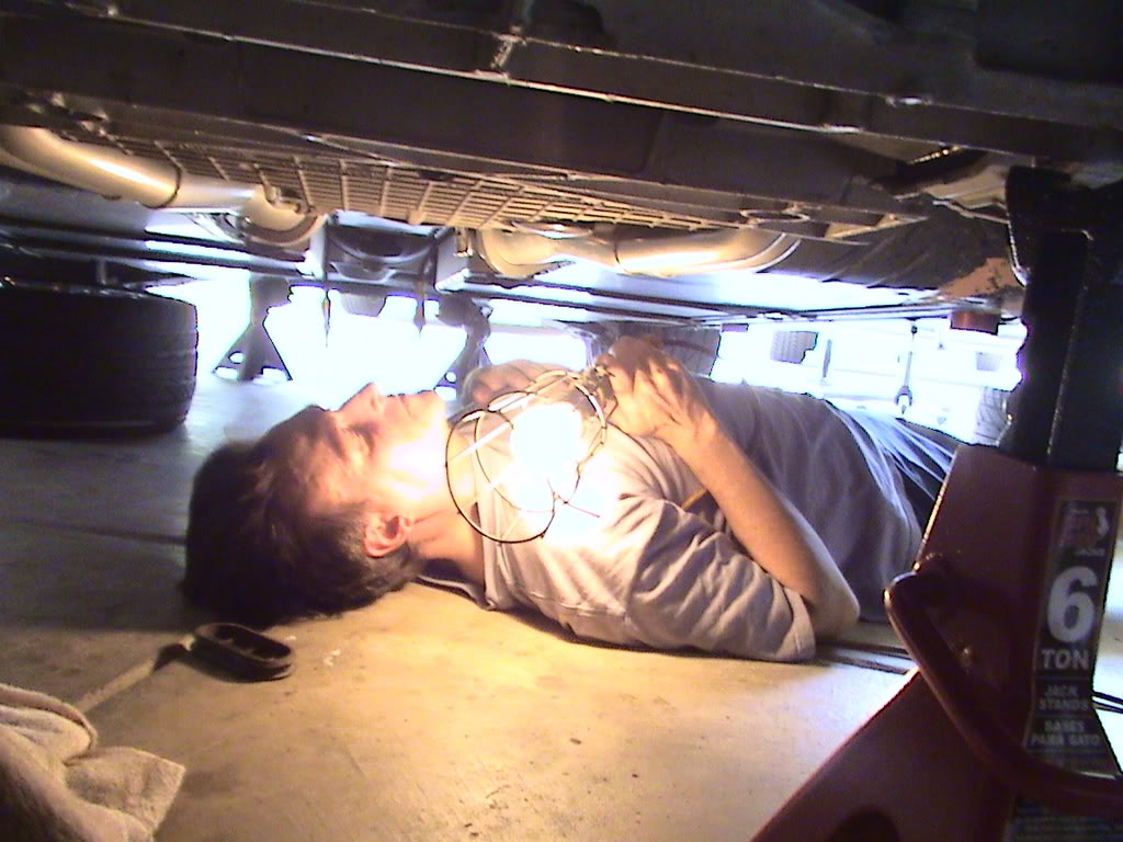
After that was pulled, I began preparing for 'Pinning the Crank'. This step is needed to ensure the extra HP does not spin the harmonic balancer! Many hours went into the preparation for this:
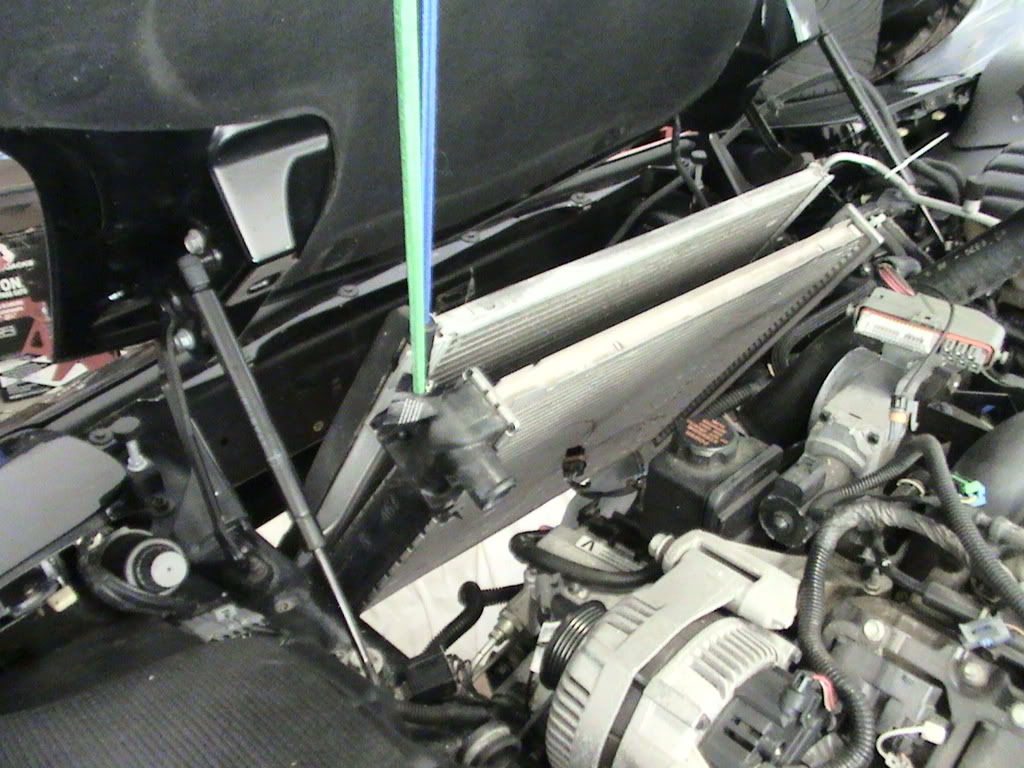
First, the radiator and condensor needed to be raised out of the way:
Up higher!
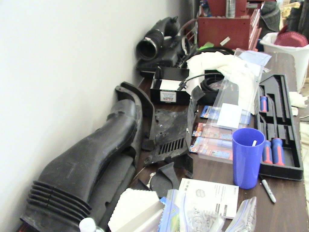
here are the parts pulled off so far:
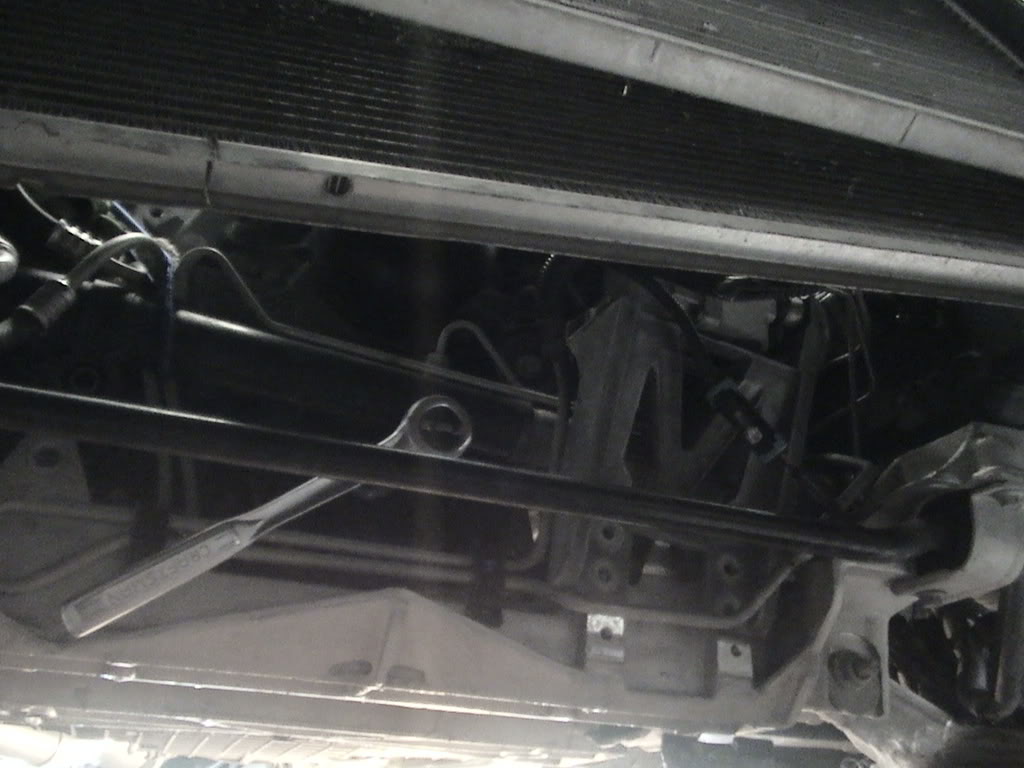
Gotta move the steering rack up and out of the way! I did not disconnect the hydraulic lines; just unbolted the tie-rod ends, and the two mounting bolts, then worked the steering rack up high enough to work on the crank bolt. Here is a rachet on the bolt (just to test if I can access the bolt head)
Next, came the tedious process of removing the crank bolt...
First, I tried a rachet with a pipe... no good. could not keep the crank from turning.
Second, I went and purchased a new preumatic impact wrench. I research and found that a 400-500 ft/lbs impact was not good enough, so I went to Northern Tool and bought a 1000 Ft/Lb impact! For $149.99, I found the ideal tool!
http://www.northerntool.com/webapp/w...4929_200314929
Well, with the recommended 90 PSI onthe compressor, the bolt did not budge. I cranked the pressure up to 100, then 110, then 120 PSI. Finally! it came out! After several hours of fighting and exhaustion, it came out!
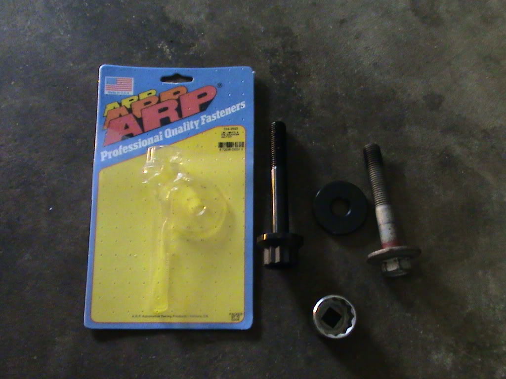
Here is the OLD bolt, next to my new ARP bolt:
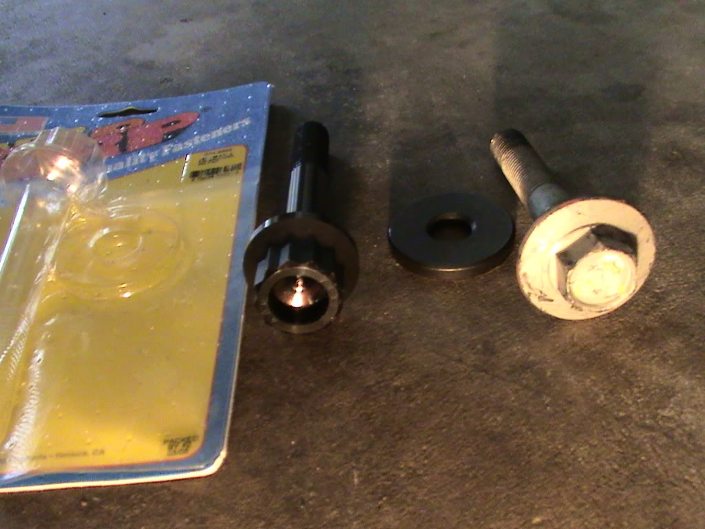
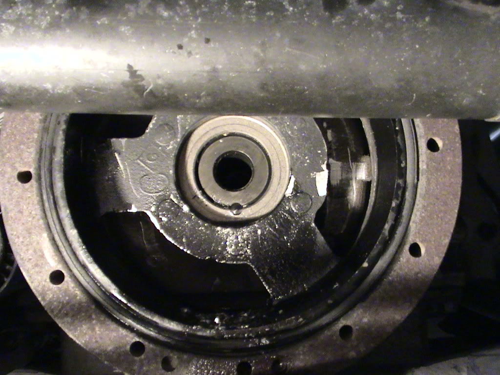
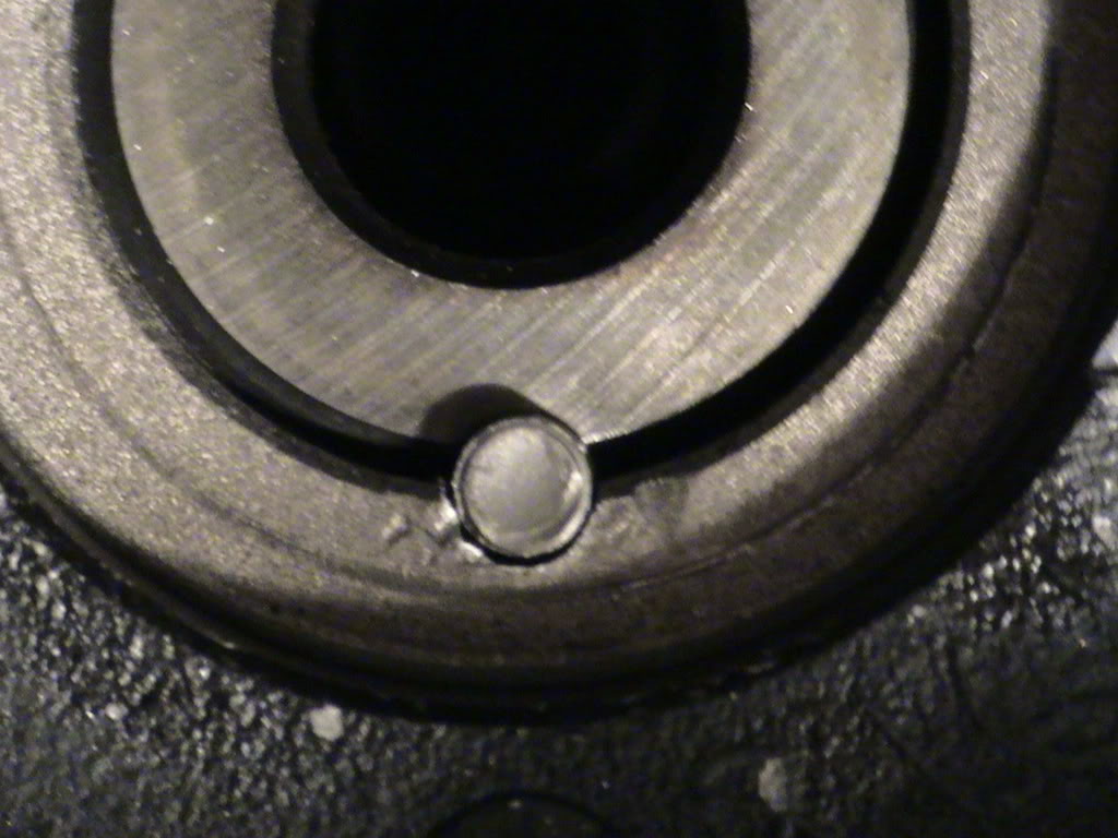
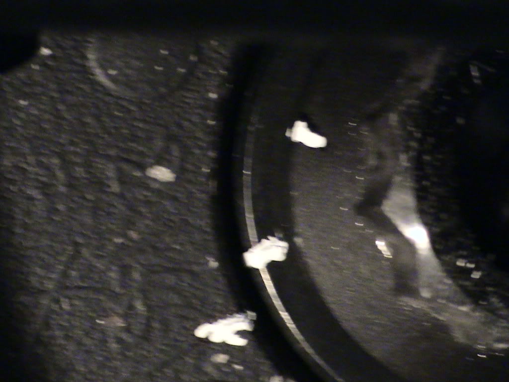
I then unsed the included tool to line up the drill bit, and drilled the hole for the pin. Here it is all pinned up:
Whew, That's all for Day 2.
After that was pulled, I began preparing for 'Pinning the Crank'. This step is needed to ensure the extra HP does not spin the harmonic balancer! Many hours went into the preparation for this:
First, the radiator and condensor needed to be raised out of the way:
Up higher!
here are the parts pulled off so far:
Gotta move the steering rack up and out of the way! I did not disconnect the hydraulic lines; just unbolted the tie-rod ends, and the two mounting bolts, then worked the steering rack up high enough to work on the crank bolt. Here is a rachet on the bolt (just to test if I can access the bolt head)
Next, came the tedious process of removing the crank bolt...
First, I tried a rachet with a pipe... no good. could not keep the crank from turning.
Second, I went and purchased a new preumatic impact wrench. I research and found that a 400-500 ft/lbs impact was not good enough, so I went to Northern Tool and bought a 1000 Ft/Lb impact! For $149.99, I found the ideal tool!
http://www.northerntool.com/webapp/w...4929_200314929
Well, with the recommended 90 PSI onthe compressor, the bolt did not budge. I cranked the pressure up to 100, then 110, then 120 PSI. Finally! it came out! After several hours of fighting and exhaustion, it came out!
Here is the OLD bolt, next to my new ARP bolt:
I then unsed the included tool to line up the drill bit, and drilled the hole for the pin. Here it is all pinned up:
Whew, That's all for Day 2.


 Good luck on the install!
07-07-2008, 02:39 PM
Good luck on the install!
07-07-2008, 02:39 PM
#8
Race Director


Member Since: Apr 2007
Location: Ideals are peaceful...History is violent...St.Charles, MO.
Posts: 17,920
Received 440 Likes
on
228 Posts
2020 Corvette of the Year Finalist (appearance mods)
C5 of Year Winner (appearance mods) 2019
St. Jude Donor '08-'09-'12-'13-'14-'15-'16-'17-'18-'19-'20-'21-'22

Very nice mod

07-07-2008, 02:56 PM
#10
Safety Car

Brings back memories. We installed mine at my brothers house three years ago (A&A procharger kit). I've also helped a firend install his procharger kit on a 1996 vette in my garage about a year and a half ago.
Keep up the good work. It will get frustrating at times but keep at it. The end result is a lot of fun!
Keep up the good work. It will get frustrating at times but keep at it. The end result is a lot of fun!
07-07-2008, 03:28 PM
#11
Melting Slicks
Thread Starter
Member Since: Jul 2007
Location: Simpsonville SC
Posts: 2,939
Likes: 0
Received 4 Likes
on
4 Posts
St. Jude Donor '09-'10
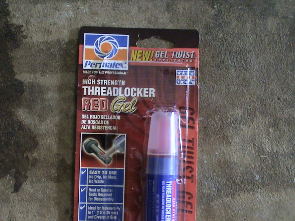
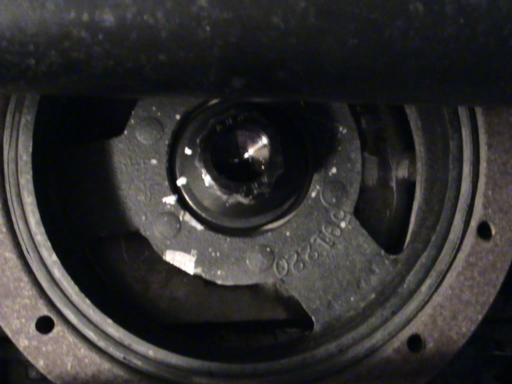
Well, Day 3 was Saturday. I began by installing the new ARP bolt. I coated it with a Loctite clone (Permatex Red)
According to the Procharger Installation manual, I should tighten the bolt to 40 Ft/Lbs + 120 degrees of rotation. For anyone who thinks that is not tight, think again! After I got my bolt torqued to 40 Ft/Lbs, I used a white-out pen to mark the bolt, washer, and pulley. With my new impact wrench at full force, I only was able to get it to turn maybe 60 degrees!
With 1000 Ft-Lbs of force, and the Red loctite, I feel it is sufficiently tight. Anyone think differently?
Anyway, on to mounting the new radiator carriage... sorry, I don't yet have those pics with me. I will post later on in an edit.
Stretching the AC lines and the transmission lines (Yes, I have an A4) was very tedious. The book only said th 'slightly' straighten up the AC line. Slightly was nowhere near what I had to do! I had to REMOVE two 90 degree bends very carefully, and rework a transmission line too!
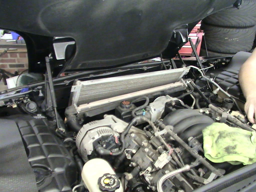
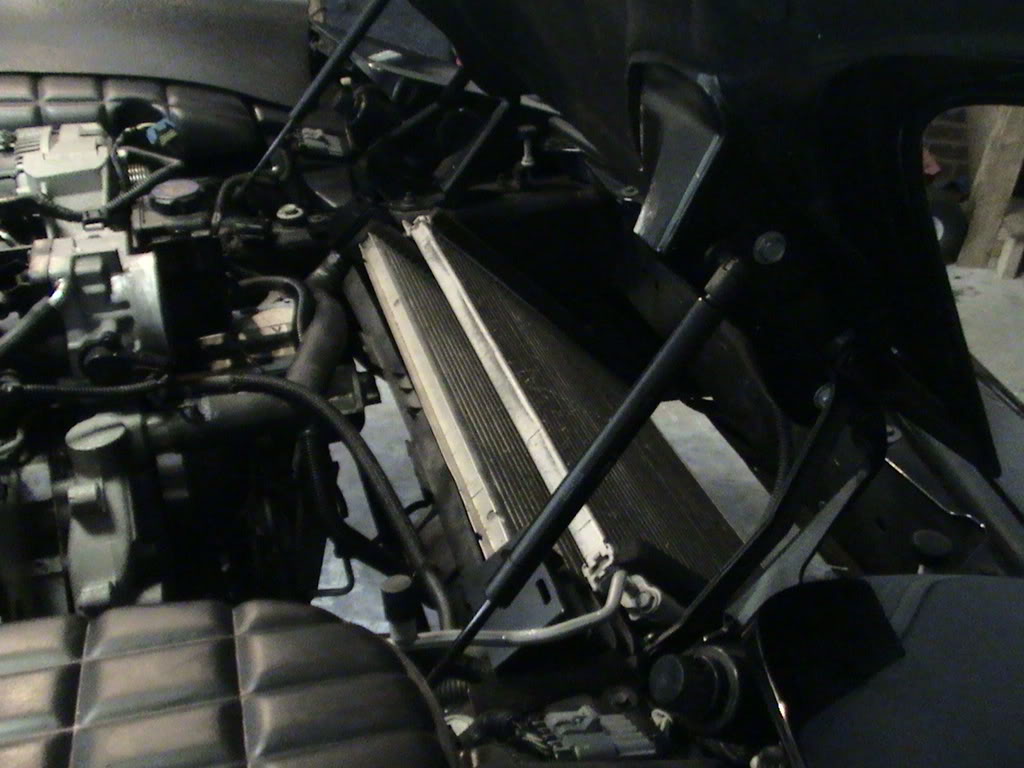
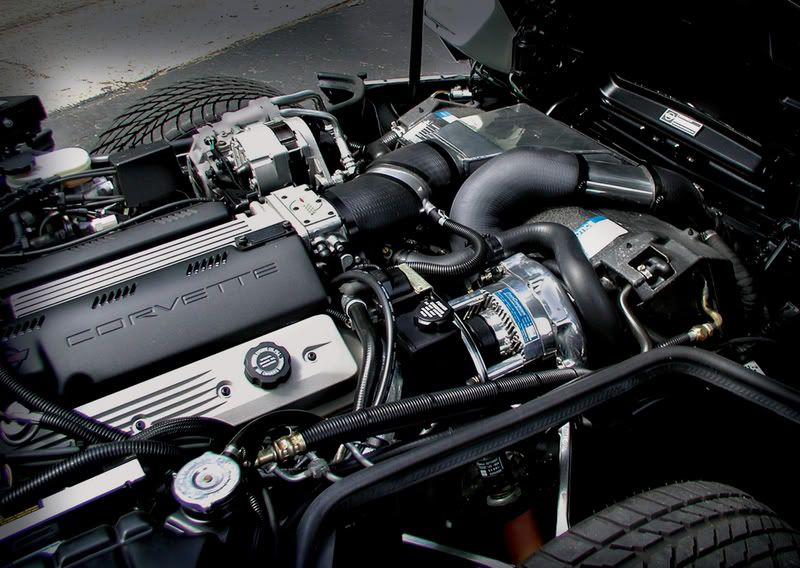
Anyway, the radiator and the condensor are now in their new home. Notice the steep angle of their mount now:
That's it for Day3.
I took Sunday off to thank to Lord for the progress so far. I had to work today, so Day4 starts when I get home!
According to the Procharger Installation manual, I should tighten the bolt to 40 Ft/Lbs + 120 degrees of rotation. For anyone who thinks that is not tight, think again! After I got my bolt torqued to 40 Ft/Lbs, I used a white-out pen to mark the bolt, washer, and pulley. With my new impact wrench at full force, I only was able to get it to turn maybe 60 degrees!
With 1000 Ft-Lbs of force, and the Red loctite, I feel it is sufficiently tight. Anyone think differently?
Anyway, on to mounting the new radiator carriage... sorry, I don't yet have those pics with me. I will post later on in an edit.
Stretching the AC lines and the transmission lines (Yes, I have an A4) was very tedious. The book only said th 'slightly' straighten up the AC line. Slightly was nowhere near what I had to do! I had to REMOVE two 90 degree bends very carefully, and rework a transmission line too!
Anyway, the radiator and the condensor are now in their new home. Notice the steep angle of their mount now:
That's it for Day3.
I took Sunday off to thank to Lord for the progress so far. I had to work today, so Day4 starts when I get home!
Last edited by clif; 07-07-2008 at 03:30 PM.
07-07-2008, 05:24 PM
#13
Le Mans Master

Stretching the AC lines and the transmission lines (Yes, I have an A4) was very tedious. The book only said tt 'slightly' straighten up the AC line. Slightly was nowhere near what I had to do! I had to REMOVE two 90 degree bends very carefully, and rework a transmission line too!
I'm happy to see that Procharger's instructions are just as full of understatements as they were when I installed one of their kits on my '92 Vette back in 1998.
Step 46: Remove engine.
Step 47: Balance on end of your d**k.
Step 48: Reinstall engine.
The following 3 users liked this post by Virtual Geezer:
 good documentation..
07-07-2008, 06:07 PM
good documentation..
07-07-2008, 06:07 PM
#16
Race Director

This is an excellent thread -- will show everyone just how much work installing one of these 'bolt-on' kits is.
I'm happy to see that Procharger's instructions are just as full of understatements as they were when I installed one of their kits on my '92 Vette back in 1998.
Step 46: Remove engine.
Step 47: Balance on end of your d**k.
Step 48: Reinstall engine.
I'm happy to see that Procharger's instructions are just as full of understatements as they were when I installed one of their kits on my '92 Vette back in 1998.
Step 46: Remove engine.
Step 47: Balance on end of your d**k.
Step 48: Reinstall engine.

 07-07-2008, 07:10 PM
#20
Le Mans Master
This is an excellent thread -- will show everyone just how much work installing one of these 'bolt-on' kits is.
I'm happy to see that Procharger's instructions are just as full of understatements as they were when I installed one of their kits on my '92 Vette back in 1998.
Step 46: Remove engine.
Step 47: Balance on end of your d**k.
Step 48: Reinstall engine.
I'm happy to see that Procharger's instructions are just as full of understatements as they were when I installed one of their kits on my '92 Vette back in 1998.
Step 46: Remove engine.
Step 47: Balance on end of your d**k.
Step 48: Reinstall engine.

Great thread by the way!