
C5 Instrument Cluster removal
 02-15-2012, 11:13 AM
#1
Navigator

Thread Starter

Member Since: Dec 2009
Posts: 9
Likes: 0
Received 0 Likes
on
0 Posts
Looking to add the polished rings around the instruments in the cluster.
Anyone know how hard of a job it is to remove and re-install the cluster?
Is this for the professional only? Thanks
Anyone know how hard of a job it is to remove and re-install the cluster?
Is this for the professional only? Thanks
 02-15-2012, 11:37 AM
#2
Le Mans Master

I did mine last summer and went a little further as I also added the white face gauges. I took my time and followed the instructions step by step and from start to finish it took about 2 hours. So to answer your question, No it should not require a professional shop to do the work as long as you have the needed tools and a little mechanical ability.
02-15-2012, 11:41 AM
#4
Navigator
Thread Starter
Member Since: Dec 2009
Posts: 9
Likes: 0
Received 0 Likes
on
0 Posts
Thanks,
 02-15-2012, 11:45 AM
#5
Race Director


Just becareful and do not yank on anything. Also helps to lower steering column and tilt down.
Basically you pull off knee bolster, (2) 13MM nuts on steering column brace, Tilt Wheel down, remove T15 screws from upper bezel and then on the two sides. Eaze out gauges and disconnect ribbon harnesses.
Basically you pull off knee bolster, (2) 13MM nuts on steering column brace, Tilt Wheel down, remove T15 screws from upper bezel and then on the two sides. Eaze out gauges and disconnect ribbon harnesses.
02-15-2012, 11:48 AM
#6
Tech Contributor
Member Since: Aug 1999
Location: Should this thoughtful, valuable contribution meet with no acknowledgement or 'thanks' this post----
Posts: 16,382
Received 399 Likes
on
257 Posts

I did mine years ago...it is not that simple....find a good writeup and go from that. when you glue the rings make sure you use a very small amount of adhesive so it doesn't squeeze out the edges. you have to drop the steering column and that is the nervous part...lots of hardware has to be removed to get to where you can install the rings...make sure your back is in good shape before taking this task on...
02-15-2012, 12:53 PM
#7
Le Mans Master
As I mentioned in my first post just follow the instruction. here is a link to the instructions.
http://www.vetteessentials.com/instr...zel_howto.html
http://www.vetteessentials.com/instr...zel_howto.html
02-15-2012, 03:51 PM
#8
Burning Brakes

Member Since: Jul 1999
Location: The Usual Suspects Yorba Linda Chapter
Posts: 1,018
Likes: 0
Received 0 Likes
on
0 Posts
Take your time and you should be fine. The scariest part for me was pulling off the connector for the HUD. Just work it for a while. If you pull to hard and rip the connector....you won't be happy.
02-15-2012, 06:29 PM
#9
Le Mans Master
Member Since: Feb 2003
Location: Memphis Tennessee
Posts: 6,670
Likes: 0
Received 135 Likes
on
84 Posts
It is more of a process than you would think. Go to www.vetteessentials.com for the instructions, then youcanmake your decision.
Go for it.
 02-15-2012, 09:13 PM
#11
Le Mans Master

Done two of them...my '99, and the wife's '01...both with excellent results. As mentioned, take your time and you will be pleased.
Wife's '01
My '99 was pretty much the same, red instead of white.
Wife's '01
My '99 was pretty much the same, red instead of white.
02-15-2012, 09:16 PM
#12
Administrator


Member Since: Mar 2001
Location: In a parallel universe. Currently own 2014 Stingray Coupe.
Posts: 342,677
Received 19,219 Likes
on
13,929 Posts
C7 of the Year - Modified Finalist 2021
MO Events Coordinator
St. Jude Co-Organizer
St. Jude Donor '03-'04-'05-'06-'07-'08-'09-'10-'11-'12-'13-'14-'15-'16-'17-'18-'19-
'20-'21-'22-'23-'24
NCM Sinkhole Donor
CI 5, 8 & 11 Veteran

It is more of a process than you would think. Go to www.vetteessentials.com for the instructions, then youcanmake your decision.
02-15-2012, 10:52 PM
#13
Melting Slicks

To the OP... if you're reasonably mechanical, taking out the cluster is not that bad. However, be extremely careful when installing the guage bezels. I ended up screwing up mine with an outcome of 7 out of 10 at best. The glue part is difficult because it needs to remain on the reverse side of the bezels and not get transferred to your fingers or anywhere on the cluster. This is the part of the job that is definitely for the true craftsman.
02-16-2012, 12:14 AM
#14

Its not a tough job. I didn't need any special tools to pull the cluster out. Just time consuming your 1st go around. I ended having to go in there at least 6 times due to bezels falling off and connectors not properly seating.
Once you get the cluster out, you can separate the black piece where the bezel will be glued to from the entire instrument cluster. It makes the job so much easier to glue as you get greater control to move around to glue because you have access from the back. Less chance of getting glue everywhere.
FYI, I ended up using JB quik to glue the bezels on. (That is a permanent as you can get it, I hear super glue can degrade overtime and lose its effectiveness) I used the flimsy tape that came with mine. Don't use that.
02-16-2012, 02:20 AM
#15
Tech Contributor
Member Since: Dec 2003
Location: Horncastle Lincolnshire, England
Posts: 19,384
Likes: 0
Received 79 Likes
on
61 Posts
2023 C5 of the Year Finalist - Unmodified

PM me if you want a copy with pictures
Remove Console using Vette Essentials instructions:
http://www.vetteessentials.com/instr...brake_h_b.html
Instrument Panel Cluster (IPC) Replacement
Removal Procedure
Notice
Whenever the Instrument Panel Cluster (IPC) is removed from the vehicle, DO NOT set the IPC on its face for more than 15 minutes or damage to the fluid filled air core gages may result.
Caution
Before servicing any electrical component, the ignition key must be in the OFF or LOCK position and all electrical loads must be OFF, unless instructed otherwise in these procedures. If a tool or equipment could easily come in contact with a live exposed electrical terminal, also disconnect the negative battery cable. Failure to follow these precautions may cause personal injury and/or damage to the vehicle or its components.
1. Disconnect the negative battery cable.
2. Remove the I/P upper trim pad. Refer to Trim Pad Replacement - Instrument Panel (I/P) Upper .
3. Carefully lift the head-up display (HUD) electrical harness from between the instrument panel cluster (IPC) and the HUD, if equipped.
4. Disconnect the HUD electrical connector from the IPC, if equipped.
5. Remove the retaining screws that secure the IPC to the steering column bracket.
6. Raise the rear of the IPC slightly to release the locator tab, then lift the IPC to access the electrical connector.
7. Disconnect the IPC electrical connector.
8. Remove the IPC.
Installation Procedure
1. Connect the IPC electrical connector.
2. Position the IPC to the steering column bracket.
3. Verify that the IPC retaining tab (1) is positioned correctly to the steering column bracket (2).
Notice
Use the correct fastener in the correct location. Replacement fasteners must be the correct part number for that application. Fasteners requiring replacement or fasteners requiring the use of thread locking compound or sealant are identified in the service procedure. Do not use paints, lubricants, or corrosion inhibitors on fasteners or fastener joint surfaces unless specified. These coatings affect fastener torque and joint clamping force and may damage the fastener. Use the correct tightening sequence and specifications when installing fasteners in order to avoid damage to parts and systems.
4. Install the retaining screws that secure the IPC to the steering column bracket.
Tighten
Tighten the retaining screws to 3 N�m (27 lb in).
5. Connect the HUD electrical connector to the IPC, if equipped.
6. Carefully tuck the HUD electrical harness (1) down between the IPC and the HUD as shown.
7. Install the I/P upper trim pad. Refer to Trim Pad Replacement - Instrument Panel (I/P) Upper .
8. Connect the negative battery cable.
Tighten
Tighten the bolt to 15 N�m (11 lb ft).
9. Program the transmitters. Refer to Transmitter Programming in Keyless Entry.
10. Synchronize the transmitters. Refer to Transmitter Synchronization in Keyless Entry.
Trim Pad Replacement - Instrument Panel (I/P) Upper
Removal Procedure
1. Remove the console. Refer to Console Replacement .
2. Remove the IP accessory trim plate. Refer to Trim Plate Replacement - Instrument Panel (I/P) Accessory .
3. Remove the driver knee bolster trim panel. Refer to Trim Panel Replacement - Knee Bolster .
4. Remove the instrument panel compartment. Refer to Compartment Replacement - Instrument Panel (I/P) .
5. Remove the windshield defroster grille. Refer to Defroster Grille Replacement .
6. Insert the DRL and sunload sensors, if equipped, into the nearest openings in the windshield defroster duct.
Moving the sensors into the defroster duct provides additional clearance to remove the trim pad.
7. Remove the windshield side garnish moldings. Refer to Windshield Side Garnish Molding Replacement in Interior Trim.
8. Remove the screws retaining the upper trim pad to the defroster duct.
9. Remove the screws retaining the upper trim pad to the LH and RH hinge pillars.
10. Remove the screws retaining the IP cluster bezel to the upper trim pad.
11. Remove the screws retaining the upper trim pad to the driver knee bolster outer bracket and the center support bracket.
12. Remove the screw retaining the upper trim pad to the passenger SIR bracket.
13. Tilt the steering wheel to the lowest position.
14. Lift the rearward edge of the upper trim pad approximately 5 cm (2 in) to provide clearance for the air distribution duct located on the underside of the trim pad.
15. SLOWLY pull the upper trim pad away from the windshield while guiding the tabs on the LH and RH side of the trim pad past the hinge pillars.
16. Disconnect the hazard warning switch electrical connector.
17. Remove the upper trim pad from the vehicle.
Installation Procedure
1. Connect the hazard warning switch electrical connector.
2. Install the IP upper trim pad into position.
A. Tilt the forward edge of the trim pad down slightly.
B. SLOWLY begin to move the trim pad into position while guiding the tabs on the LH and RH side of the trim pad past the hinge pillars.
C. Locate the trim pad by guiding the alignment notch on the underside of the pad onto the alignment pin on the dash panel.
D. Lower the rearward edge of the pad into place.
Remove the DRL and sunload sensors, if equipped, from the openings in the windshield defroster duct and position above the trim pad.
Notice
Use the correct fastener in the correct location. Replacement fasteners must be the correct part number for that application. Fasteners requiring replacement or fasteners requiring the use of thread locking compound or sealant are identified in the service procedure. Do not use paints, lubricants, or corrosion inhibitors on fasteners or fastener joint surfaces unless specified. These coatings affect fastener torque and joint clamping force and may damage the fastener. Use the correct tightening sequence and specifications when installing fasteners in order to avoid damage to parts and systems.
Install the screws retaining the upper trim pad to the windshield defroster duct.
Tighten
Tighten the IP upper trim pad to windshield defroster duct screws to 1.9 N�m (17 lb in).
Install the screws retaining the upper trim pad to the LH and RH hinge pillars.
Tighten
Tighten the IP upper trim pad to LH and RH hinge pillar screws to 2.5 N�m (22 lb in).
Install the screws retaining the upper trim pad to the driver knee bolster outer bracket, the center support bracket and the passenger SIR bracket.
Tighten
o Tighten the IP upper trim pad to driver knee bolster outer bracket screw to 1.9 N�m (17 lb in).
o Tighten the IP upper trim pad to IP center support bracket screws to 1.9 N�m (17 lb in).
o Tighten the IP upper trim pad to passenger SIR bracket screw to 1.9 N�m (17 lb in).
Install the screws retaining the IP cluster bezel to the upper trim pad.
Tighten
Tighten the IP cluster bezel to IP upper trim pad screws to 1.3 N�m (12 lb in).
Install the windshield side garnish moldings. Refer to Windshield Side Garnish Molding Replacement in Interior Trim.
Install the windshield defroster grille. Refer to Defroster Grille Replacement .
Install the instrument panel compartment. Refer to Compartment Replacement - Instrument Panel (I/P) .
Install the driver knee bolster trim panel. Refer to Trim Panel Replacement - Knee Bolster .
Install the IP accessory trim plate. Refer to Trim Plate Replacement - Instrument Panel (I/P) Accessory .
Install the console. Refer to Console Replacement .
 02-16-2012, 06:41 PM
#17
Tech Contributor
Member Since: Aug 1999
Location: Should this thoughtful, valuable contribution meet with no acknowledgement or 'thanks' this post----
Posts: 16,382
Received 399 Likes
on
257 Posts
DeeGee...are you trying to scare him away???? Great writeup!
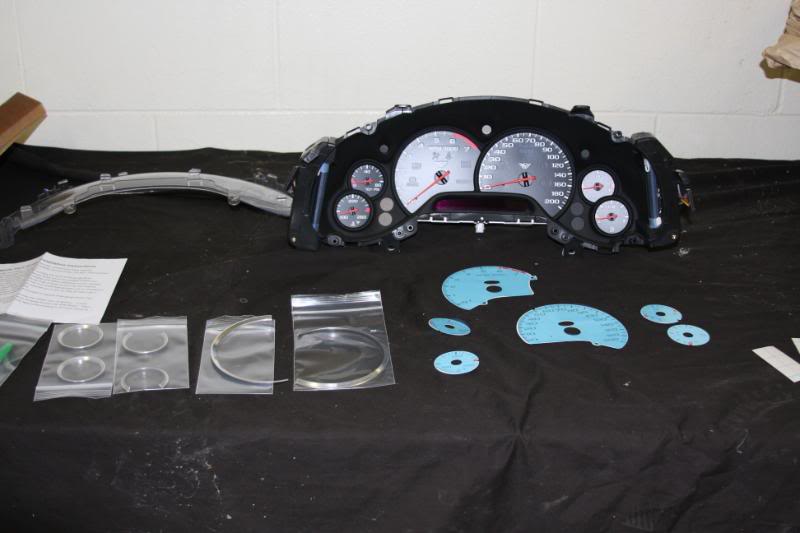
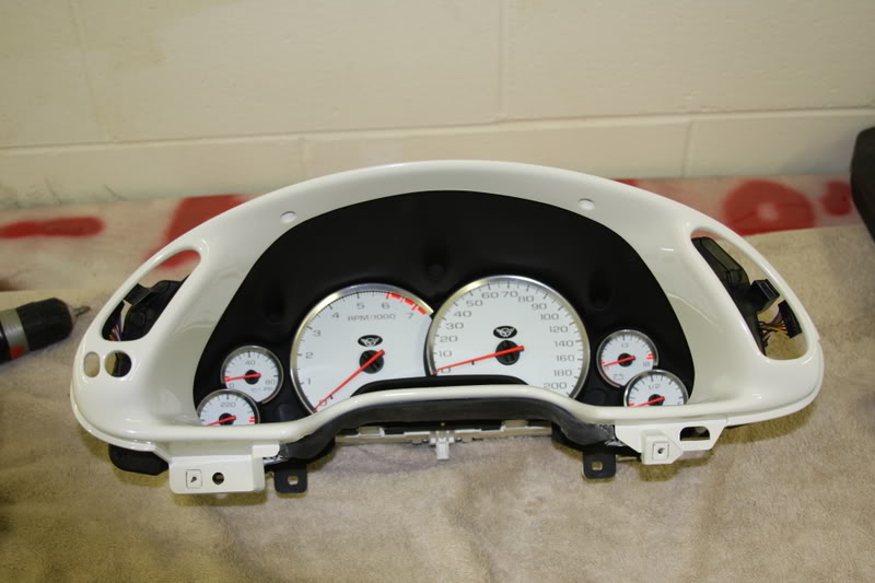
Ok, here is some more info i forgot to mention earlier. Once out of the car take the cluster indoors and work on the kitchen table or a clean workbench. This is the time to have a clear head, and maybe a couple diet cokes handy. The disassembly of the cluster is a little cumbersome and delicate at the same time....keep everything organized and you will do fine...take pictures as you go so you can remember the steps in reverse...don't get fingerprints on any surface where they will be seen, like inside the clear lens. This is the time to perform any other mods such as painting the bezel, or the background of the speedo. Here are some pics to show you what to expect and what you can do at this point:
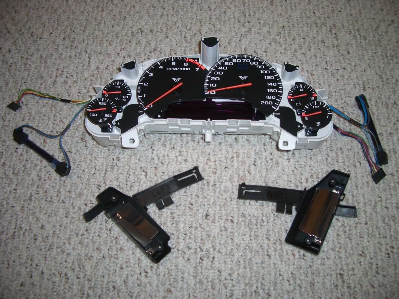
The electronics once removed...those are UV lights on the sides...careful with those.
the bezel.....
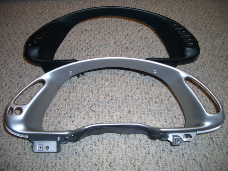
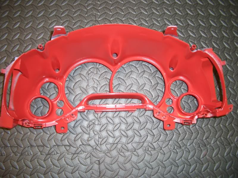
paint work....silver to match rings...torch red to match body color
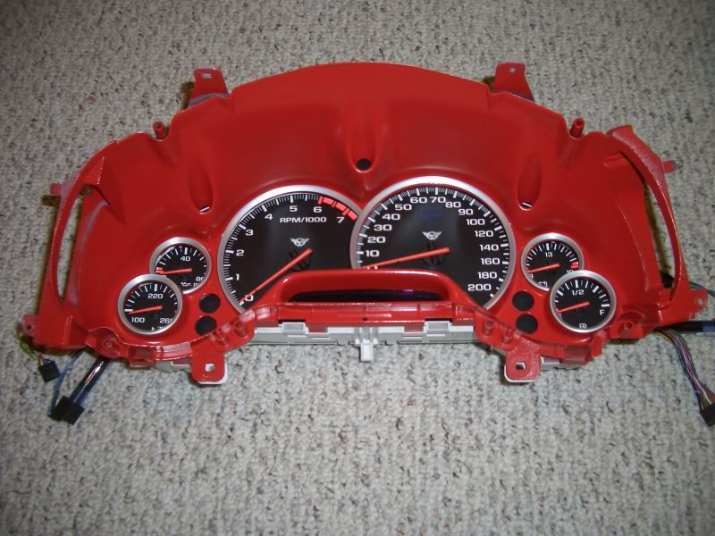
coming together....
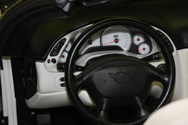
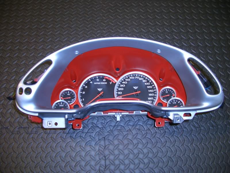
final product...caution...omit clearcoat to prevent glare!
you can do this over a few days if you like...if I am not mistaken, the car will start and is still driveable without the cluster...it's been so long I can't exactly remember...but I have driven my car with a lot of stuff missing from the dash at one time or another, and I think this was one of them. Best of luck and show us your results!
Great writeup!Ok, here is some more info i forgot to mention earlier. Once out of the car take the cluster indoors and work on the kitchen table or a clean workbench. This is the time to have a clear head, and maybe a couple diet cokes handy.
The disassembly of the cluster is a little cumbersome and delicate at the same time....keep everything organized and you will do fine...take pictures as you go so you can remember the steps in reverse...don't get fingerprints on any surface where they will be seen, like inside the clear lens. This is the time to perform any other mods such as painting the bezel, or the background of the speedo. Here are some pics to show you what to expect and what you can do at this point:The electronics once removed...those are UV lights on the sides...careful with those.
the bezel.....
paint work....silver to match rings...torch red to match body color
coming together....
final product...caution...omit clearcoat to prevent glare!
you can do this over a few days if you like...if I am not mistaken, the car will start and is still driveable without the cluster...it's been so long I can't exactly remember...but I have driven my car with a lot of stuff missing from the dash at one time or another, and I think this was one of them. Best of luck and show us your results!
Last edited by $$$frumnuttin'; 02-16-2012 at 06:50 PM.
The following 2 users liked this post by $$$frumnuttin':
Keev1414 (06-14-2021),
oh1c5Pewter (12-27-2020)
02-16-2012, 09:06 PM
#18
Racer
Member Since: Jan 2011
Location: Canon City Colorado
Posts: 301
Likes: 0
Received 0 Likes
on
0 Posts
As I mentioned in my first post just follow the instruction. here is a link to the instructions.
http://www.vetteessentials.com/instr...zel_howto.html
http://www.vetteessentials.com/instr...zel_howto.html
02-16-2012, 09:29 PM
#19
Le Mans Master

Remove center console.
Remove radio / AC bezel.
Remove knee bolster.
Remove bolt holding up steering wheel / column.
Remove torx sscrews holding gauge cluster, pull cluster forward and unplug.
DONE !


