
iPod/AUX input into factory radio write up for $3
 03-18-2013, 01:55 AM
#1
Pro

Thread Starter

I can't take credit for this, but i haven't seen much on this forum about this so here's a little write up on how I did mine...
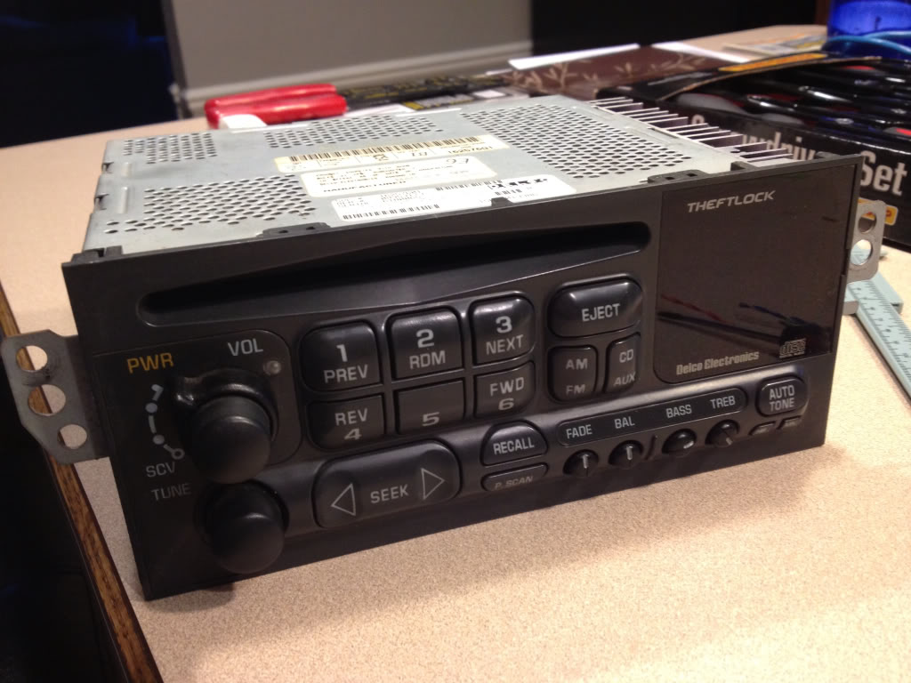
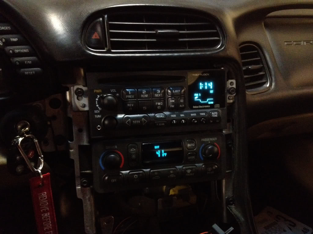
This is what we're starting with....
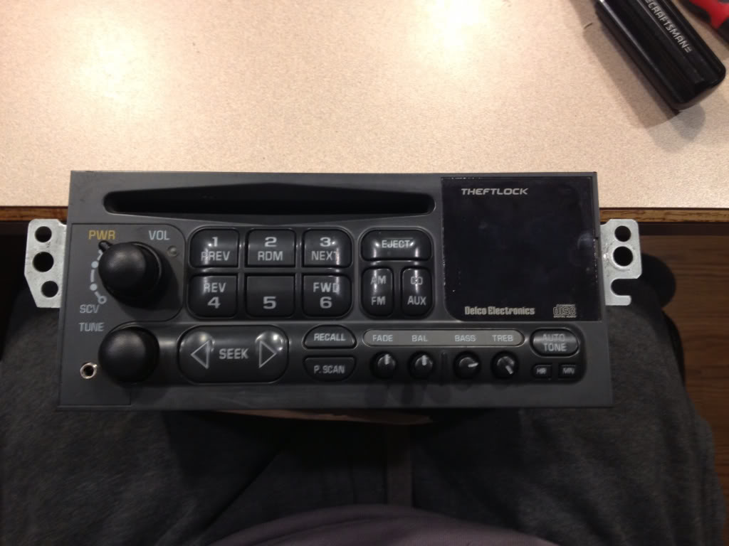
And here's what we're going for...
Again this only cost about $3 dollars and takes a mild bit of mechanical inclination so I wouldn't recommend attempting this if your not even comfortable removing your head unit yourself. If you are, then by all means your capable of getting the job done. This was the first time I've soldered anything since my young engineers class in the 8th grade but its fairly easy work. So even if you've never touched a soldering iron before you can still do this!
Step one.....
Go to RadioShack and pick up this little guy...
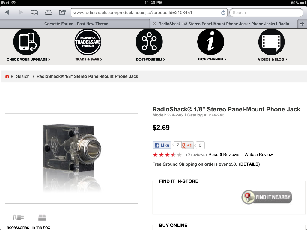
If you don't have a soldering iron, then go ahead and pick one up at RadioShack also, along with a spool of thin soldering wire. I bought the iron with a switch to change the iron from 15watt to 30 watt but found I used it on 30watt setting. You will also need a rotary tool if you dont already have one. I picked mine up at harbor freight for $8 with a coupon and it worked great!
Step two.....
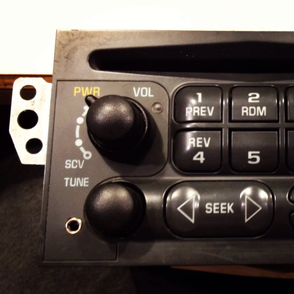
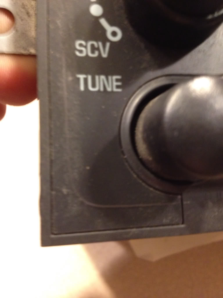
Mark the outline of the radio bezel in the lower left corner of the faceplate of the head unit BEFORE removing anything from the car.... This is after I took it out but here is the mark you need to make with a pencil...
Step three...
If you have a convertible like mine you must remove the waterfall first....next, for all models, remove the center glove box and the center console/radio bezel. You can find a write up on how to do this in the tech forum, or over at vetteessentials.com. Next remove the head unit. PS MAKE SURE YOU KNOW YOUR UNLOCK CODE IF YOUR ANTITHEFT IS ACTIVE ON YOUR HEADUNIT as you will need to unlock it once you reinstall it when your finished. Take out the cd if there's one in it now.
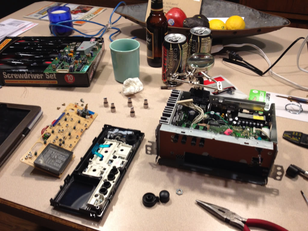
Go ahead and remove your headunit from the car and take it somewhere clean where you won't lose any parts, is well lit, and has an outlet. Since my fianc� doesn't mind me bringing my "projects" in the house, I chose my kitchen island.
Step four...
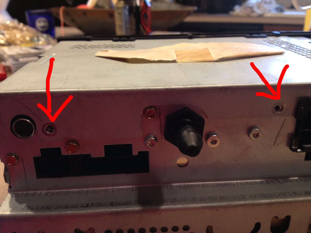
Go ahead and plug in your soldering iron and let it warm up while you start disassembling the head unit. Turn it upside down on your work area and remove these three screws...
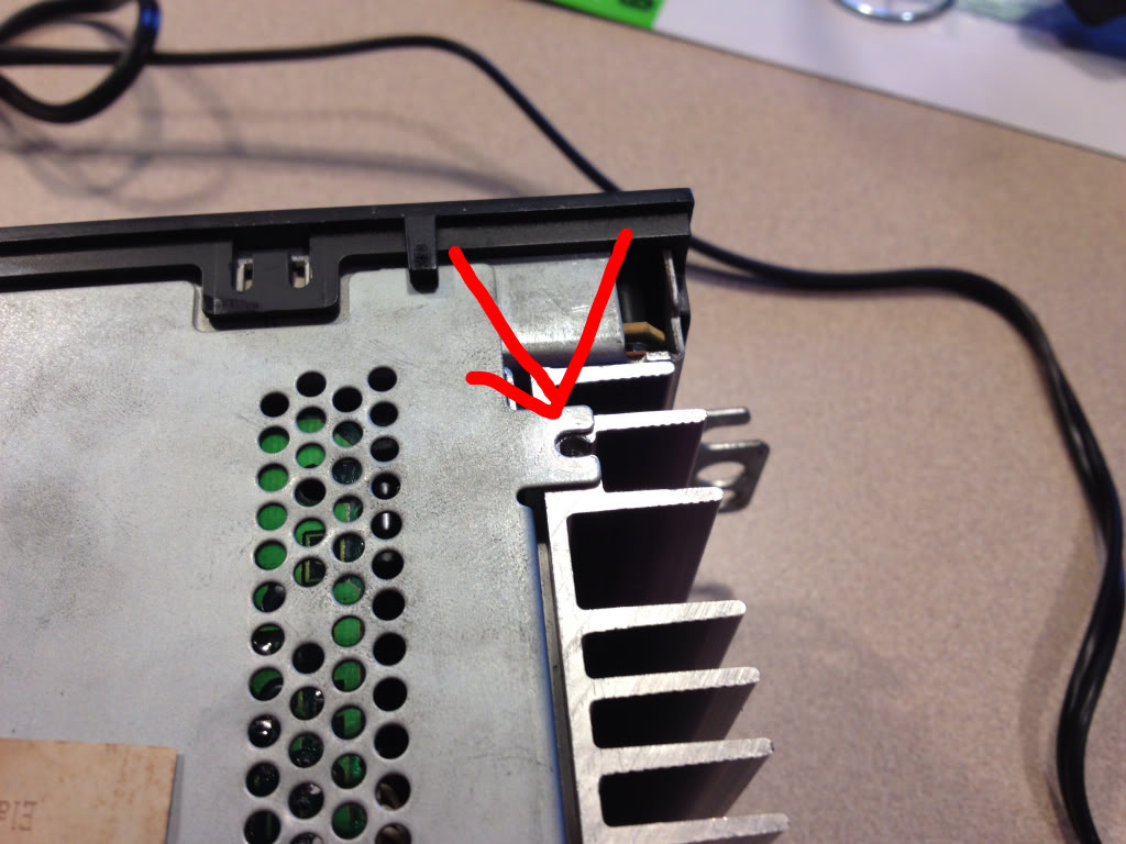
Once the screws are out, pop off the metal lid.... You'll find this underneath...
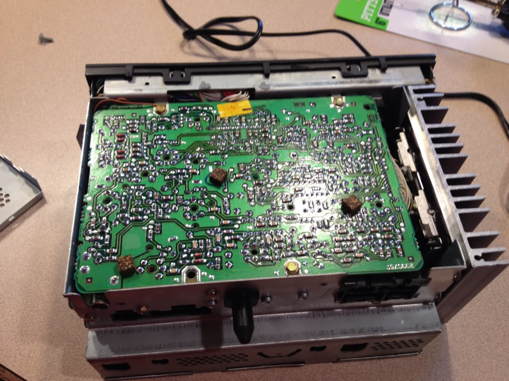
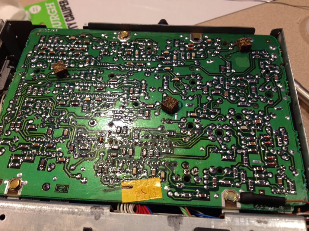
Go ahead and remove all of the remaining gold screws holding this circuit board down.... I think there were 3 on the board itself, then 3 or 4 more through the case on the sides. Underneath you'll find something similar to this. PS this picture is AFTER I had already unplugged a couple things and added a couple wires.... Ignore them for now.
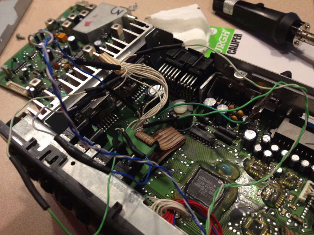
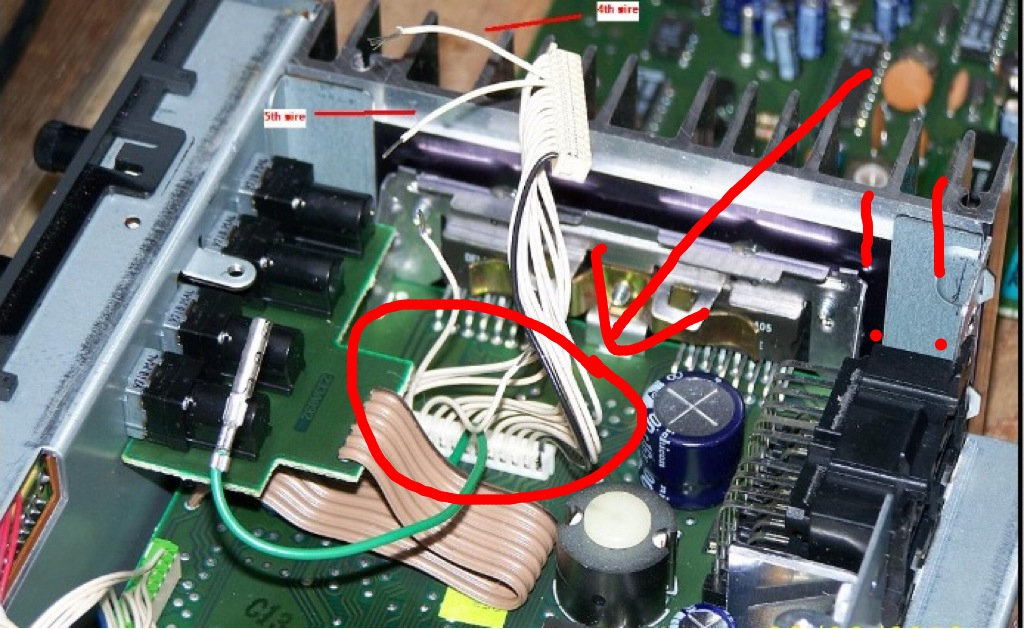
THIS IS VERY IMPORTANT!!!! My car is a 98 and the Head unit is slightly different from some of the newer ones!!! You need to determine which style you have!!! The easiest way I think is to look at where this cable is on the circuit board.... My 98 is located here....
Newer cars it is located here...
It is very important to identify which style you have as it depends which wires we will cut later! I will refer to them as older style and newer style.
Unhook the green cable and the white row of cables connector circled above from the top circuit board you just removed and set it aside somewhere safe for now.
Step five....
Now you need to remove the face plate and the wires attaching it. It's a little tricky to release all the plastic tabs holding it to the case... Just be patient. Also pull the two ***** off and set them aside. I think once you remove the volume **** you will need to unscrew a little nut to separate it from the face. Put it somewhere safe.
Next remove the tiny little screws holding on the circuit board to the face... I didn't have a socket small enough so I grabbed each with a set of needle nose pliers and very CAREULLY unscrewed them. You don't wanna scratch the circuit board!
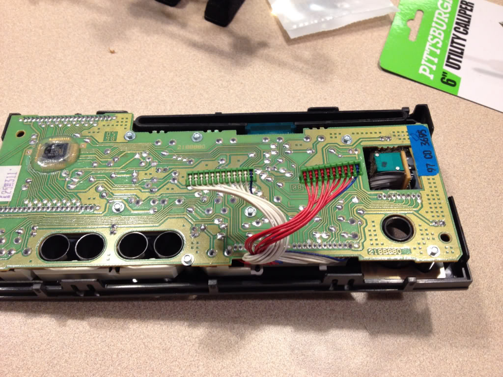
Here's what you should have now....
Now remove the plastic piece and the metal pieces circled below.... This again is a little tricky just be mindful of the little plastic clips.
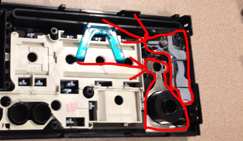
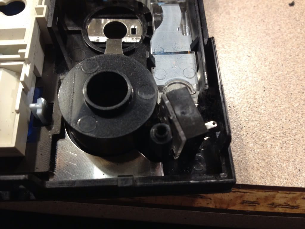
Once removed.... You have this....
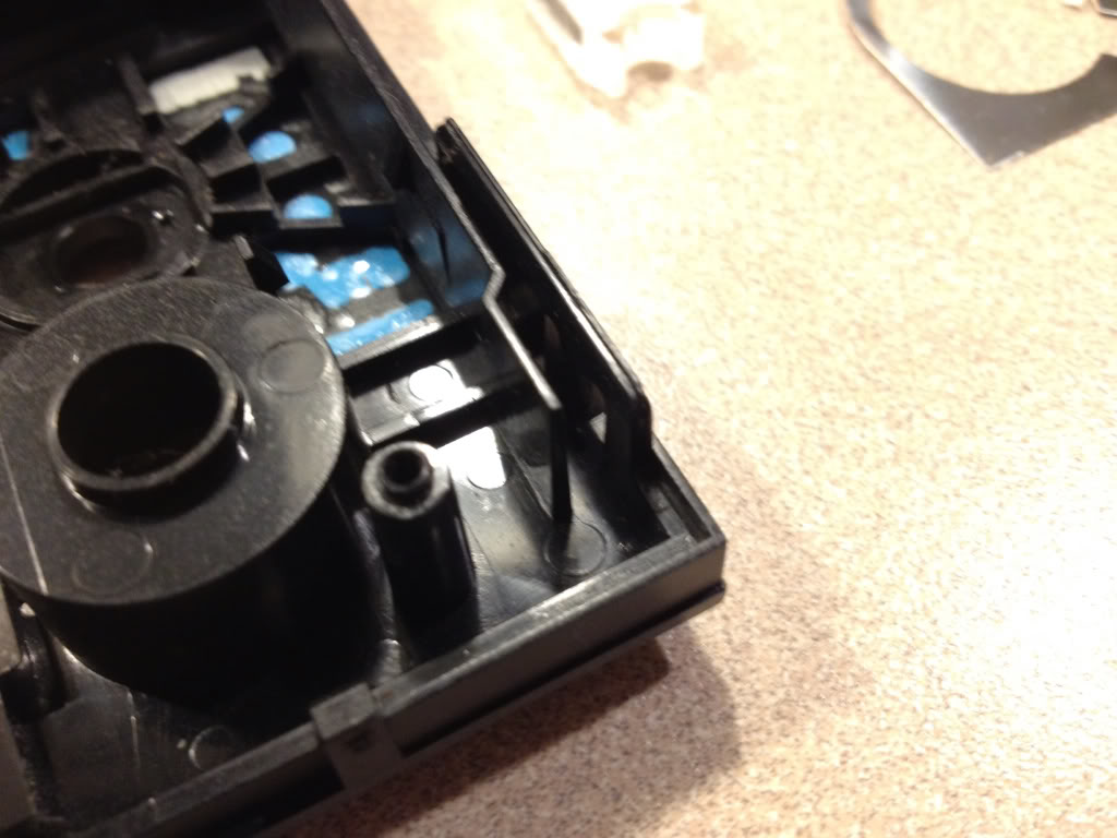
That little plastic tab over on the right will be in the way of the jack..... So get out your rotary tool and cut it out to end up with this...
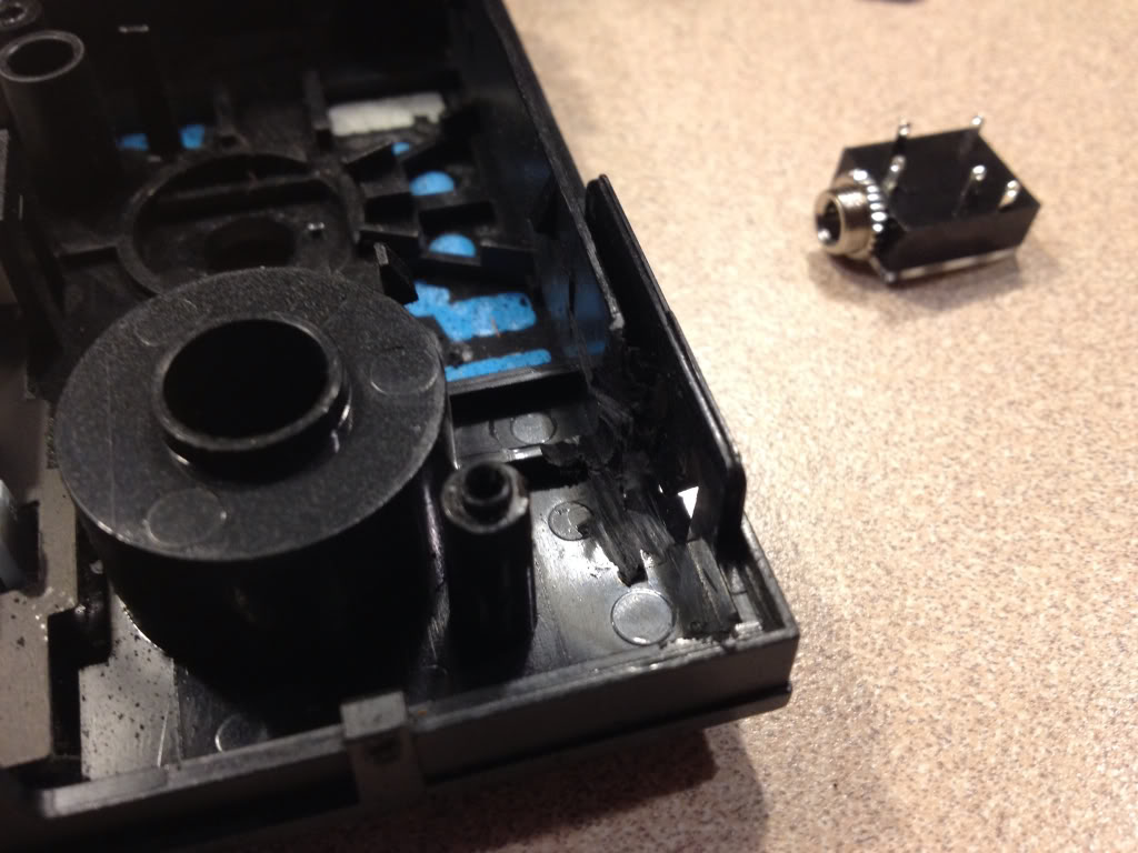
Now you will need to trim the corner off that little metal piece where you removed the plastic tab. Just cut off the corner. Reinstall the plastic and metal pieces.... Now test fit your jack...
If it fits then your good to move on...if not trim a little more with rotary tool. Next mark where you need to drill your hole.... Take some white out or anything else that will transfer and dab it on the metal part of the jack then retest fit... It should transfer to where you need to drill the hole... Not sure what size hole, but it should poke through perfectly flush from the front if you remove the little nut on the new jack.... You won't need it. Make sure before drilling your hole that you are inside your pencil marks from the bezel.
If all is well, move on...
Step six....
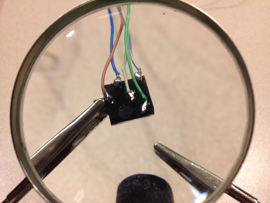
Now we get to solder! I used whats called cat5 cable. It's what you use to hook up your modem to your computer or router. Strip the outer layer and you will find small braided wires that are perfect for this job. I had an extra cable around the house, but they are cheap anywhere just cut off the plugs on the ends. I used the blue solid and blue striped as well as green solid and striped.... Then I separated the brown and used the solid brown as my ground.
My hands shake like a Parkinson's patient so I had a couple beers at this point and it steadied my hand a little ; )
Here is what you need to solder on your jack...
Here's a diagram
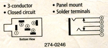
1 is grounded to case
2 goes to "plugged in" end of cut wire #4 (or #1)
3 goes to "unplugged" end of cut wire #4 (or #1)
4 goes to "unplugged end of cut wire #5 (or #3)
5 goes to " plugged in" end of cut wire #5 (or #3)
This is why it is VERY important to determine which style head unit you have, my 98 was the older style and you had to cut the 4th and 5th wires. The newer style, you have to cut the 1st and 3rd wires!!!!! I learned this the hard way and ruined the headphone port on my ipad. Luckily it was still under warranty and apple replaced it for free! But this is very very important! I've heard that the newer style can also use the 4th and 5th wires also, but not positive.... Will explain why later.
Step seven....
Now install your newly soldered jack into your drilled hole. I added a piece of electrical tape to the inside of the case by the jack so that the soldered connections wouldn't touch the metal case and short out. If its a little lose in the hole dont worry... When you reinstall the circuit board it will hold it tightly in place. I ground down the back of the circuit board slightly where it will make contact with the new jack, but I don't think it's necessary.
Next reinstall the circuit board to your face plate and reinstall your *****. Feed your wires carefully into the main case and snap the face plate back on.
Step eight....
Now your ready to cut the wires on the main connector. Look at it so the little black wire is to the right.....
If you have the older style like mine..... Cut the 4th and 5th wires leaving enough of each end to make soldered connections.
If you have the newer style cut the 1st and 3rd wires.
( PS ive heard you can also use 4th and 5th on newer models but haven't tested this)
Here's the connector again...
Now strip, twist together, and solder your connections as identified above. I also used heat shrink over the connections. If this is your first time soldering, I would practice with some extra wires making these connections! Also put a folded paper towel or something under your wires while soldering over the head unit. If you drip solder on the circuitry you could ruin the whole head unit!!!!!!
Note in my pictures I made the error of using the 1st and 3rd wires so you will see where I made the repairs. You won't have as many connections.
Here's after your connections are soldered and heat shrunk...
Again note I have extra connections due to my mistake mentioned earlier!
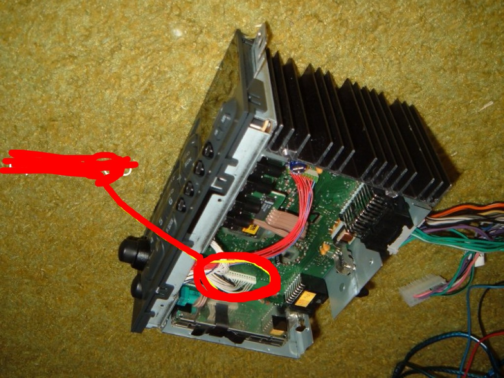
Tuck all your wires neatly into the case and reconnect the green cable and connection you unhooked earlier to the top circuit board set aside earlier. Run your ground out the corner. I attached a round ring terminal to the end of my ground and placed it under the bottom right screw in below picture...
While I had the head unit out, I cleaned the sensor with a qtip and alcohol. My CD player wouldn't play burnt CDs before now it does!! All it needed was a good cleaning!
Our friend toque has a write up on how to clean the eye on his website toquezo6.com! On my older style unit all I had to do was take the metal lid off the top of the case and I could see the eye. Newer ones are a little harder to get to.
Reattach all screws and lid and your good to put it back in the vette and give it a test!!! Make sure all wires are connected to the back of your HEADUNIT including the antenna!
Now is when you will have to unlock the HEADUNIT. Your manual tells you how.
Now if you did the 4th and 5th wires you will need to be on FM radio any station. Now plug in you iPod or other devise into its headphone jack and then into your new input. It will turn off the radio and play the iPod! You must unhook the connector from the face not just your device and it will go back to radio. Crystal clear quality of both now!!!
If you used 1st and 3rd wires you will need to be playing a cd in cd mode. Same thing here plug in the connector then your iPod and it will shut off cd and play your iPod! Unplug connected from faceplate and your back to cd!
This is why I think even the newer style can still use 4th and 5th wires it will just use radio instead of cd.
This is much easier than it seems and you will understand better when your looking directly at your head units "guts" than when looking at my pics.
Any questions don't hesitate to ask!
Tyler

This is what we're starting with....
And here's what we're going for...
Again this only cost about $3 dollars and takes a mild bit of mechanical inclination so I wouldn't recommend attempting this if your not even comfortable removing your head unit yourself. If you are, then by all means your capable of getting the job done. This was the first time I've soldered anything since my young engineers class in the 8th grade but its fairly easy work. So even if you've never touched a soldering iron before you can still do this!
Step one.....
Go to RadioShack and pick up this little guy...
If you don't have a soldering iron, then go ahead and pick one up at RadioShack also, along with a spool of thin soldering wire. I bought the iron with a switch to change the iron from 15watt to 30 watt but found I used it on 30watt setting. You will also need a rotary tool if you dont already have one. I picked mine up at harbor freight for $8 with a coupon and it worked great!
Step two.....
Mark the outline of the radio bezel in the lower left corner of the faceplate of the head unit BEFORE removing anything from the car.... This is after I took it out but here is the mark you need to make with a pencil...
Step three...
If you have a convertible like mine you must remove the waterfall first....next, for all models, remove the center glove box and the center console/radio bezel. You can find a write up on how to do this in the tech forum, or over at vetteessentials.com. Next remove the head unit. PS MAKE SURE YOU KNOW YOUR UNLOCK CODE IF YOUR ANTITHEFT IS ACTIVE ON YOUR HEADUNIT as you will need to unlock it once you reinstall it when your finished. Take out the cd if there's one in it now.
Go ahead and remove your headunit from the car and take it somewhere clean where you won't lose any parts, is well lit, and has an outlet. Since my fianc� doesn't mind me bringing my "projects" in the house, I chose my kitchen island.
Step four...
Go ahead and plug in your soldering iron and let it warm up while you start disassembling the head unit. Turn it upside down on your work area and remove these three screws...
Once the screws are out, pop off the metal lid.... You'll find this underneath...
Go ahead and remove all of the remaining gold screws holding this circuit board down.... I think there were 3 on the board itself, then 3 or 4 more through the case on the sides. Underneath you'll find something similar to this. PS this picture is AFTER I had already unplugged a couple things and added a couple wires.... Ignore them for now.
THIS IS VERY IMPORTANT!!!! My car is a 98 and the Head unit is slightly different from some of the newer ones!!! You need to determine which style you have!!! The easiest way I think is to look at where this cable is on the circuit board.... My 98 is located here....
Newer cars it is located here...
It is very important to identify which style you have as it depends which wires we will cut later! I will refer to them as older style and newer style.
Unhook the green cable and the white row of cables connector circled above from the top circuit board you just removed and set it aside somewhere safe for now.
Step five....
Now you need to remove the face plate and the wires attaching it. It's a little tricky to release all the plastic tabs holding it to the case... Just be patient. Also pull the two ***** off and set them aside. I think once you remove the volume **** you will need to unscrew a little nut to separate it from the face. Put it somewhere safe.
Next remove the tiny little screws holding on the circuit board to the face... I didn't have a socket small enough so I grabbed each with a set of needle nose pliers and very CAREULLY unscrewed them. You don't wanna scratch the circuit board!
Here's what you should have now....
Now remove the plastic piece and the metal pieces circled below.... This again is a little tricky just be mindful of the little plastic clips.
Once removed.... You have this....
That little plastic tab over on the right will be in the way of the jack..... So get out your rotary tool and cut it out to end up with this...
Now you will need to trim the corner off that little metal piece where you removed the plastic tab. Just cut off the corner. Reinstall the plastic and metal pieces.... Now test fit your jack...
If it fits then your good to move on...if not trim a little more with rotary tool. Next mark where you need to drill your hole.... Take some white out or anything else that will transfer and dab it on the metal part of the jack then retest fit... It should transfer to where you need to drill the hole... Not sure what size hole, but it should poke through perfectly flush from the front if you remove the little nut on the new jack.... You won't need it. Make sure before drilling your hole that you are inside your pencil marks from the bezel.
If all is well, move on...
Step six....
Now we get to solder! I used whats called cat5 cable. It's what you use to hook up your modem to your computer or router. Strip the outer layer and you will find small braided wires that are perfect for this job. I had an extra cable around the house, but they are cheap anywhere just cut off the plugs on the ends. I used the blue solid and blue striped as well as green solid and striped.... Then I separated the brown and used the solid brown as my ground.
My hands shake like a Parkinson's patient so I had a couple beers at this point and it steadied my hand a little ; )
Here is what you need to solder on your jack...
Here's a diagram
1 is grounded to case
2 goes to "plugged in" end of cut wire #4 (or #1)
3 goes to "unplugged" end of cut wire #4 (or #1)
4 goes to "unplugged end of cut wire #5 (or #3)
5 goes to " plugged in" end of cut wire #5 (or #3)
This is why it is VERY important to determine which style head unit you have, my 98 was the older style and you had to cut the 4th and 5th wires. The newer style, you have to cut the 1st and 3rd wires!!!!! I learned this the hard way and ruined the headphone port on my ipad. Luckily it was still under warranty and apple replaced it for free! But this is very very important! I've heard that the newer style can also use the 4th and 5th wires also, but not positive.... Will explain why later.
Step seven....
Now install your newly soldered jack into your drilled hole. I added a piece of electrical tape to the inside of the case by the jack so that the soldered connections wouldn't touch the metal case and short out. If its a little lose in the hole dont worry... When you reinstall the circuit board it will hold it tightly in place. I ground down the back of the circuit board slightly where it will make contact with the new jack, but I don't think it's necessary.
Next reinstall the circuit board to your face plate and reinstall your *****. Feed your wires carefully into the main case and snap the face plate back on.
Step eight....
Now your ready to cut the wires on the main connector. Look at it so the little black wire is to the right.....
If you have the older style like mine..... Cut the 4th and 5th wires leaving enough of each end to make soldered connections.
If you have the newer style cut the 1st and 3rd wires.
( PS ive heard you can also use 4th and 5th on newer models but haven't tested this)
Here's the connector again...
Now strip, twist together, and solder your connections as identified above. I also used heat shrink over the connections. If this is your first time soldering, I would practice with some extra wires making these connections! Also put a folded paper towel or something under your wires while soldering over the head unit. If you drip solder on the circuitry you could ruin the whole head unit!!!!!!
Note in my pictures I made the error of using the 1st and 3rd wires so you will see where I made the repairs. You won't have as many connections.
Here's after your connections are soldered and heat shrunk...
Again note I have extra connections due to my mistake mentioned earlier!
Tuck all your wires neatly into the case and reconnect the green cable and connection you unhooked earlier to the top circuit board set aside earlier. Run your ground out the corner. I attached a round ring terminal to the end of my ground and placed it under the bottom right screw in below picture...
While I had the head unit out, I cleaned the sensor with a qtip and alcohol. My CD player wouldn't play burnt CDs before now it does!! All it needed was a good cleaning!
Our friend toque has a write up on how to clean the eye on his website toquezo6.com! On my older style unit all I had to do was take the metal lid off the top of the case and I could see the eye. Newer ones are a little harder to get to.
Reattach all screws and lid and your good to put it back in the vette and give it a test!!! Make sure all wires are connected to the back of your HEADUNIT including the antenna!
Now is when you will have to unlock the HEADUNIT. Your manual tells you how.
Now if you did the 4th and 5th wires you will need to be on FM radio any station. Now plug in you iPod or other devise into its headphone jack and then into your new input. It will turn off the radio and play the iPod! You must unhook the connector from the face not just your device and it will go back to radio. Crystal clear quality of both now!!!
If you used 1st and 3rd wires you will need to be playing a cd in cd mode. Same thing here plug in the connector then your iPod and it will shut off cd and play your iPod! Unplug connected from faceplate and your back to cd!
This is why I think even the newer style can still use 4th and 5th wires it will just use radio instead of cd.
This is much easier than it seems and you will understand better when your looking directly at your head units "guts" than when looking at my pics.
Any questions don't hesitate to ask!
Tyler
Last edited by Tyler_RN_EMT; 03-18-2013 at 02:58 AM.

The following 11 users liked this post by Tyler_RN_EMT:
Akitanut (07-21-2023),
ArmchairArchitect (01-26-2020),
bordnert (01-24-2017),
dabigboss (12-22-2023),
doublenut9 (05-19-2016),
and 6 others liked this post.
The following users liked this post:
tcallebaut1 (07-11-2021)
03-18-2013, 02:52 AM
#3
Pro
Thread Starter
No problem I enjoy this kind of work and encourage others to try something new! It's amazing what you can teach yourself to do if you have a good teacher and a good guide to go by! Lets knock this bs "corvette tax" and get some stuff going!
Tyler

Tyler
03-18-2013, 11:19 AM
#4
Burning Brakes

Member Since: Apr 2002
Location: The Villages FL
Posts: 806
Likes: 0
Received 0 Likes
on
0 Posts
St. Jude Donor '13

Great project and writeup! I need to fix my "no temperature lights" problem and will do this at the same time.
Thanks for sharing...
Don
Thanks for sharing...
Don
03-18-2013, 01:11 PM
#5
Tech Contributor
Member Since: Aug 1999
Location: Should this thoughtful, valuable contribution meet with no acknowledgement or 'thanks' this post----
Posts: 16,382
Received 399 Likes
on
257 Posts
this needs to go into the DIY thread, or I will kill you! contact pewter99 about his permanent DIY thread....great write-up and needs to be preserved.
contact pewter99 about his permanent DIY thread....great write-up and needs to be preserved.
03-18-2013, 01:27 PM
#6
Pro
Thread Starter
03-18-2013, 03:22 PM
#7
Drifting

Great write-up. Do you think your process could be adapetd to locate the aux input anywhere in the car, say inside the center console or other location. Can those wires somehow be routed out of the back of the headunit to allow for this? Just curious. Thanks for your contribution.
03-18-2013, 03:30 PM
#8
Drifting

Member Since: Nov 2006
Location: Plano Texas
Posts: 1,682
Likes: 0
Received 2 Likes
on
2 Posts
St. Jude Donor '08

Great write-up. Do you think your process could be adapetd to locate the aux input anywhere in the car, say inside the center console or other location. Can those wires somehow be routed out of the back of the headunit to allow for this? Just curious. Thanks for your contribution.
03-18-2013, 03:53 PM
#9
Instructor

Tyler, great write-up. I performed this mod as well. The only thing I did differently was to mount the aux plug inside the console adjacent to the fuel door switch. This way I did not take a chance on making a mistake on the radio panel and the connection wire as well as the IPod can be stored inside the console. I thought this was a cleaner look. I recommend making a silent CD to play if you use the CD connections, this way there is no background sound when the IPod is in between songs. You can find info on creating a silent CD by doing a Google search for "silent CD"
03-18-2013, 04:30 PM
#10
Pro
Thread Starter
Great write-up. Do you think your process could be adapetd to locate the aux input anywhere in the car, say inside the center console or other location. Can those wires somehow be routed out of the back of the headunit to allow for this? Just curious. Thanks for your contribution.
MGRED99.... Yes this could easily be done. It would infact be easier than my setup....you wouldn't need to remove the face plate and disassemble all of it nor would you have to use the rotary tool. Make the connections as stated in the write up above, then route your CAT5 cable out the back of the case. You may need to drill a small hole, if you do add some type of rubber gromet. then under the console. You would then connect the new Radioshack jack the same way but glue it to the back side of the plastic trim piece just leaving the jack exposed from inside the glove box or the center console next to the traction button.
The following users liked this post:
ArmchairArchitect (01-26-2020)
03-18-2013, 04:35 PM
#11
Pro
Thread Starter
Tyler, great write-up. I performed this mod as well. The only thing I did differently was to mount the aux plug inside the console adjacent to the fuel door switch. This way I did not take a chance on making a mistake on the radio panel and the connection wire as well as the IPod can be stored inside the console. I thought this was a cleaner look. I recommend making a silent CD to play if you use the CD connections, this way there is no background sound when the IPod is in between songs. You can find info on creating a silent CD by doing a Google search for "silent CD"
Thanks! I chose to place mine in the face plate of the headunit itself to keep everything as "factory looking" as possible, although some cars do come factory with the aux input in the glove box! My fiance's old Scion TC was this way, but her new Jeep Wrangler has it in the head unit. It would be nice to mount it in the center console like you said so that you can both charge and run the unit hidden in the glove box. I found I was constantly wanting to change songs and when it was in the glove box I always had to open everything up just to skip a song. Either way you can make a nice clean "factory appearing" install!!! Also, if you use wires #4 and #5 you don't have to worry about making a blank CD.
Tyler
The following users liked this post:
ArmchairArchitect (01-26-2020)
03-18-2013, 04:38 PM
#12
Pro
Thread Starter
I have heard of a way to "tap in" behind the headunit, but I believe it only worked this way if you have the rear mounted 12 disk changer. I do not have this. I don't know the process for doing this, but I have seen it somewhere on one of the forums before. Hopefully someone will chime in here if they know that process.
Tyler
03-18-2013, 06:38 PM
#13
Burning Brakes
How is the sound quality? I have one of the �boxes� to do the same thing but the sound level is lower than that of the radio. Does this route allow a better matched sound leveling?
03-18-2013, 10:39 PM
#14
Pro
Thread Starter
Tyler
The following users liked this post:
ArmchairArchitect (01-26-2020)
 03-19-2013, 03:27 PM
#16
Race Director

Excellent writeup! I still use my 12 CD changer + 1 dash CD and never get bored on my 15 minute drive to work, but I would definitely do the MP3/Ipod player jack install if I spent more time in my car.
 03-21-2013, 10:10 AM
#20
Administrator


Member Since: Mar 2001
Location: In a parallel universe. Currently own 2014 Stingray Coupe.
Posts: 342,700
Received 19,225 Likes
on
13,932 Posts
C7 of the Year - Modified Finalist 2021
MO Events Coordinator
St. Jude Co-Organizer
St. Jude Donor '03-'04-'05-'06-'07-'08-'09-'10-'11-'12-'13-'14-'15-'16-'17-'18-'19-
'20-'21-'22-'23-'24
NCM Sinkhole Donor
CI 5, 8 & 11 Veteran

Great write up and the pics help a lot. Thanks for documenting this.