UPDATED Again 8/25/13**** Ultimate DIY/FAQ Thread ...It's All in HERE!!
 09-19-2007, 02:01 PM
#1
Team Owner


Thread Starter


***Updated, cleaned up 08/04/12****I finally got around to cleaning this up AGAIN, re-numbering things and removing unnecessary stuff. I also moved some links in here that were former sticky threads to clean up the section. I hope everyone enjoys this thread and if you have something to add by all means post it up and send me a PM to get it added to the list!
Robert
The purpose of this thread is to try and consolidate all of the DIY and How To's posted here in the tech section. I know alot of forum members have posted threads on how to do alot of stuff from swapping out lights to fluid changes and painting calipers. Alot of these threads have some great information and some very helpful pics and tips so in an effort to get everything in one place and save some time searching I encourage you to let me know about a good DIY thread so I can include it here. I am not saying don't post it in the section but let me know and I will add it here so it will be easier to find in the future.
I will start a table of contents in this post and try and update it as things are added...please PM me if you post an article in here so I can update the TOC.
A very useful link Bill Curlee's list of must have info
http://forums.corvetteforum.com/c5-t...ould-have.html
Weights,measurements, ratios, strengths etc http://forums.corvetteforum.com/c5-g...s+measurements
Post #2 C5 Headlight gear replacement ****also see post #22 for other version**
Post #3 Installing Clear Corner Lights
Post #4 Connecting wideband via EGR or A/C Pressure in HP Tuners
Post #5 Reuse original shift boot with C6Z06 shifter/****
Post #6 HOW TO PUT 99-02 PCM into 97-98 Corvette WITH PICS!
Post #7 & 48 How to replace TPM sensor batteries
Post # 8 Narrow band oxygen sensor emulation with a LM-1 wide band
Post # 9 AC Refrigerant charge level
Post #10 Intake manifold Removal
Post #11 How To Fit C6 Fender Guards on a C5
Post #12 DIY Trunk Lid Liner
Post #13 Sun Visor Fix
Post #14 Heated Seats Installation
Post #15 Retractable Antenna Fix
Post #16 How to fit a Pioneer AVIC N1
Post #17 Simplified differential output shaft removal
Post #18 Outside mirror repair
Post #19 Installing interior electrochromic mirror
Post #20 Repair Dim HVAC controller
Post #21 How to fix leaking turn signal housings
Post #22 Headlight gear replacement (version #2)
Post #23 Rocking Seat Fix
Post #24 How to install a FAST 90/90
Post #25 How to install Auot Dimming mirror in car that didn't have one
Post # 28 DIY Rear Hatch Mechanism fix.
Post # 30 How To Refurbish a C5 Hoodliner
Post #31 Z06 screened Front License Plate Mod
Post #32 Popping rear axle fix
Post #33-35 Corbeau A4 Seat and Rail Installation
Post #36 DIY Exhaust Hanger repair - without ordering the hanger.
Post #37 Front License Plate Fresh Air Screen Mod
Post #38 How to refinish your C5 clear Targa Top.....
Post #39 Headlight switch failed. Decided to repair instead of replace…
Post #40 dash removal and HUD install
Post #41 Vette Essential's Full Custom Seat Cover Replacement
Post #42 TheRadioFlyer's LED "halo" tail light mod
Post #43 Vette Essentials: Replace any interior piece: shift boot A4 and MN6, counsol lid, ect
Post #44 bunch of misc links, threads, and DIY's ..if you can't find it elsewhere
Post #45 Leaky rear fix...with pics
Post #46 Replacing TPM batteries
Post #47 Multi-Function Switch / Headlight Switch / Blinker Arm Removal
Post #48 - DIY Flasher Bypass.
Post #50 How to lower your C5 (3 different threads)
Post #51 DIY Repair a curbed polished rim
Post #53-56 Fix airbag light that stays on
Post #58 Power Seat Issues (formerly a sticky thread)
Post #59 Oil Pressure Sender Relocation How To (former sticky)
Post #60 How to fix exterior mirrors with broken swivels (former sticky)
Post #61 C5 Differential Rebuild
Post #62 How To Properly Jack Your C5
Post #63 How to replace your AC compressor
Post #64 Door handle LED install
Post #65 Service ABS, Service Traction Control, Service Active Handling and EBCM Tutorials
Post #66 Evil-Twin's Rotor Cleaning Technique
Post #68 How to Replace Halo Weatherstripping on a C5 Coupe
Post #69 Clutch Install guide from forum member Dope
Post #72 Upgrade TPMS
Post # 73 Oil pressure sensor replacement without cutting or intake removal
Post # 80 The $40 fix for broken side bolsters [pics]
Post #81 Tips on shocks, sways and lowering
Post #82 Clear Corner lights Version #2
Post #83 AntiVenom Mod
Post #84 Flasher Switch
Post #85 Another DIY Jacking Puck thread
Post #86 DIY AR Header Install on my 1997 C5 6 speed car (by bucketlist1957)
Post #87 Z06 rear Brake Duct Template * FREE *
Post #90 Link to C5 DIC Codes
Post #91 Torque Converter Install
Post #92 Lowering C5 the right way
Post # 94 When air comes out of all AC vents: How to Fix w/Pics
Post #95 How-to-repair-EBCM-avoiding-costly-repairs-through-ABSfixer-or-Fleabay
Post #98 Window Motor Rebuild
Post #100 Links to Steering Position Sensor
Post # 101 DIY for adding AUX Input using GM10-AUX do not need COR HAR Harness
Post #102 Headlights stuck in bright / dim Fix
Post # 103 DIY GM #12102635 for TPMS upgrade
Post #104 Sideskirt DIY...make your own...10-13-2011
Post #106 How to remove stock control arm bushings with only a vise and free Autozone Loaner Tools.
Post #107 Lazymans Rocking Seat Fix
Post # 108 Weights, measurements, strengths etc.
Post #109 Fuel Regular, Premium, Real Gas
Post #110 Planning on Wheels and Tires? Not sure which tires to go with? AH/TC issues?
Post #111 Making the C5 go the distance!
Post #112 The Anatomy of a Hydraulic Lifter
Post #113 Multifinction Turn Signal Lever
Post #114 Engine Grounds
Post #115 1997-2004 PCM Pinout
Post #116 C5 Ignition Switch Repair
Post #117 C5 T56 Rebuild 5th-6th Extension Shaft Details
Post #118 Leak Checks
Post #119 Opinions on Propshaft Rubber Couplings
Post #120 ACA HID install prep - bulb jiggle "fix"
Post #122 Sound Deadening and Stereo Install (step by step)
Post # 123 Fast 92 intake with LS2 Throttle Body install
Post # 124 An Alternative Fix For The P1416 Code
Post # 125 C5 steering wheel with a regular steering wheel puller
Post # 127 How to get your seat out when there is no power or broke
Post # 128 Mesh Side Cove DIY
Post #129 Dipstick Mod
Post #132 How to check fluid level in A4 Transmission
Post #135 18 minute hazard switch replacement
Post #136 DRM transmission cooler install process pictures and helpful hints
Post #142 Adding AUX/iPod jack into the stock C5 Headunit
Post #143 Install a DRM Transmission cooler
Post #144 How to stripe your Vette using the PlastiDip product.
Post #145 How to install 9000 pound twin post lift
Last edited by pewter99; 08-25-2013 at 09:19 PM. Reason: clean up
 09-19-2007, 02:06 PM
#2
Team Owner
Thread Starter
Parts needed:
brass gear kit
10mm socket
13mm socket
1/4 drive ratchet
magnetic pick-up tool
phillips screwdriver
brass gear kit (you can get this from Rodney Dickman) at www.rodneydickman.com (yes I know he sells Fiero parts...trust me he sells the gears for the headlight) you can order online or call him. he is a super nice guy and ships the stuff Priority Mail.
you can also buy the kit thru MidAmerica.
Ok, lets get started. Turn the headlights on or manually crank up the bad light. If you turned the lights on you can unplug the bad light and turn the other light off so as not to kill the battery.
Remove the black plastic headlight surround, 3 Phillips head screws. Now look inside the opening and you will see there are basically 5 nuts/bolts that hold the assembly in place.
After these bolts /nuts are removed lift the assembly out
Turn the whole piece on its side and you will see the round cover which is secured with 3 little screws
Remove these screws and take off the cover.
Now install the new gears and replace the cover.
Install is the reverse of removal. Plug everything back in and you should have this.
Last edited by pewter99; 03-19-2018 at 12:27 PM.
09-19-2007, 10:22 PM
#3
Melting Slicks

Here is a great write up in a thread started by 95BlueBomber. I know this isn't your everyday mod so, since it is already a sticky in the Scan and Tune section, I will just post a link to it in case someone starts here looking for it.
http://forums.corvetteforum.com/show....php?t=1705471
http://forums.corvetteforum.com/show....php?t=1705471
Last edited by 'VETTE PHASE; 09-19-2007 at 10:25 PM.
09-19-2007, 11:19 PM
#4
Drifting

A note regarding the shifter install itself: When you put the new shifter assembly in, make sure you get the the grooved part of the shaft lined up with the collar correctly (peek in the hole in the collar and you'll see if it's lined up). Also if the collar is not tight enough when you release the neutral locking pin and rock the shifter side to side you'll see that the collar will slip relative to the shaft. If this happens it will be hard to get into reverse...
What I did with the old boot was slice the stitches in the folded over area, and two stitches into the outwardly visible section of the boot (this allows for the bigger diameter **** to fit into the old boot). If you find that the **** doesn't quite fit sparingly remove an additional stitch one at a time until it fits. You don't want to cut too far down as you'll make the boot too short. Turn the boot inside out, then take an exacto knife and slice into the glue that the factory uses to hold down the folded over area until the folded over area is freed from itself (this part is a little tough, but take your time, you'll get it). Most of the folded over area will be trimmed off later, but it needs to be separated to help the leather to not bulge at the base of the **** when installed. I then got some steel wire, doubled it over (for strength), inserted the new **** in the boot (in the proper orientation, you'll understand once you look at it). Then take the wire, wrap it around the boot with the **** in place, twist the ends together. Use pliers to tighten (not too much as you'll break the wire) but enough to cause the wire/leather to sink into the groove in the new ****...Then snip off the excess wire and tuck the twisted together end of the wire into the groove. Trim off the excess leather to expose the area where the screw goes in to attach the **** to the shaft. Invert the boot (right side in) and check to see if the stitches of the boot line up with the stitches in the ****.. Twist it to line it up if it is not..Lastly, I liberally applied Lexol leather conditioner to the inside and outside of the boot to make it supple again..All done...Hope this helps...Let me know if there are parts I need to clarify better...


What I did with the old boot was slice the stitches in the folded over area, and two stitches into the outwardly visible section of the boot (this allows for the bigger diameter **** to fit into the old boot). If you find that the **** doesn't quite fit sparingly remove an additional stitch one at a time until it fits. You don't want to cut too far down as you'll make the boot too short. Turn the boot inside out, then take an exacto knife and slice into the glue that the factory uses to hold down the folded over area until the folded over area is freed from itself (this part is a little tough, but take your time, you'll get it). Most of the folded over area will be trimmed off later, but it needs to be separated to help the leather to not bulge at the base of the **** when installed. I then got some steel wire, doubled it over (for strength), inserted the new **** in the boot (in the proper orientation, you'll understand once you look at it). Then take the wire, wrap it around the boot with the **** in place, twist the ends together. Use pliers to tighten (not too much as you'll break the wire) but enough to cause the wire/leather to sink into the groove in the new ****...Then snip off the excess wire and tuck the twisted together end of the wire into the groove. Trim off the excess leather to expose the area where the screw goes in to attach the **** to the shaft. Invert the boot (right side in) and check to see if the stitches of the boot line up with the stitches in the ****.. Twist it to line it up if it is not..Lastly, I liberally applied Lexol leather conditioner to the inside and outside of the boot to make it supple again..All done...Hope this helps...Let me know if there are parts I need to clarify better...
09-20-2007, 07:34 AM
#5
Race Director

HOW TO 99-02 PCM into 97-98 Corvette WITH PICS!
http://forums.corvetteforum.com/show....php?t=1750377
http://forums.corvetteforum.com/show....php?t=1750377
09-20-2007, 10:31 PM
#7
Drifting

Here is a write-up I did a few years ago.
How to use a wide-band oxygen sensor in place of a stock narrow band:
http://www.kanesbrain.com/Corvette/wbo2.html
Could also be called narrow band oxygen sensor emulation with a LM-1 wide band.
If anyone has any questions about this please feel free to PM me.
How to use a wide-band oxygen sensor in place of a stock narrow band:
http://www.kanesbrain.com/Corvette/wbo2.html
Could also be called narrow band oxygen sensor emulation with a LM-1 wide band.
If anyone has any questions about this please feel free to PM me.
Last edited by torchredfrc; 11-25-2012 at 10:18 PM. Reason: Moved the howto to a new URL
09-20-2007, 10:52 PM
#8
This is a post I made a while back to address AC problems. Nothing in the AC system works right if the chg level is incorrect. It's often the first thing we need to verify.
How do tell if my AC is short on refrigerant? This question keeps coming back so I thought I would offer up my way of checking and correcting AC charge problems. First we need to determine what the correct charge looks like because the pressures vary a great deal depending on engine speed, humidity, ambient temp and some other things. Shown below is a chart I’ve used for years with some success.
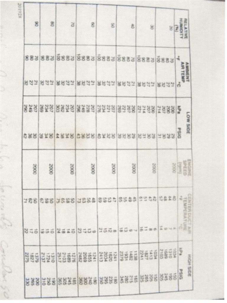
Notice that humidity has a strong effect and that all readings are taken at 2000 rpm.
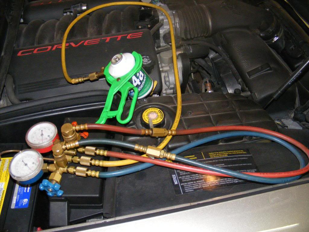
OK, how do we measure these pressures. The pic below shows the equipment needed. Yeah, I know a lot of people just use the Walmart can that reads the low side only and do fine. I just like doing it this way and the whole setup can be bought for less than $60; not big bucks for a tool nut. You don’t need one off the Snap On truck for our purposes. Look here:
http://www.harborfreight.com/cpi/cta...emnumber=92649
Don’t forget the clamp that goes around the can of R134 and punctures the side of it.
Look here: http://www.ctd4ac.com/actools6.asp
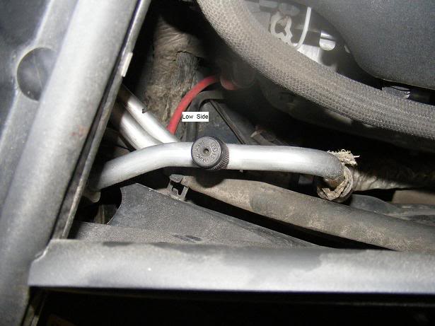
Now that we have our new toy, how do we use it? Make sure both hand wheels on the gage set are closed. Turn them clockwise until they seat. Look under the hood of your C5 on the pass side and you will see the test ports covered with a black plastic cap. Unscrew the caps and snap the gage hose connectors onto the test ports with the engine off. You cannot hook them up wrong because the low and high side test ports are different.
LOW SIDE-rear of eng compartment
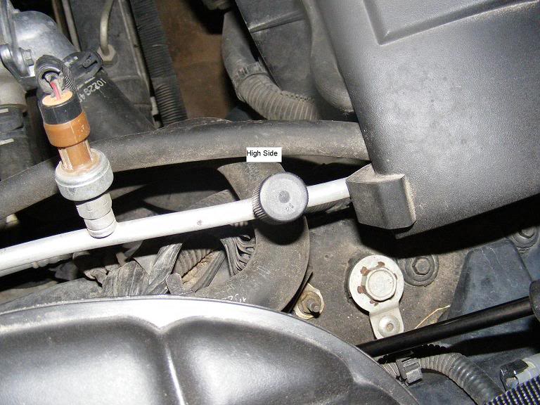
HIGH SIDE-front of eng compartment
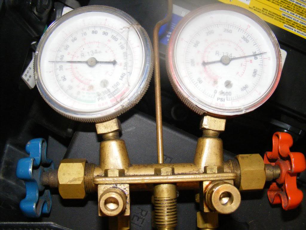
Here the hoses are connected
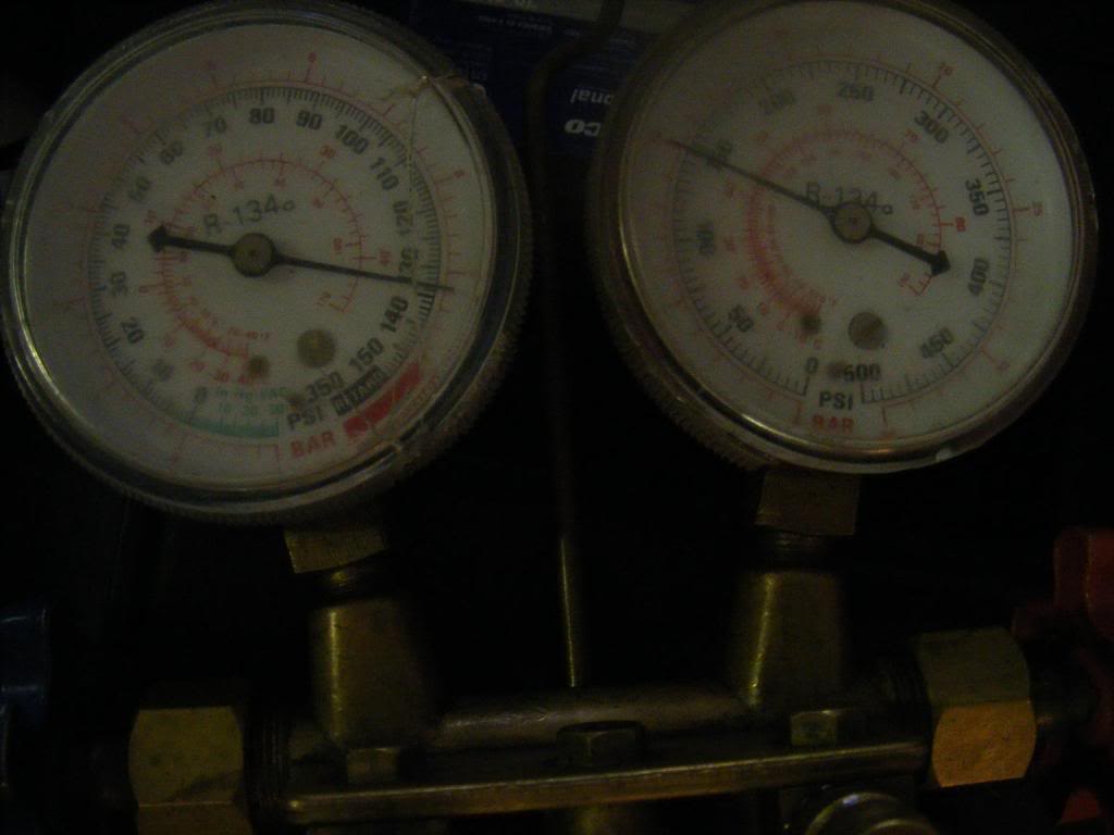
Once you’re hooked up with the eng off you are reading static pressure. It will be over 100 on both gages on a hot day. Both gages should be about the same, if not, you have other problems. The left gage is low side and the right is high side. See the pic above showing static pressure on my C5.
Now we need to start the eng, turn AC to it’s coldest setting, fastest fan speed, lower both windows and place a thermometer in the center air vent. When you start the eng the low side will start to drop and the high side will go up. If this doesn’t happen, your compressor is not working. Look at the front of the compressor to see if the clutch is turning with the rest of the pulleys. If it isn’t, and your static pressures are close to zero, the computer may have shut down the compressor to avoid damage. Disconnecting the batt cable for a few minutes will usually fix this. If that doesn’t work, your problem is beyond the scope of this post.
Below is a pic showing correct pressure, both low and high, for a 60% humidity, 100 degree day and an eng speed of 2000 rpm. You younger guys can probably find a Hooters girl to press on the gas pedal, the rest of us use a wife or grandkid. My center duct temp was 50 degrees at this point. Look at the chart above and you will see we’re OK. Actually the duct temp is much better than the chart. Score one for GM engineering (wonder if the same guys did the column lock). If this is what you see your AC is working well and you are wasting your time reading this post.
If your readings are a bit low on both gages and duct temp is too high your car is probably undercharged. Now connect your can clamp to the center hose(yellow) and clamp it around your can of R134. Then gently loosen the yellow hose connector where it attaches to the gages. When a clear or white mist comes out you have purged that line of the air in it and it is full of refrigerant. If you skip this step the air in the hose will be added to your system.
To add 134 you simply open the left hand wheel gently. Do not touch the right hand wheel. Keep the high side closed. You should now see the low side pressure increase because we have connected the can to the system and it will typically have up to 90 psi on a warm day. Make sure you keep the can sitting on its base to keep from pumping liquid into the system. The compressor cannot deal with liquid very well. Allow the 134 time to enter the system while you periodically close the left hand valve to get an accurate reading of the low side pressure without the pressure of the can being involved. While you’re doing this keep an eye on the high side gage (RH) and do not allow it to exceed the chart pressure. There are few things in life more exciting than blowing an AC hose with your head under the hood. Don’t ask me how I know this.
When both low and high side readings approximate the chart your center duct temp should match or be lower than the chart . Close the left hand valve, shut down the engine, remove your gages and replace the caps on the test ports. You are now a highly skilled AC technician and may want to open your own business.
A NOTE ABOUT LEAKS. If you used half a can(6 oz) you have replaced 20% of the total system charge. If that amount leaked out over a period of 5 years don’t waste your time trying to find the leak. Just plan on recharging in another 5 years. If, on the other hand, you just added refrigerant a month ago you need to find and fix the leak or adding refrig will be a monthly service.
This isn’t a Bible. There are a lot of different ways to go about this. It’s just the way I do it and it’s always worked well for me. Some people are intimidated by AC repair. It’s a whole lot simpler than some of the stuff I read on this forum. Heck, we’ve got guys here who could repair their PCM with bubble gum and baling wire alongside the road at night! Give this a try, you might like it!
How do tell if my AC is short on refrigerant? This question keeps coming back so I thought I would offer up my way of checking and correcting AC charge problems. First we need to determine what the correct charge looks like because the pressures vary a great deal depending on engine speed, humidity, ambient temp and some other things. Shown below is a chart I’ve used for years with some success.
Notice that humidity has a strong effect and that all readings are taken at 2000 rpm.
OK, how do we measure these pressures. The pic below shows the equipment needed. Yeah, I know a lot of people just use the Walmart can that reads the low side only and do fine. I just like doing it this way and the whole setup can be bought for less than $60; not big bucks for a tool nut. You don’t need one off the Snap On truck for our purposes. Look here:
http://www.harborfreight.com/cpi/cta...emnumber=92649
Don’t forget the clamp that goes around the can of R134 and punctures the side of it.
Look here: http://www.ctd4ac.com/actools6.asp
Now that we have our new toy, how do we use it? Make sure both hand wheels on the gage set are closed. Turn them clockwise until they seat. Look under the hood of your C5 on the pass side and you will see the test ports covered with a black plastic cap. Unscrew the caps and snap the gage hose connectors onto the test ports with the engine off. You cannot hook them up wrong because the low and high side test ports are different.
LOW SIDE-rear of eng compartment
HIGH SIDE-front of eng compartment
Here the hoses are connected
Once you’re hooked up with the eng off you are reading static pressure. It will be over 100 on both gages on a hot day. Both gages should be about the same, if not, you have other problems. The left gage is low side and the right is high side. See the pic above showing static pressure on my C5.
Now we need to start the eng, turn AC to it’s coldest setting, fastest fan speed, lower both windows and place a thermometer in the center air vent. When you start the eng the low side will start to drop and the high side will go up. If this doesn’t happen, your compressor is not working. Look at the front of the compressor to see if the clutch is turning with the rest of the pulleys. If it isn’t, and your static pressures are close to zero, the computer may have shut down the compressor to avoid damage. Disconnecting the batt cable for a few minutes will usually fix this. If that doesn’t work, your problem is beyond the scope of this post.
Below is a pic showing correct pressure, both low and high, for a 60% humidity, 100 degree day and an eng speed of 2000 rpm. You younger guys can probably find a Hooters girl to press on the gas pedal, the rest of us use a wife or grandkid. My center duct temp was 50 degrees at this point. Look at the chart above and you will see we’re OK. Actually the duct temp is much better than the chart. Score one for GM engineering (wonder if the same guys did the column lock). If this is what you see your AC is working well and you are wasting your time reading this post.
If your readings are a bit low on both gages and duct temp is too high your car is probably undercharged. Now connect your can clamp to the center hose(yellow) and clamp it around your can of R134. Then gently loosen the yellow hose connector where it attaches to the gages. When a clear or white mist comes out you have purged that line of the air in it and it is full of refrigerant. If you skip this step the air in the hose will be added to your system.
To add 134 you simply open the left hand wheel gently. Do not touch the right hand wheel. Keep the high side closed. You should now see the low side pressure increase because we have connected the can to the system and it will typically have up to 90 psi on a warm day. Make sure you keep the can sitting on its base to keep from pumping liquid into the system. The compressor cannot deal with liquid very well. Allow the 134 time to enter the system while you periodically close the left hand valve to get an accurate reading of the low side pressure without the pressure of the can being involved. While you’re doing this keep an eye on the high side gage (RH) and do not allow it to exceed the chart pressure. There are few things in life more exciting than blowing an AC hose with your head under the hood. Don’t ask me how I know this.
When both low and high side readings approximate the chart your center duct temp should match or be lower than the chart . Close the left hand valve, shut down the engine, remove your gages and replace the caps on the test ports. You are now a highly skilled AC technician and may want to open your own business.
A NOTE ABOUT LEAKS. If you used half a can(6 oz) you have replaced 20% of the total system charge. If that amount leaked out over a period of 5 years don’t waste your time trying to find the leak. Just plan on recharging in another 5 years. If, on the other hand, you just added refrigerant a month ago you need to find and fix the leak or adding refrig will be a monthly service.
This isn’t a Bible. There are a lot of different ways to go about this. It’s just the way I do it and it’s always worked well for me. Some people are intimidated by AC repair. It’s a whole lot simpler than some of the stuff I read on this forum. Heck, we’ve got guys here who could repair their PCM with bubble gum and baling wire alongside the road at night! Give this a try, you might like it!
Last edited by Plasticfan; 06-19-2012 at 11:16 AM. Reason: refresh pics
09-21-2007, 05:06 PM
#9
Pro

Member Since: Oct 2004
Location: Edmond Ok
Posts: 538
Likes: 0
Received 0 Likes
on
0 Posts
I don't want to take credit for this, I took it from someone elses site, a very good write-up on getting the intake manifold off for either the check valve or oil pressure sending unit.
http://pages.infinit.net/vette747/IntakeManifold
Great to have a DIY thread.
If you ever break the hard plastic hose that is hooked up on the rear of the intake manifold you can route a vacuum hose to below the battery. There are two plastic hoses under the battery, one routes to the firewall (don't cut this one) the other routes to the wire harness and to the back of the intake manifold. Just cut and slip the vacuum hose on, route carefull, use ties to keep in place.
Other DIY on this site
http://pages.videotron.com/vette747/
Last edited by djengr; 03-11-2008 at 11:14 PM. Reason: Added a website
09-23-2007, 01:56 AM
#10
Tech Contributor
Member Since: Dec 2003
Location: Horncastle Lincolnshire, England
Posts: 19,384
Likes: 0
Received 79 Likes
on
61 Posts
2023 C5 of the Year Finalist - Unmodified

Heres a link. maybe the mods can move the post into the thread.
How To Fit C6 Fender Guards to a C5:
http://forums.corvetteforum.com/show...=fender+guards
How To Fit C6 Fender Guards to a C5:
http://forums.corvetteforum.com/show...=fender+guards
09-23-2007, 02:03 AM
#11
Tech Contributor
Member Since: Dec 2003
Location: Horncastle Lincolnshire, England
Posts: 19,384
Likes: 0
Received 79 Likes
on
61 Posts
2023 C5 of the Year Finalist - Unmodified
I'd been seeing the trunk lid liners on some of the members Vettes but being a good Yorkshireman, the $150 price tag seemed a bit steep.
Had a bit of a DIY morning and made one up myself
A sheet of pegboard - Home Depot $3
A roll of black carpet from Walmart - $8
Spray Glue - Lowes $4
Velcro - Lowes $8
I made a template from some wrapping paper and transferred it to cardboard. Then used the template to cut the pegboard. Shaped the edges to make it fit the space using a rotary cutting disc. Glued the carpet to the pegboard leaving a 2" strip. Folded that over the edges and stapled around the edge after priming with the spray on glue.
Fixing proved tricky. I tried velcro on the V Channels on the inside of the trunk lid but the weight pulled it away continually. I decided to use push fit studs which hold the liner in place a little better. Four studs were a few extra $ from Autozone.
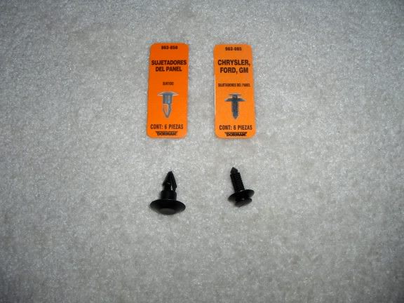
Mark positions for the studs carefully. Drill holes through the liner into the V Frame. The stud pushes through and fits tightly into the frame behind. There are 2 studs at the top and 2 at the bottom.
Most Important: Be very careful not to press too hard and drill through the trunk lid
Voila, the end product:
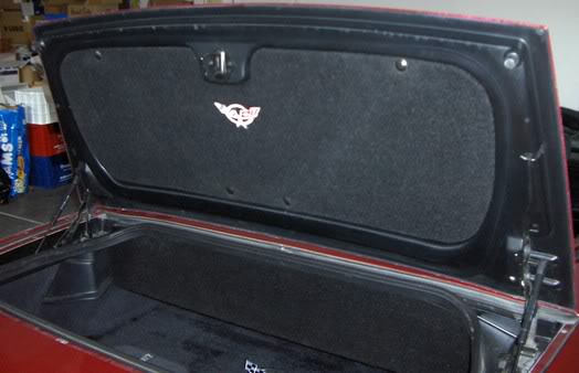
The logo was embroidered by my wife. You could buy the commercial GM logo but that would add to the cost.
An enhancement may be to fit some foam blocks at the lower outer corners. This would prevent some minor flexing
Had a bit of a DIY morning and made one up myself
A sheet of pegboard - Home Depot $3
A roll of black carpet from Walmart - $8
Spray Glue - Lowes $4
Velcro - Lowes $8
I made a template from some wrapping paper and transferred it to cardboard. Then used the template to cut the pegboard. Shaped the edges to make it fit the space using a rotary cutting disc. Glued the carpet to the pegboard leaving a 2" strip. Folded that over the edges and stapled around the edge after priming with the spray on glue.
Fixing proved tricky. I tried velcro on the V Channels on the inside of the trunk lid but the weight pulled it away continually. I decided to use push fit studs which hold the liner in place a little better. Four studs were a few extra $ from Autozone.
Mark positions for the studs carefully. Drill holes through the liner into the V Frame. The stud pushes through and fits tightly into the frame behind. There are 2 studs at the top and 2 at the bottom.
Most Important: Be very careful not to press too hard and drill through the trunk lid
Voila, the end product:
The logo was embroidered by my wife. You could buy the commercial GM logo but that would add to the cost.
An enhancement may be to fit some foam blocks at the lower outer corners. This would prevent some minor flexing
09-23-2007, 02:08 AM
#12
Tech Contributor
Member Since: Dec 2003
Location: Horncastle Lincolnshire, England
Posts: 19,384
Likes: 0
Received 79 Likes
on
61 Posts
2023 C5 of the Year Finalist - Unmodified
I had a problem with the mirror separating from the visor and I tried a couple of things before I got one that worked. I used zip ties:
Pull the mirror away from the housing gently. Stick a piece of 3M double sided tape along the inside edge of the top of the mirror between the two holes in the visor.
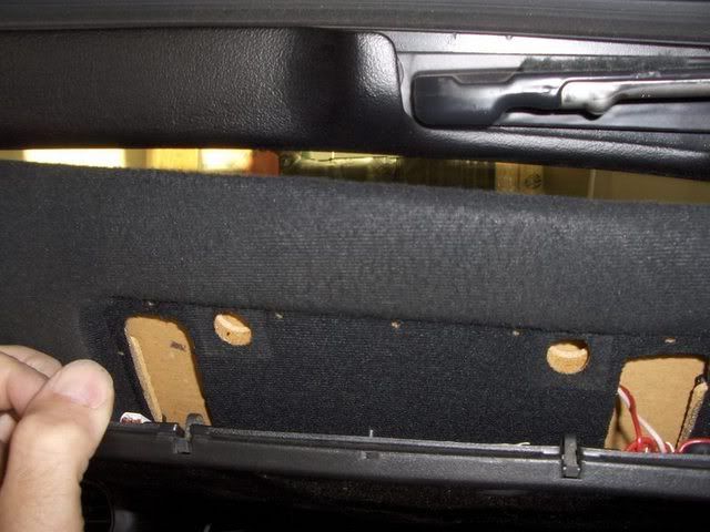
Thread a small zip tie through each hole from the back and outside of the hole, with the “head” of the tie located in the large rectangular recess. Pull the tail of the zip tie towards you and thread from inside to out through the hole in the locating pin. Push the tail through the head loosely at first.
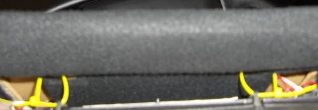
Use needle nosed pliers (holding the tail) and a precision screwdriver (pushed against the head) to tighten the zip ties. Be very careful when pulling the ties tight not to pinch the lighting wires which run through the same hole. Once tight, snip the spare tail of the tie but carefully so as not to snip the electrical wires.
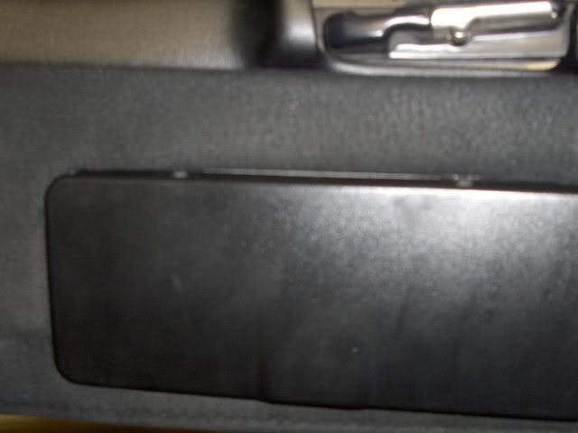
Push the mirror back into its housing and press firmly against the double sided tape.
Should be good as new
Pull the mirror away from the housing gently. Stick a piece of 3M double sided tape along the inside edge of the top of the mirror between the two holes in the visor.
Thread a small zip tie through each hole from the back and outside of the hole, with the “head” of the tie located in the large rectangular recess. Pull the tail of the zip tie towards you and thread from inside to out through the hole in the locating pin. Push the tail through the head loosely at first.
Use needle nosed pliers (holding the tail) and a precision screwdriver (pushed against the head) to tighten the zip ties. Be very careful when pulling the ties tight not to pinch the lighting wires which run through the same hole. Once tight, snip the spare tail of the tie but carefully so as not to snip the electrical wires.
Push the mirror back into its housing and press firmly against the double sided tape.
Should be good as new
09-23-2007, 02:18 AM
#13
Tech Contributor
Member Since: Dec 2003
Location: Horncastle Lincolnshire, England
Posts: 19,384
Likes: 0
Received 79 Likes
on
61 Posts
2023 C5 of the Year Finalist - Unmodified
I bought my kit from Sports Imports. They have a good range and I went for the Universal Model (Product Code SIL-01) which at the time cost $160. It was particularly good because the element design allows you to trim the pads to fit the seat.
http://www.seatheater-heatedseats.co...OVMTC=standard
The kit came with very clear installation instructions. Each seat kit included a 9” x 18” backpad, a 9” x 18” seat pad, 1 electronic temperature control module, 1 dual temp high/low bi-color illuminated round switch and cable ties and insulating tape.
First disconnect the battery. Make sure you can reactivate your radio if you have the security code set. There are instructions in the Forum sticky by Leaftye.
A good wiring diagram comes with the kit.
I used the Vette Essentials website for instructions on removing the seats and the seat covers.
http://www.vetteessentials.com/instr...er_change.html
I also used the VE instructions to remove the console:
http://www.vetteessentials.com/instr...t_install.html
Seats: Run down to individual steps to 17c but stop before removing the bottom covers. I then worked the Velcro fastening inside the pads loose. Take care because the hooks re very sharp. Work out the size of pads you need and trim the pads to size. Slide the lower pad into the gap between the cover and the pad and route the wires out of the back of the seat. My kit was adhesive backed to hold the elements in place. There are connectors on the wiring harness which allow you to make the connections later. Fix the back pad into place and replace the seat cover.
Console: Dismantle the console following the instructions to step 3 to allow you to run the wires forward underneath the console to the switch mounting position. You may feel you can route the wires without stripping the console completely. Run the harness to the ashtray area from the rear of the console making sure you leave enough wire to connect to the seat looms. Run the hot wire under the edge of the console area and down into the passenger footwell to emerge next to the lower fuse panel. This is a bit fiddly. I used a wire coat hanger to thread the wire down. An alternative would be to route it directly under the carpet from the rear of the seats to the passenger footwell.
Dismantle the ashtray unit. Take off the outer door and retain. Remove the inner door of the ashtray and discard
Cut a slot in the rear side of the ashtray mount to allow the wires and connectors to route out from the switches.
I used a small black plastic faceplate to mount the switches. Drill 2 holes 5/8” for the switches to sit snug on the plate. Pull the main wiring connector through the hole and attach to the switch. Fit the switch snug in the hole until it clicks in place. Fit the faceplate into the ashtray and screw in from the sides to hold it in place.
Reassemble the console taking care not to pinch any wires. Pull the wires through the ashtray hole. Connect to the switches.
Slot the ashtray back into place.
Reinstall the seats leaving access to the wires. Connect the wires from the back of the seats to the main harness connectors and secure the wires if necessary.
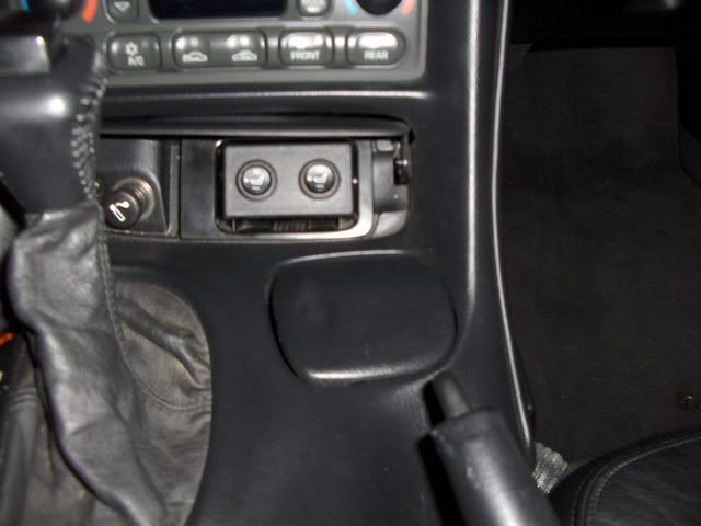
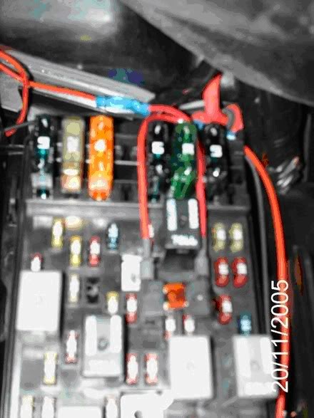
Connect the hot wire to a switched power supply. You can buy spade type connectors from the Company which splice onto the hot lead and will slot directly into the fuse slot in the fuse panel. The attached pic shows each wire individually attached to ~20 and #22.
Hook the ground wire to a suitable ground. I ran through the bulkhead to the ground behind the passenger headlight.

There are other grounds nearby. There's one located under the bulge of rug found beneath the dash panel on the passenger side. It’s that little overhang of carpeting located just off to the left-bottom corner of the glovebox
Reconnect the battery and test the seats.
Best Mod I ever did.
Another member posted an alternative switch mount on the AH panel. This is no use if like me you have the ride control switch
http://www.seatheater-heatedseats.co...OVMTC=standard
The kit came with very clear installation instructions. Each seat kit included a 9” x 18” backpad, a 9” x 18” seat pad, 1 electronic temperature control module, 1 dual temp high/low bi-color illuminated round switch and cable ties and insulating tape.
First disconnect the battery. Make sure you can reactivate your radio if you have the security code set. There are instructions in the Forum sticky by Leaftye.
A good wiring diagram comes with the kit.
I used the Vette Essentials website for instructions on removing the seats and the seat covers.
http://www.vetteessentials.com/instr...er_change.html
I also used the VE instructions to remove the console:
http://www.vetteessentials.com/instr...t_install.html
Seats: Run down to individual steps to 17c but stop before removing the bottom covers. I then worked the Velcro fastening inside the pads loose. Take care because the hooks re very sharp. Work out the size of pads you need and trim the pads to size. Slide the lower pad into the gap between the cover and the pad and route the wires out of the back of the seat. My kit was adhesive backed to hold the elements in place. There are connectors on the wiring harness which allow you to make the connections later. Fix the back pad into place and replace the seat cover.
Console: Dismantle the console following the instructions to step 3 to allow you to run the wires forward underneath the console to the switch mounting position. You may feel you can route the wires without stripping the console completely. Run the harness to the ashtray area from the rear of the console making sure you leave enough wire to connect to the seat looms. Run the hot wire under the edge of the console area and down into the passenger footwell to emerge next to the lower fuse panel. This is a bit fiddly. I used a wire coat hanger to thread the wire down. An alternative would be to route it directly under the carpet from the rear of the seats to the passenger footwell.
Dismantle the ashtray unit. Take off the outer door and retain. Remove the inner door of the ashtray and discard
Cut a slot in the rear side of the ashtray mount to allow the wires and connectors to route out from the switches.
I used a small black plastic faceplate to mount the switches. Drill 2 holes 5/8” for the switches to sit snug on the plate. Pull the main wiring connector through the hole and attach to the switch. Fit the switch snug in the hole until it clicks in place. Fit the faceplate into the ashtray and screw in from the sides to hold it in place.
Reassemble the console taking care not to pinch any wires. Pull the wires through the ashtray hole. Connect to the switches.
Slot the ashtray back into place.
Reinstall the seats leaving access to the wires. Connect the wires from the back of the seats to the main harness connectors and secure the wires if necessary.
Connect the hot wire to a switched power supply. You can buy spade type connectors from the Company which splice onto the hot lead and will slot directly into the fuse slot in the fuse panel. The attached pic shows each wire individually attached to ~20 and #22.
Hook the ground wire to a suitable ground. I ran through the bulkhead to the ground behind the passenger headlight.
There are other grounds nearby. There's one located under the bulge of rug found beneath the dash panel on the passenger side. It’s that little overhang of carpeting located just off to the left-bottom corner of the glovebox
Reconnect the battery and test the seats.
Best Mod I ever did.
Another member posted an alternative switch mount on the AH panel. This is no use if like me you have the ride control switch
Last edited by pewter99; 03-05-2008 at 09:15 AM.
09-23-2007, 02:21 AM
#14
Tech Contributor
Member Since: Dec 2003
Location: Horncastle Lincolnshire, England
Posts: 19,384
Likes: 0
Received 79 Likes
on
61 Posts
2023 C5 of the Year Finalist - Unmodified
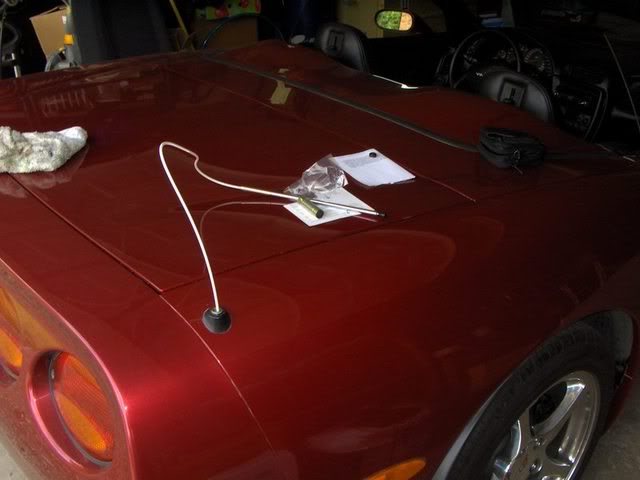
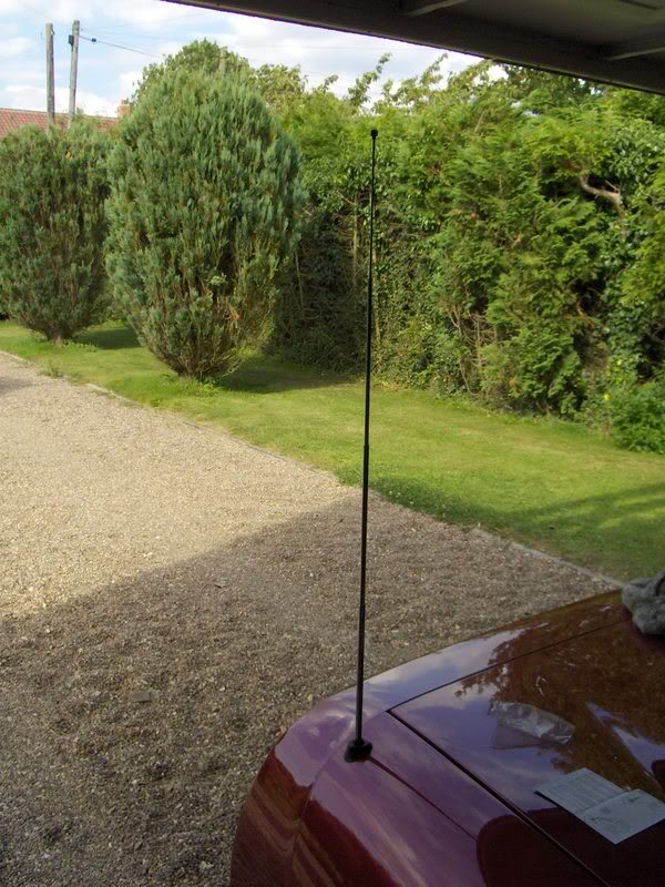
How To Replace a Defective Telescopic Antenna
Now this is a simple mod and the OEM assembly with motor is $130+. You'll know you have the problem because the antenna won't fully retract
Parts:
Adjustable wrench
GM OEM Power Antenna Replacement ($13 E Bay).
Make sure the antenna is fully retracted and that the radio is off
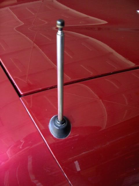
Remove the antenna mounting nut located on the base of the mast on the outside of the car. If the mast is bent it may be necessary to cut off the old mast). If you can't all of the plastic cable out as one piece, (sometimes the plastic gets really hard and breaks into pieces then falls down into the motor), you can just pull the motor after you have pulled the mast out and get all of the pieces out. To do that you'll need to take out the outer right turn signal housing.
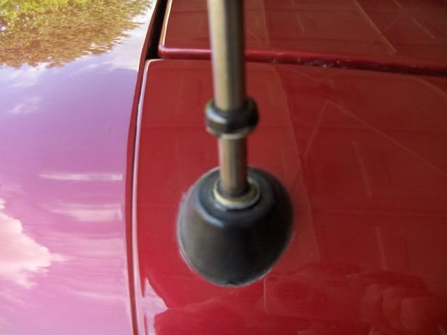
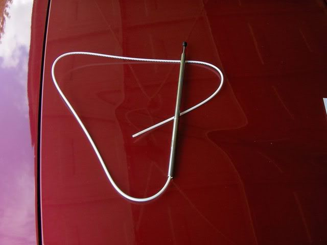
Turn on the radio and pull out the old mast and serrated cable completely out of the antenna motor. (Note which way the serrations on the cable are facing)
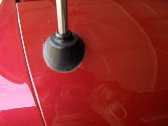
Feed the serrated cable of the new mast into the antenna hole and stop when resistance is felt. (about 12”). Make sure the cable is fed in with the teeth the same way the old cable came out.
Turn the radio off to lower the antenna until the serrated cable catches.. You may have to cycle the antenna a few times until the cable catches the gear mechanism and retracts into the antenna motor.
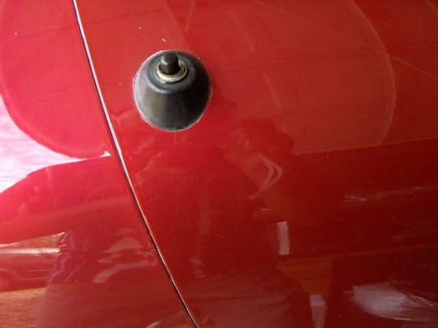
Replace and tighten the antenna nut into the mast base.
Turn on and make sure that the mast fully extends without binding. Clean the surface of the antenna to remove any adhesive etc.
10 minute job.
If you encounter a stuck mast here’s advice from the mast vendor:
You see the new "Retaining Sleeve" (silver, 2 inches or so, with slots) on the shaft of the new antenna mast, the original one is most likely a little corroded/frozen into the shaft of your antenna No problem : You are in need of what I refer to as the "snap and tap" technique of mast removal
Turn radio on and let cycle to as much extension as is currently possible
Take hold of the thickest metal mast section (closest to fender) with you thumb and forefinger about 2-3 inches above the top of the antenna shaft hole
Push the thickest mast section into the shaft (as much as it will go within that 2-3 inches)
Hold tightly with thumb and forefinger and Snap your Wrist upward.....you will here the mast bottom "tap" the bottom of the frozen in place retaining sleeve (what this is all about) Repeat this over and over again In-Snap-Tap-Repeat Short Firm Bursts of Energy Focusing the energy blow to the point of the tap This will free the retaining sleeve little by little till it comes out completely
Now this is a simple mod and the OEM assembly with motor is $130+. You'll know you have the problem because the antenna won't fully retract
Parts:
Adjustable wrench
GM OEM Power Antenna Replacement ($13 E Bay).
Make sure the antenna is fully retracted and that the radio is off
Remove the antenna mounting nut located on the base of the mast on the outside of the car. If the mast is bent it may be necessary to cut off the old mast). If you can't all of the plastic cable out as one piece, (sometimes the plastic gets really hard and breaks into pieces then falls down into the motor), you can just pull the motor after you have pulled the mast out and get all of the pieces out. To do that you'll need to take out the outer right turn signal housing.
Turn on the radio and pull out the old mast and serrated cable completely out of the antenna motor. (Note which way the serrations on the cable are facing)
Feed the serrated cable of the new mast into the antenna hole and stop when resistance is felt. (about 12”). Make sure the cable is fed in with the teeth the same way the old cable came out.
Turn the radio off to lower the antenna until the serrated cable catches.. You may have to cycle the antenna a few times until the cable catches the gear mechanism and retracts into the antenna motor.
Replace and tighten the antenna nut into the mast base.
Turn on and make sure that the mast fully extends without binding. Clean the surface of the antenna to remove any adhesive etc.
10 minute job.
If you encounter a stuck mast here’s advice from the mast vendor:
You see the new "Retaining Sleeve" (silver, 2 inches or so, with slots) on the shaft of the new antenna mast, the original one is most likely a little corroded/frozen into the shaft of your antenna No problem : You are in need of what I refer to as the "snap and tap" technique of mast removal
Turn radio on and let cycle to as much extension as is currently possible
Take hold of the thickest metal mast section (closest to fender) with you thumb and forefinger about 2-3 inches above the top of the antenna shaft hole
Push the thickest mast section into the shaft (as much as it will go within that 2-3 inches)
Hold tightly with thumb and forefinger and Snap your Wrist upward.....you will here the mast bottom "tap" the bottom of the frozen in place retaining sleeve (what this is all about) Repeat this over and over again In-Snap-Tap-Repeat Short Firm Bursts of Energy Focusing the energy blow to the point of the tap This will free the retaining sleeve little by little till it comes out completely
Last edited by DeeGee; 06-29-2008 at 02:15 AM. Reason: Update advice to include a stuck mast
09-23-2007, 02:35 AM
#15
Tech Contributor
Member Since: Dec 2003
Location: Horncastle Lincolnshire, England
Posts: 19,384
Likes: 0
Received 79 Likes
on
61 Posts
2023 C5 of the Year Finalist - Unmodified
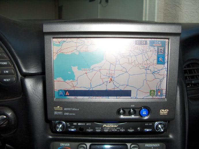
AVIC N1 Installation in a Corvette Convertible
This was the original Pioneer AVIC system and I think the latest version is the N3. there may be minor differences between versions. These instructions are offered in good faith. Please follow them only at your own discretion.
The initial impressions of the installation guide are daunting but in reality they are well written and easy to follow. By using a combination of the Pioneer instructions, the Soundgate instructions and these notes you should be OK.
Disconnect the car battery during installation. I used crimp type connectors to hook up to the existing wiring.
You will need a car stereo installation kit. I used the Metra Dashworks BB-444GM which I picked up from Best Buy.
The BOSE speakers on the Corvette require a specific installation harness. I used the Soundgate GMCRV1 (1.5DIN to 1 DIN) interface harness. Metra also make a suitable kit. The kit comes with comprehensive instructions which are Corvette specific.
You also need an antenna adaptor to take the GM small connector to a standard size, available from Autozone for a couple of $$.
You only need the system extension kit provided by Pioneer if you fit the mic system.
First step is to disassemble the console unit.
The instructions provided with the Soundgate harness also walk you through the process logically. These are reproduced below.
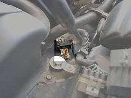
Next is to connect all the wires on the installation kit to the power cord provided by Pioneer. The wire colour match is good. I hooked up the power line to the main ignition switch by tapping into the power wire at that location. I subsequently had problems and eventually ran the power tap down to the spare yellow wire located in the passenger footwell. You could also use fuse #22 if you haven't used it already for something else. The main problem is finding a good earth. Eventually I took earth wires through the bulkhead in the passenger wheel well to the main earth point aft of the headlights. The earthing point (Ground Distribution Cell 14) is on the driver side, seen below . Remove the 10mm bolt and use a crimp-type ring-shaped terminal connector to secure the ground to the bolt. You may also want to solder the end, heat shrink it, and tape it.
The illumination wire can be connected at the hatch release fog light switch. If your car is an automatic, a connection could also be made at the gear indicator lights.
Next, drop the wires into the dash and route the bundles down to the glove box area. It takes some time to feed the wires down. Before installing the head unit you need to set the impedance on the rotary selector on the harness. This is a one off adjustment to personal taste.
The head unit mounts into the car using the GM specific car stereo installation kit. The housing supplied with the N1 fits into the installation kit. You may have to cut out small pieces of the aluminium structure of the dash at the rear of the radio to make the unit fit properly. It’s a fiddly install and the screws provided by Pioneer to mount the radio into its housing are tiny! I found I had to make adjustments to allow the radio housing to fit past the bolt heads provided with the installation kit. Once the housing is in the kit, it’s an easy fit into the dash with a couple of screws. Fit the installation kit first, connect the harness and AV lead and then feed in the head unit being careful to ease the wiring bundle into place and not trap wires. Struggle for a few minutes with the tiny screws being careful not to strip the threads.
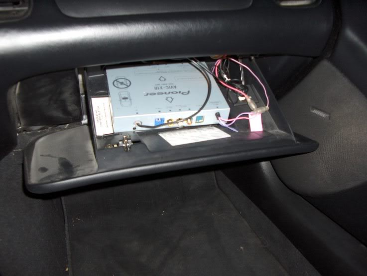
I looked at various alternatives for the hideaway box. It needs to sit flat and the orientation is critical (marked on the unit). It would not fit in the dash space without rearranging the order of the units (radio, A/C unit and ashtray). The preferred location would have been under the passenger seat but the routing for the wires was complex. I opted for the glove box. It takes away glove box space but the owners manual still fits below the unit. The wires feed in easily through a gap at the back of the glove box. Once the wires are all routed correctly, hook them up to the hideaway.
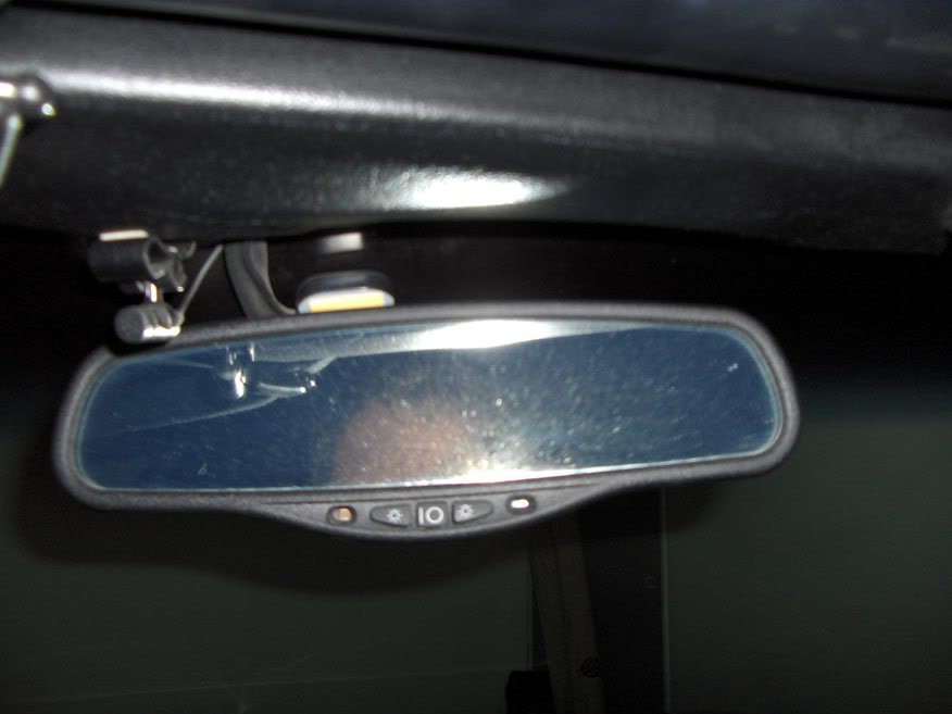
I mounted the GPS antenna on top of the rear view mirror and ran the wires around the top bar of the windscreen. The installation instructions stress that you need the metal plate (supplied by Pioneer) to ensure adequate GPS sensitivity. I didn’t use this plate and have had no problems so far. Accuracy seems good without it and the installation is much neater.
I routed the reverse wire around the back of the glove box, up through the door post, along the door sill and up the rear door post, around the convertible top housing and through the rear side wall of the boot behind the carpet. I then drilled a small hole through the bulkhead into the rear bumper area and fed the wire through. To attach to the reversing light circuit you need to remove the number plate housing. The screws are obvious.
The most complex hook up is the VSS wire. The PCM is inside the passenger wheel well and you may need to jack up the car to access it. I managed by turning the wheel fully to the left. The access panel to the PCM needs to be removed. Make sure to remove the three screws underneath the car that are partially hidden from view.
Below is a picture of the PCM. You will have to lie on your back and slide under the car to see this. PCM 2 is closest to you. On the 2000 Corvettes and up PCM, the VSS wire is c2 pin 50 and it is a green/white wire. You can see the pin number by squeezing the end of the grey cover and releasing the clip and moving the cover to the side. I used a crimp type connector to splice into this wire.
I've since heard that you can tap into the VSS wire in the instrument panel area. Worth a search because if you can get to it there and are confident you have the correct wire, the installation will be much easier.
The parking wire should be connected to the power side of the parking brake circuit. To view DVDs on the move (a dumb idea!) or operate the nav kit rerouting function while driving (actually often quite important and straight forward), instead of hooking the wire to the parking brake as instructed, attach it to earth. This will not work on the N2 and N3. However, you can achieve the same effect on the move by clicking the parking brake on a couple of notches. This earths the circuit without bring on the brake. You can then make changes on the move.
Reinstall the console and reconnect the battery.
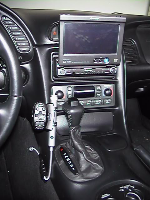
The finished Installation:
This was the original Pioneer AVIC system and I think the latest version is the N3. there may be minor differences between versions. These instructions are offered in good faith. Please follow them only at your own discretion.
The initial impressions of the installation guide are daunting but in reality they are well written and easy to follow. By using a combination of the Pioneer instructions, the Soundgate instructions and these notes you should be OK.
Disconnect the car battery during installation. I used crimp type connectors to hook up to the existing wiring.
You will need a car stereo installation kit. I used the Metra Dashworks BB-444GM which I picked up from Best Buy.
The BOSE speakers on the Corvette require a specific installation harness. I used the Soundgate GMCRV1 (1.5DIN to 1 DIN) interface harness. Metra also make a suitable kit. The kit comes with comprehensive instructions which are Corvette specific.
You also need an antenna adaptor to take the GM small connector to a standard size, available from Autozone for a couple of $$.
You only need the system extension kit provided by Pioneer if you fit the mic system.
First step is to disassemble the console unit.
The instructions provided with the Soundgate harness also walk you through the process logically. These are reproduced below.
Next is to connect all the wires on the installation kit to the power cord provided by Pioneer. The wire colour match is good. I hooked up the power line to the main ignition switch by tapping into the power wire at that location. I subsequently had problems and eventually ran the power tap down to the spare yellow wire located in the passenger footwell. You could also use fuse #22 if you haven't used it already for something else. The main problem is finding a good earth. Eventually I took earth wires through the bulkhead in the passenger wheel well to the main earth point aft of the headlights. The earthing point (Ground Distribution Cell 14) is on the driver side, seen below . Remove the 10mm bolt and use a crimp-type ring-shaped terminal connector to secure the ground to the bolt. You may also want to solder the end, heat shrink it, and tape it.
The illumination wire can be connected at the hatch release fog light switch. If your car is an automatic, a connection could also be made at the gear indicator lights.
Next, drop the wires into the dash and route the bundles down to the glove box area. It takes some time to feed the wires down. Before installing the head unit you need to set the impedance on the rotary selector on the harness. This is a one off adjustment to personal taste.
The head unit mounts into the car using the GM specific car stereo installation kit. The housing supplied with the N1 fits into the installation kit. You may have to cut out small pieces of the aluminium structure of the dash at the rear of the radio to make the unit fit properly. It’s a fiddly install and the screws provided by Pioneer to mount the radio into its housing are tiny! I found I had to make adjustments to allow the radio housing to fit past the bolt heads provided with the installation kit. Once the housing is in the kit, it’s an easy fit into the dash with a couple of screws. Fit the installation kit first, connect the harness and AV lead and then feed in the head unit being careful to ease the wiring bundle into place and not trap wires. Struggle for a few minutes with the tiny screws being careful not to strip the threads.
I looked at various alternatives for the hideaway box. It needs to sit flat and the orientation is critical (marked on the unit). It would not fit in the dash space without rearranging the order of the units (radio, A/C unit and ashtray). The preferred location would have been under the passenger seat but the routing for the wires was complex. I opted for the glove box. It takes away glove box space but the owners manual still fits below the unit. The wires feed in easily through a gap at the back of the glove box. Once the wires are all routed correctly, hook them up to the hideaway.
I mounted the GPS antenna on top of the rear view mirror and ran the wires around the top bar of the windscreen. The installation instructions stress that you need the metal plate (supplied by Pioneer) to ensure adequate GPS sensitivity. I didn’t use this plate and have had no problems so far. Accuracy seems good without it and the installation is much neater.
I routed the reverse wire around the back of the glove box, up through the door post, along the door sill and up the rear door post, around the convertible top housing and through the rear side wall of the boot behind the carpet. I then drilled a small hole through the bulkhead into the rear bumper area and fed the wire through. To attach to the reversing light circuit you need to remove the number plate housing. The screws are obvious.
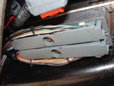
The most complex hook up is the VSS wire. The PCM is inside the passenger wheel well and you may need to jack up the car to access it. I managed by turning the wheel fully to the left. The access panel to the PCM needs to be removed. Make sure to remove the three screws underneath the car that are partially hidden from view.
Below is a picture of the PCM. You will have to lie on your back and slide under the car to see this. PCM 2 is closest to you. On the 2000 Corvettes and up PCM, the VSS wire is c2 pin 50 and it is a green/white wire. You can see the pin number by squeezing the end of the grey cover and releasing the clip and moving the cover to the side. I used a crimp type connector to splice into this wire.
I've since heard that you can tap into the VSS wire in the instrument panel area. Worth a search because if you can get to it there and are confident you have the correct wire, the installation will be much easier.
The parking wire should be connected to the power side of the parking brake circuit. To view DVDs on the move (a dumb idea!) or operate the nav kit rerouting function while driving (actually often quite important and straight forward), instead of hooking the wire to the parking brake as instructed, attach it to earth. This will not work on the N2 and N3. However, you can achieve the same effect on the move by clicking the parking brake on a couple of notches. This earths the circuit without bring on the brake. You can then make changes on the move.
Reinstall the console and reconnect the battery.
The finished Installation:
Last edited by pewter99; 03-19-2018 at 12:46 PM.
09-23-2007, 04:27 PM
#18
Burning Brakes


http://www.c5forum.com/diy/electro_mirror.php
or
http://forums.corvetteforum.com/show...post1562691970
or
http://forums.corvetteforum.com/show...post1562691970
Last edited by pewter99; 11-10-2007 at 04:02 PM.
09-23-2007, 04:37 PM
#19
Burning Brakes
http://forums.corvetteforum.com/show...HVAC+Light+fix
Note: there are more than 1 versions of the boards, read through the whole thread. Mine is like the one in post 50 in the above thread.
Note: there are more than 1 versions of the boards, read through the whole thread. Mine is like the one in post 50 in the above thread.
Last edited by white90conv; 09-23-2007 at 04:39 PM. Reason: additional information