
Output Shaft Install - Left and Right
 03-12-2010, 06:58 PM
#1
Burning Brakes

Thread Starter
So I finally got around to doing this  . I've read many, many threads about how weak the factory C5 LH output shaft is, and decided to replace it before it finally gave me a bad day. After much research, I decided to install the redesigned C6 Z06 shafts, both left and right. These are reputed to be very strong pieces, and at my power level, it doesn't sound like I'll be able to break them. I wouldn't break aftermarket 300M hardened shafts either, and would pay six times more for the privilage. GM removed various undercuts applied to the original C5 pieces and from what I've read, also changed the grade of steel that they're made from. That's why I decided to change out both. Relpacing the troublesome LH shaft is totally doable for a mechanically inclined person...so is the RH shaft, but it requires a press and one special tool.
More info on these diffs and the special tools needed to work on them is available here:
http://forums.corvetteforum.com/c5-t...ld-how-to.html
Be warned...this write-up is WAY LONGER than I thought it would be...
Here's what I did...
This is what I ordered from Gene Culley at http://www.gmpartshouseusa.com. This guy will bend over backwards to figure out what you're talking about and get the parts you need. Shipped straight to my door, taxes/shipping in, for less than 1/2 what the local dealer wanted before tax.
Part #s and prices are as follows:
LH C6 Z06 output shaft: 89060119 $57.41
RH C6 Z06 output shaft: 89060120 $38.19
RH C6 Z06 Side gear: 19180962 $76.00
RH C6 Z06 Side gear retaining ring: 12458084 $5.46
2 Axle Seals: 88996703 $18.24/each
2 Side Cover O-Rings: 89047953 $21.22/each
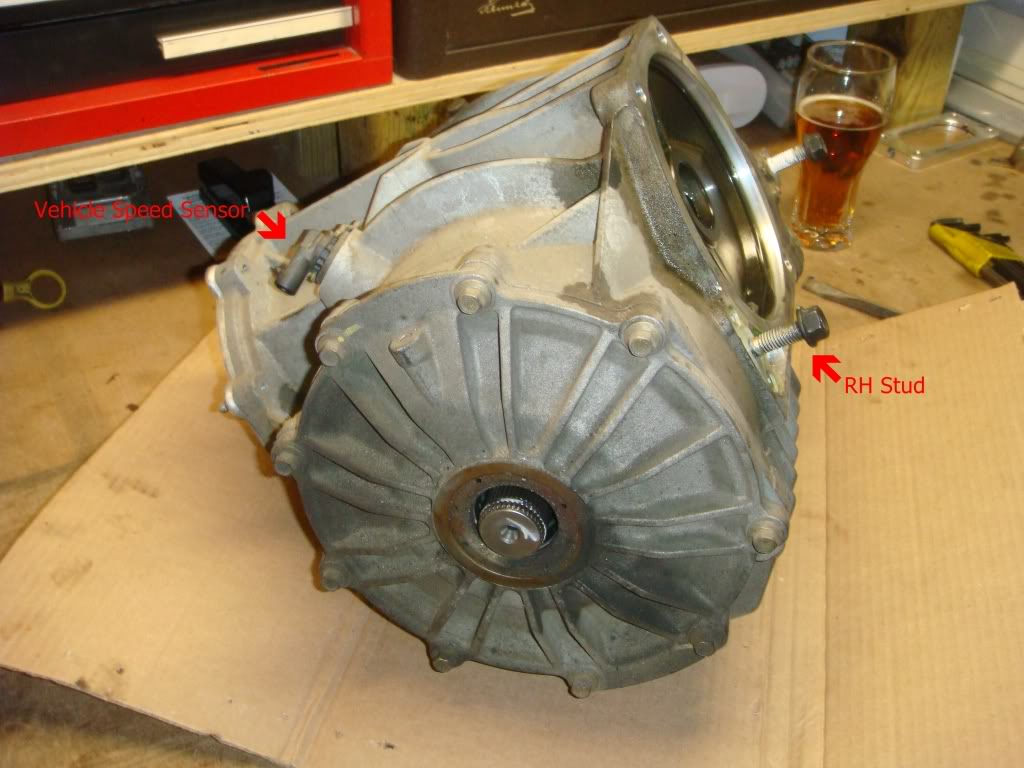
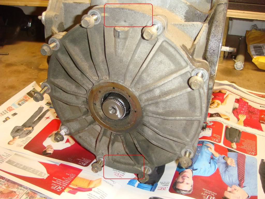
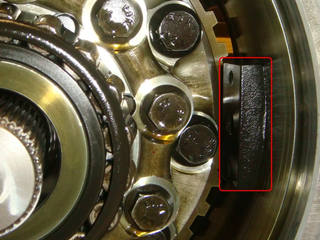
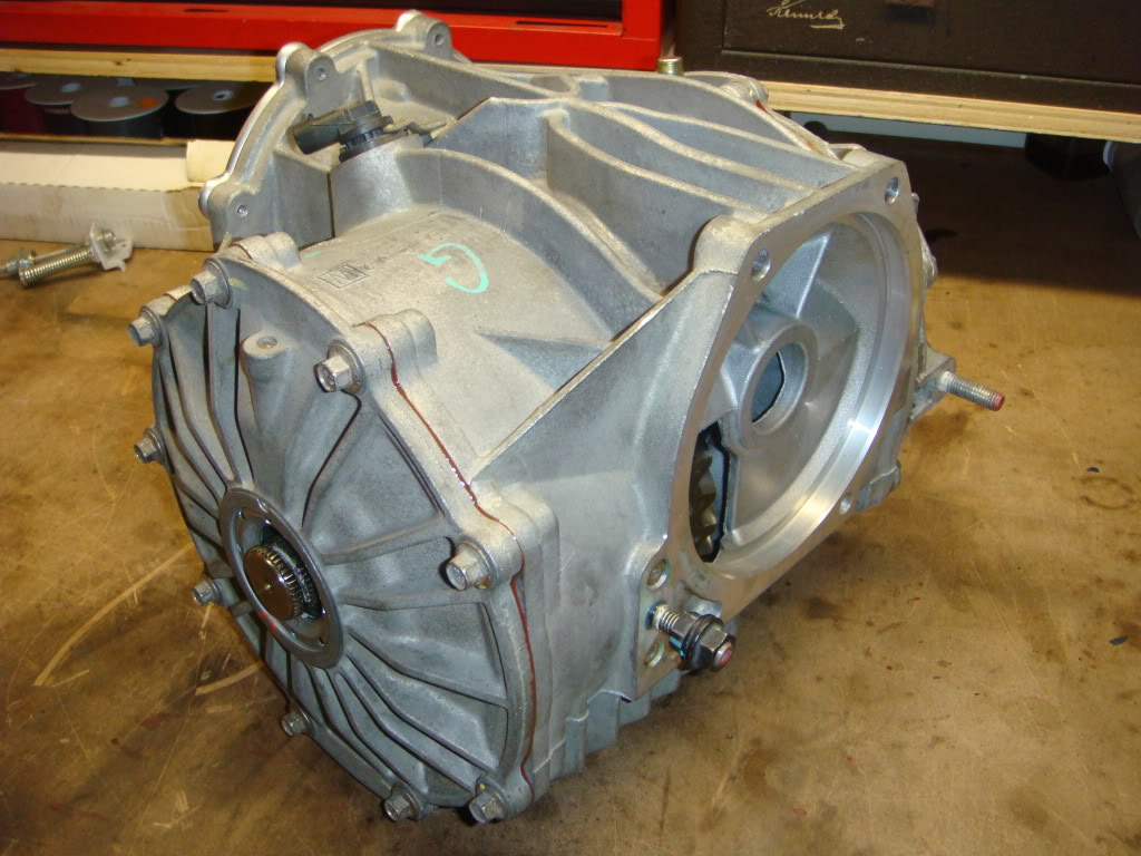
This install begins here. There are plenty of write-ups dealing with removing the differential from the vehicle. I pulled the entire driveline out, so that probably wouldn't apply to most people doing this anyway. Just make sure the oil is drained by the time it hits ur bench . Shown here is a RH view of the diff, with the tranny mounting face(front) on the right. Note the stud in the picture...it's the first thing that needs to be removed.
This stud threads into a steel block inside the case which also has to be removed to allow for complete disassembly of the diff. Probably the best way to remove this stud is by threading both nuts on, and tightening them into each other. Unscrew the stud using the inner nut. Don't use vice-grips, or you'll chew it up.
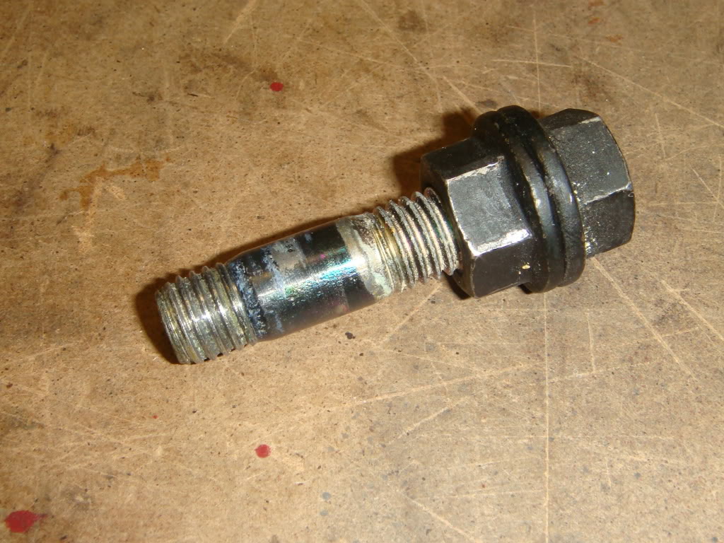
Here it is. Leave the nuts locked on...you'll need them again when you re-install the stud.
The next step is to remove the passenger side(RH) cover. Remove the nine 8mm bolts holding it to the case. The outlines show two webbed areas cast into the cover that can be tapped against to pop the cover free...
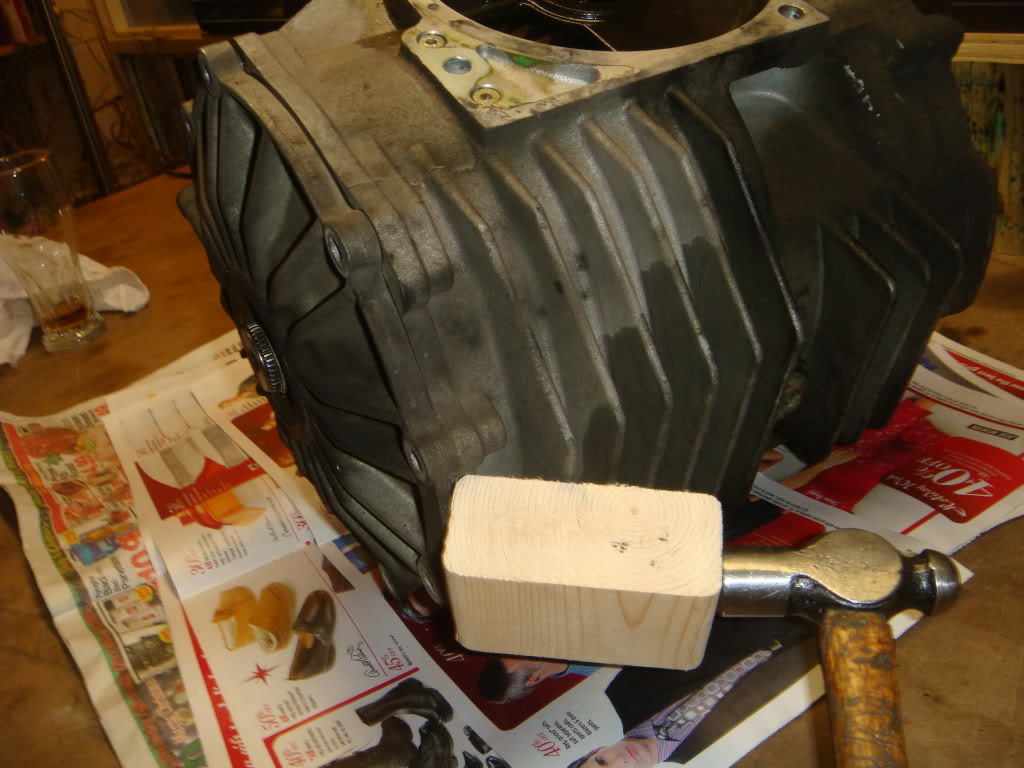
...like this. At this point, it's only the o-ring holding the cover in place. Be carefull...when the cover pops off, there's still gonna be oil.
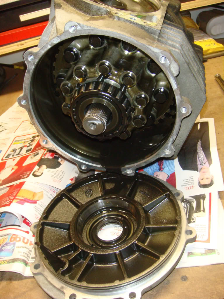
Removing the cover exposes the differential unit.
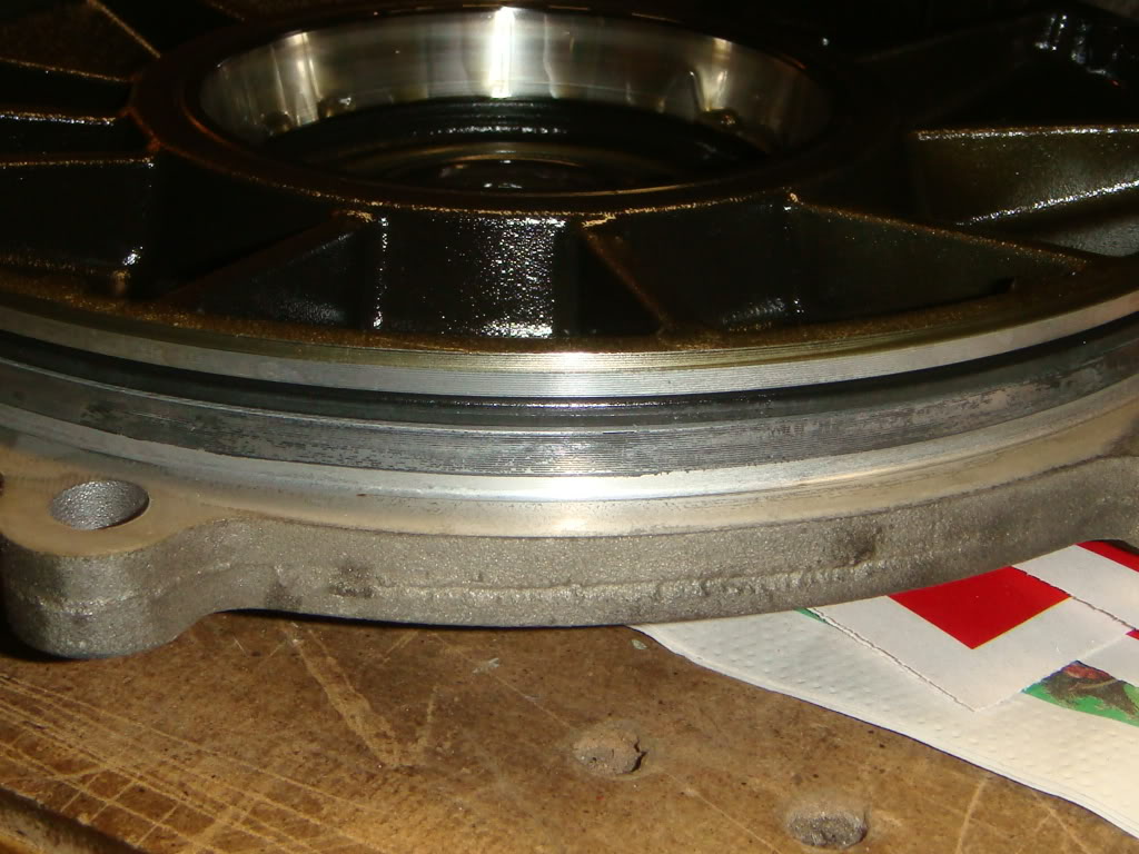
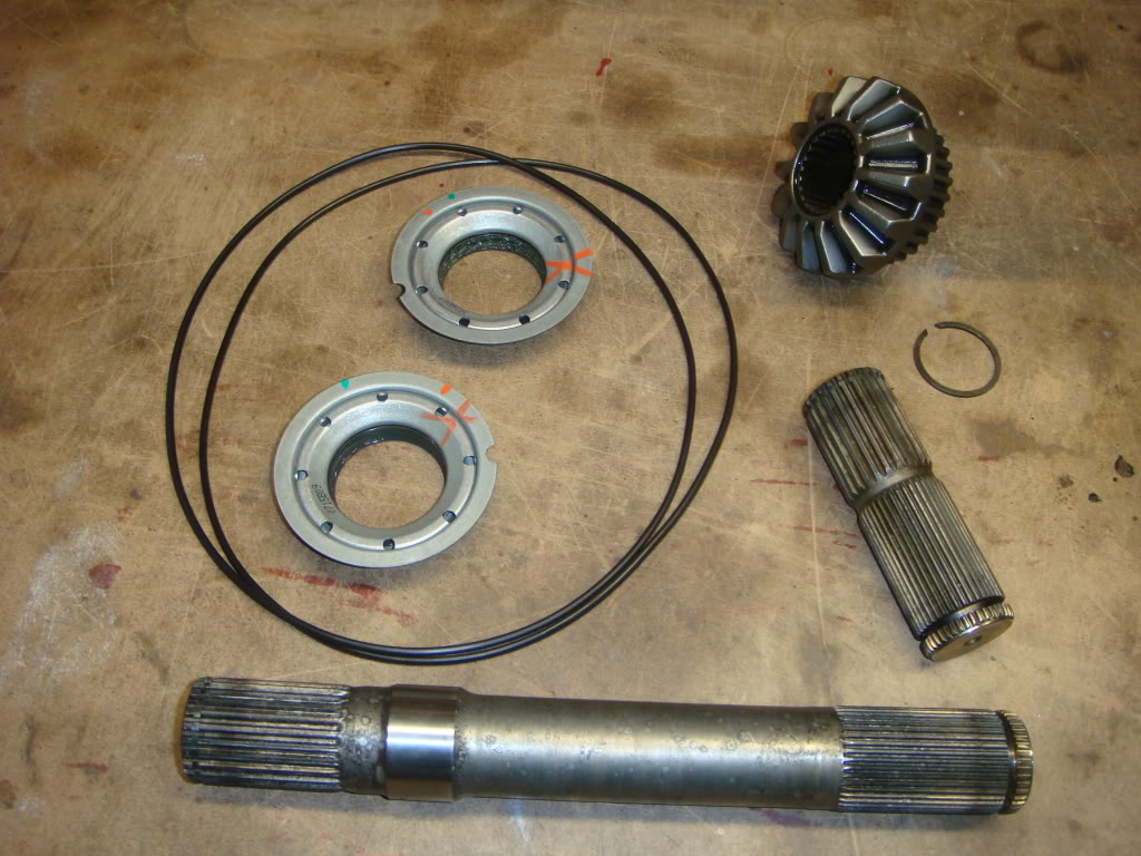
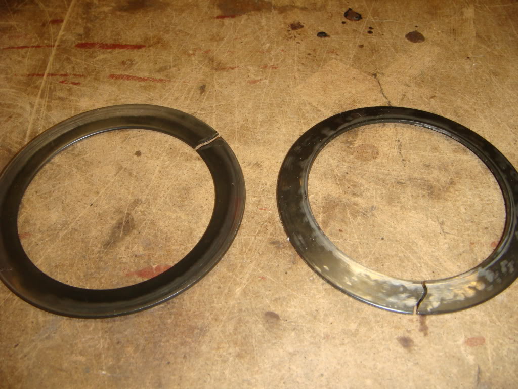
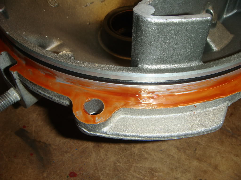
Here's a close-up of the huge o-ring which seals the cover to the case. The LH cover has one as well. Change them both upon re-assembly...just think of the work it took to get them laying on your bench like this.
This block is what the stud screwed into. It adds reinforcement to the stud mounting. Before the differential assembly can be pulled out, this block needs to be removed. Its held in position by two 6mm hex head screws from outside, one above and one below the stud. You"ll need a 4 mm allen key to remove them. Take note of the orientation of the block...thick side up.
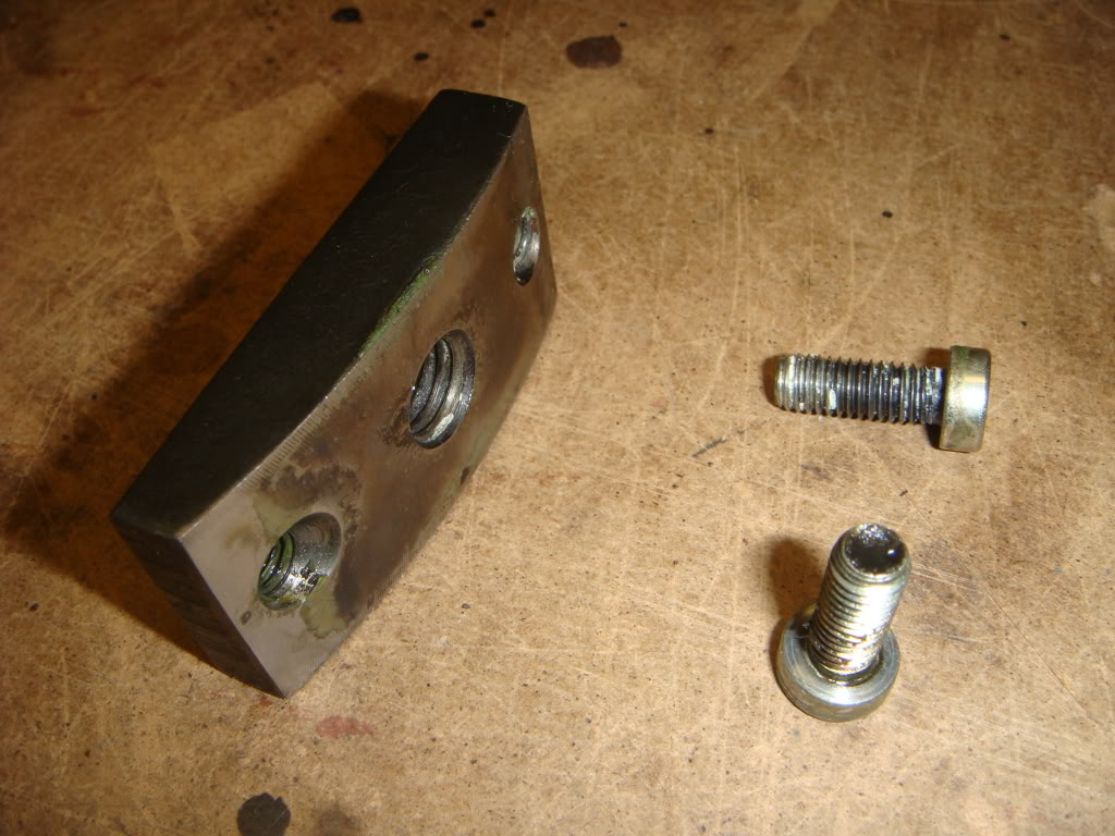
A close-up of the threaded stud block. Check out all the factory applied thread lock...I have a hard time imagining both those screws and the stud coming loose at the same time, but I guess GM didn't. I'll apply blue loc-tite here when this goes back together.
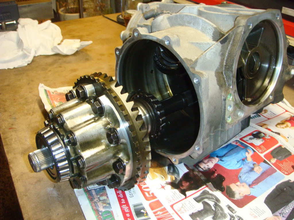
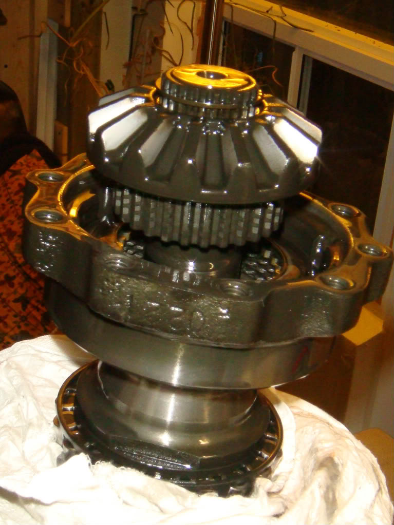
Once that block is removed, the entire differential unit can be pulled straight out of the case.
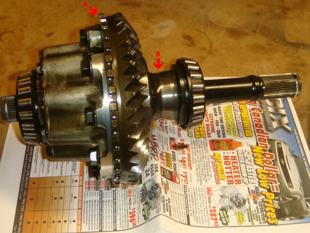
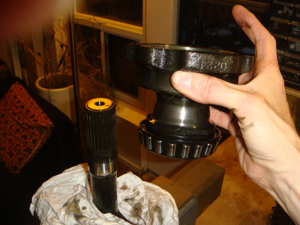
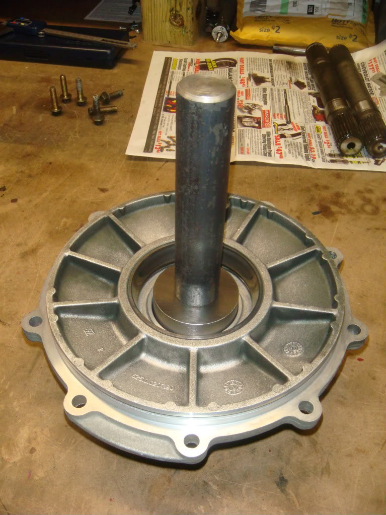
Aside from replacing the axle seals later, this is where the rest of our attention will go. The LH shaft is the long one on the right , and the shorter, optional replacment, RH shaft is just visible on the far left. Arrow "A" indicates the sensor teeth machined into the ring gear that the VSS uses to figure out how fast the car is going. Arrow "B" indicates the relief which allows the tranny output shaft to pass on its way to the rear mounted pinion. If you have any ideas about doing this *without* removing the differential from the car, pay attention to this pic!
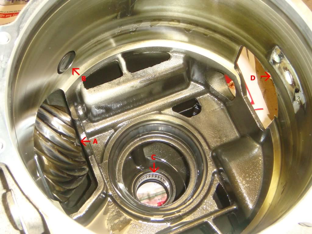
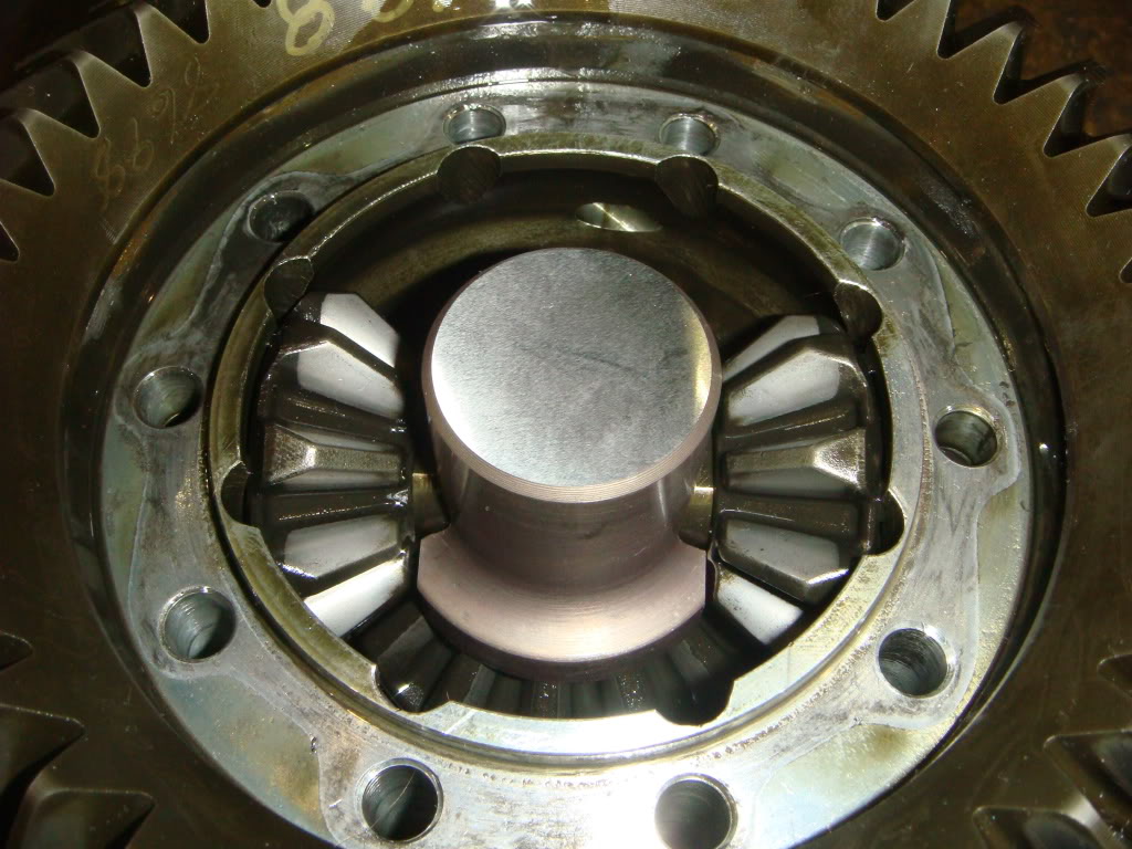
Looking down into the gutted case. Arrow "A" is the unusual rear mounted pinion. The round hole on the opposite side of the case is where the tranny output shaft enters the diff case on its way to the pinion. "B" is the sensing face of the VSS. "C" is the needle bearing used to support the driver-side inner CV joint. "D" is where the stud block lives.
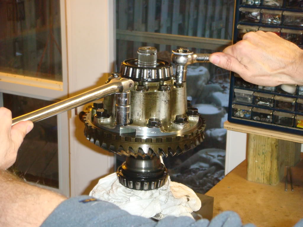
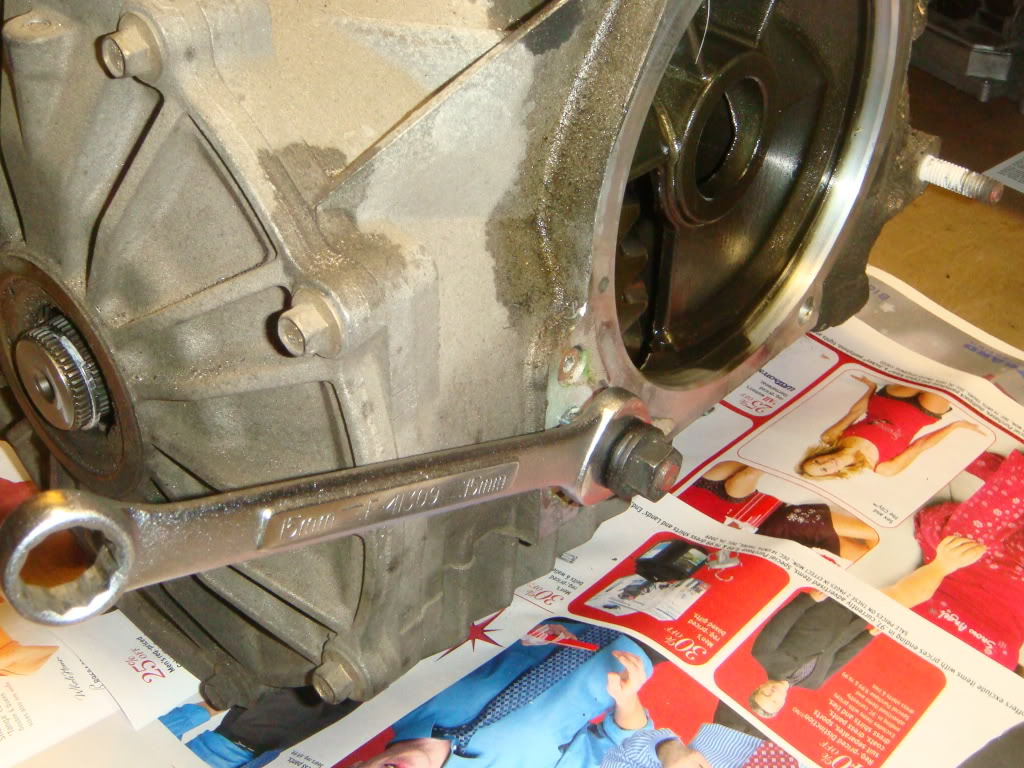
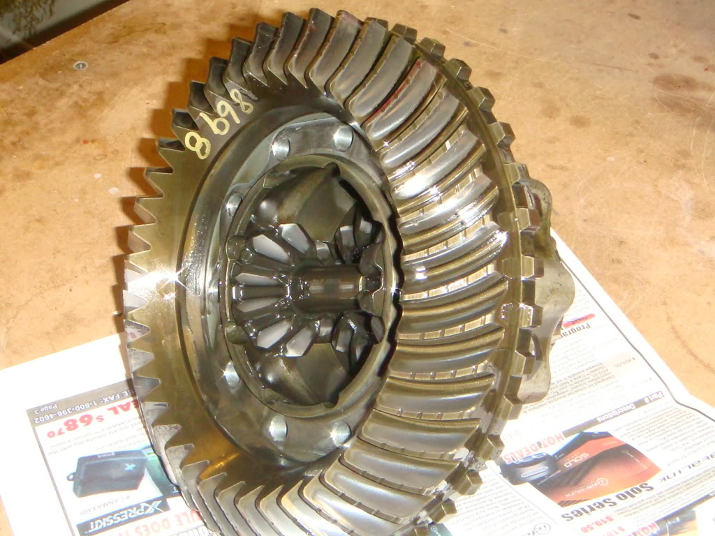
The differential assembly is made up of two halves, which now need to be split apart. I held the entire assembly in my bench vice by the longer LH shaft. I used copper jaws and a rag to prevent damage to the shaft that is about to go into the garbage. The bolts that need to be removed are the upper, smaller set. Why do they call it a "limited slip" differential? Try loosening one of these bolts with a wrench... Using another wrench on one of the larger ring gear bolts as shown will make it a "no slip" diff.
Leave two or three screws partially in. The differential can be split in half by tapping down on these screws...
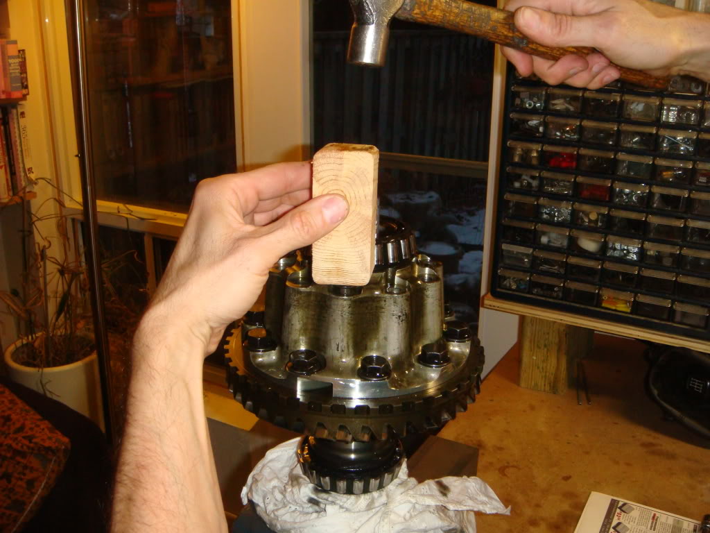
...Like this.
When the two halves seperate, the lower, LH portion will plop down like this...
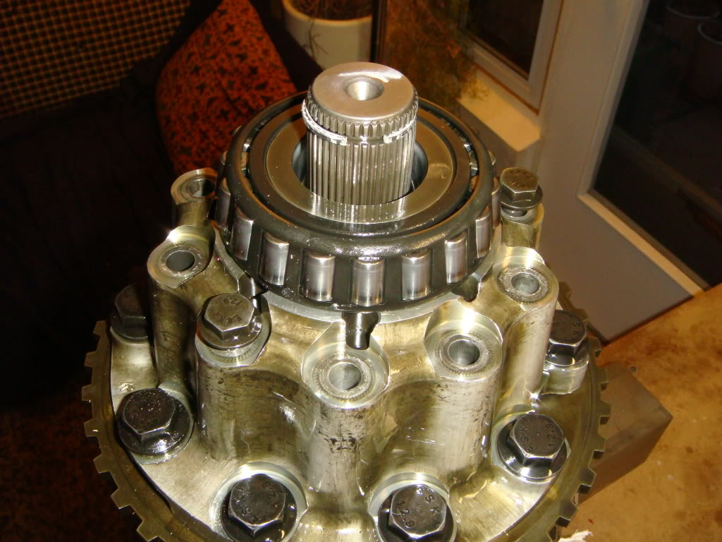
...and the upper, RH side will lift straight off. If you're only replacing the longer LH shaft, put this piece off to one side until you're ready to re-assemble.
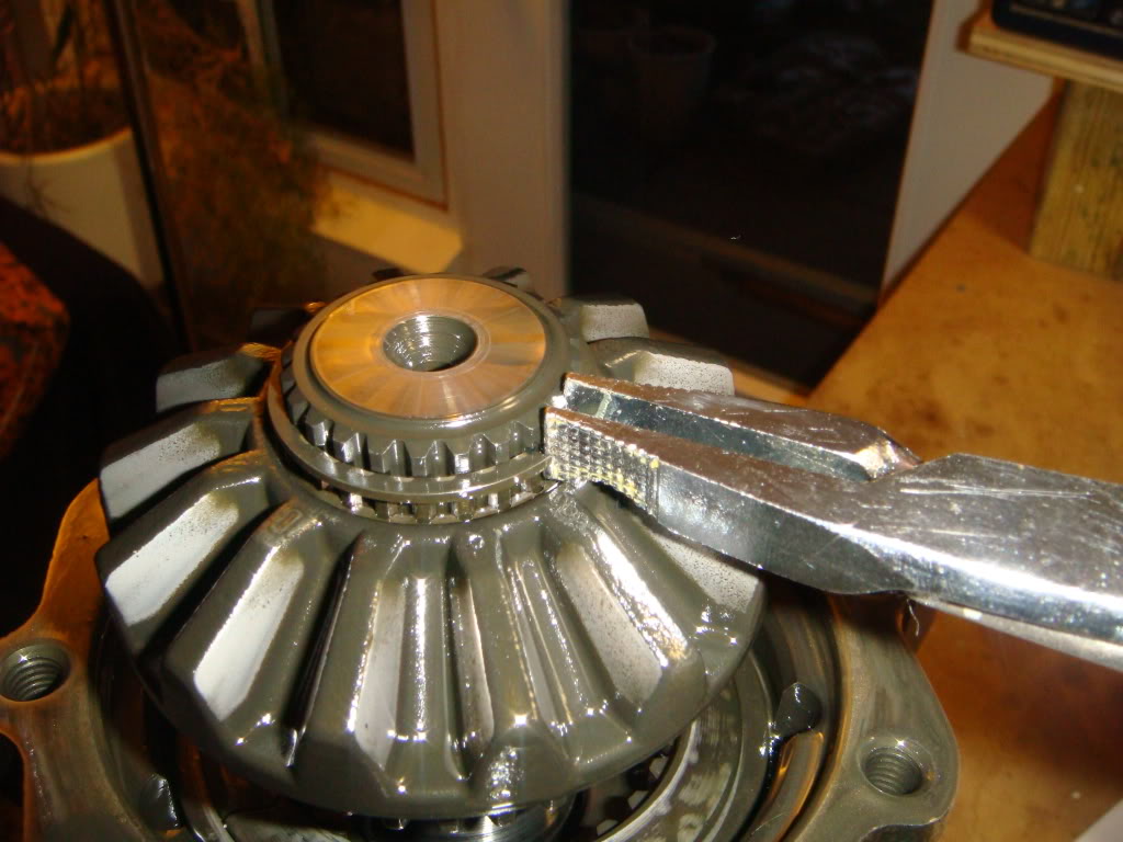
The next three steps cover the final removal of the LH output shaft. From this point on, it's very simple. First, remove the snap ring on the inner end of the shaft...
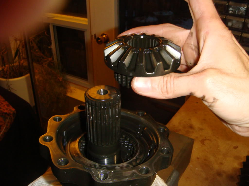
...and pull the side gear straight up and out.
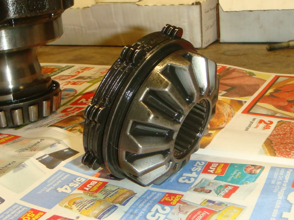
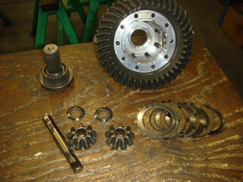
Finally, lift the remaining housing off the shaft. If you look down into the housing where the gear was, you'll see one of the two clutch packs this diff uses...make sure the disks don't fall out! If you remove them, make sure they go back in in the same order. The shaft is now out.
At this point, it would be a good idea to take a close look at the belleville washer that actually pre-loads the clutch pack. The OEM pieces are pure junk. Both of mine were cracked, and I bet both of yours are too. If these break, the clutches will begin to slip, shedding metallic crap into the unfiltered oil. A simple part like this can take out the entire diff if you're unlucky. To the best of my knowledge, GM doesn't service these parts seperately, so you have to look elsewhere. I went with the springs supplied by DTE. They're pretty expensive, but worth it if they eliminate unnecessary clutch slippage. Here's what DTE has to say about their product:
Engineered Features of This Product:
-Manufactured of high strength tool steel w/ high carbon-high chromium content
-Forged to increase hardness and material density
-Extremely wear resistant (approx. double that of O.E.)
-Maintains its clamping load force over a greater installed height spread
-No distortion w/ high heat applications
-Temperature resistance of up to 1875* F
-Provides 34% more clutch pack clamping load over O.E. application
-Quiet operation on turns
-Provides increased posi traction operation and clutch pack life
To install the new shaft, first replace the side gear into the housing. I've found that the easiest way to do this is to slide the clutch plates onto the gear first, then slide the whole thing back into the case. Ensure that the gear engages all the clutch disks and bottoms on the belleville washer. Poke the new shaft in from below, and put the snap ring back on. Don't forget to swap the CV joint retaining ring from the old shaft to the new! If the original RH shaft is staying in, lower the RH half of the diff back on and screw the unit back together. Torque to 41 lb/ft
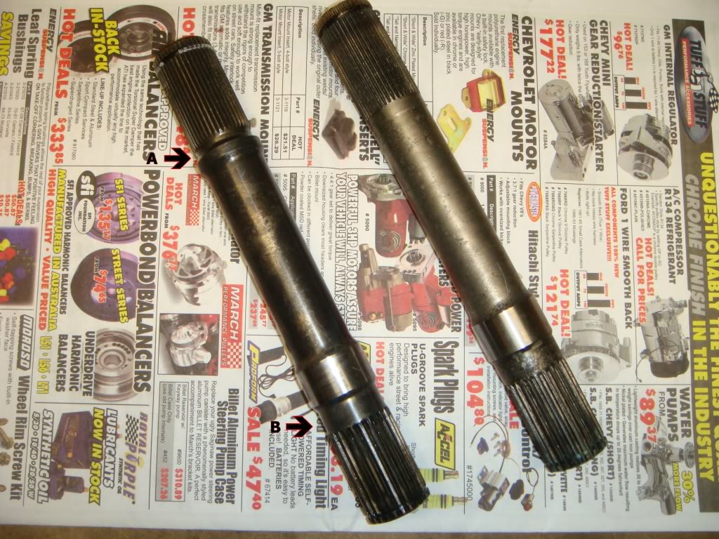
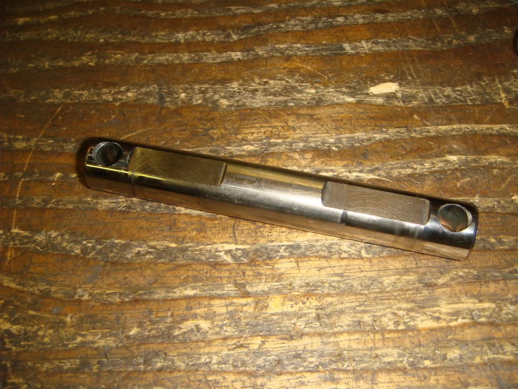
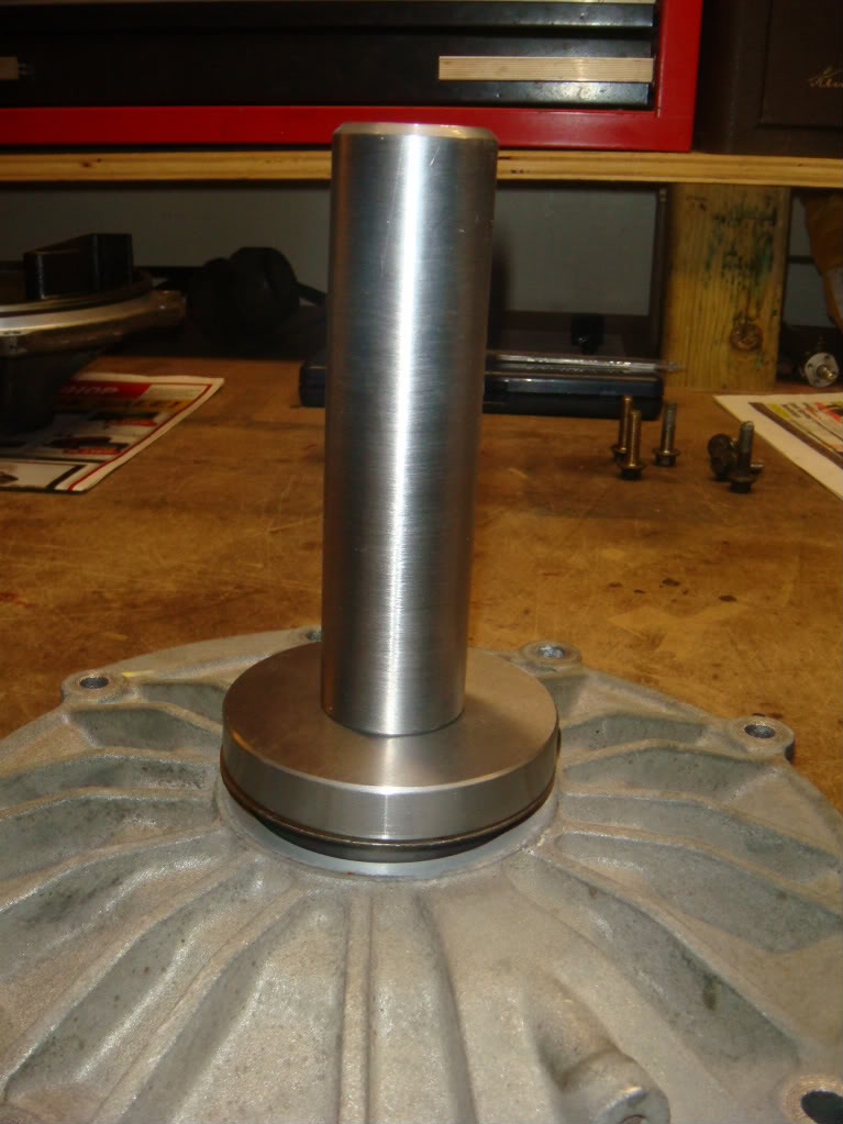
Here is a quick comparison between the original C5 shaft on the left and the new C6 Z06 shaft on the right. Arrow A points to the strange undercut which leads to most of the failures of this shaft. This was eliminated on the new shaft...as well, the diameter at B was beefed up by about 10% . All other dimensions are the same. The next few steps cover the removal of the shorter RH shaft...
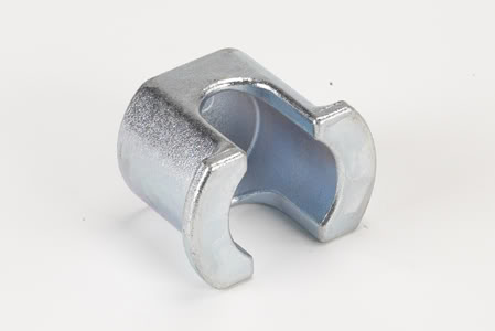
To remove shorty, you will need an arbor press and a special tool. GM specifies the use of Kent-Moore tool J-42162, something they call a differential side gear compressor. If you look into the RH half of the differential, you'll see two small spider gears on a shaft, with the side gear underneath. The RH shaft and side gear are one piece on the C5 and to remove this assembly, the cross-shaft has to come out. To do that, the side gear has to be pushed down to relieve spring pressure on the shaft. That's what this tool does. It's simply lowered down over the cross-shaft and rests on the side gear. You can then press against it to relieve the pressure. It costs about $80 bucks. Not the end of the world, I guess. I kept the 80 in my pocket and cobbled up my own.
Here's what I came up with...good enough! I've read of people using ball joint "pickle fork" seperators here as well. You don't need to get fancy...you just need to get around the cross shaft.
Here's the tool in position. Simply press down on it *slightly* with an arbor press to relieve pressure on the shaft, then slide the shaft with your finger. It's important to note that the differential case needs to be supported in the press by the case and not on the shaft sticking out the bottom, which will move down with the gear.
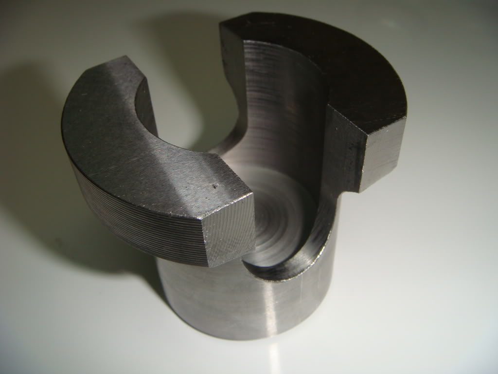
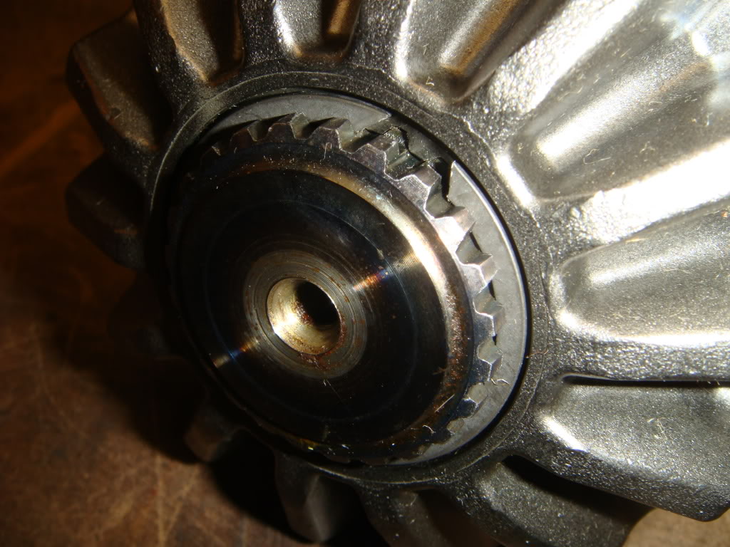
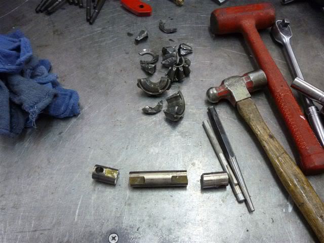
This is what will come out. Each spider gear has its own little washer that it rides against. Keep washers and gear pairs together. The RH output shaft/gear is at the upper left. Just as the left hand side, the belleville pre-load spring was broken.
This is a close-up of the cross shaft. When this is re-installed, the holes on either end must line up with the screw holes in the case. If they don't, you won't be able to insert those screws when the case halves are screwed back together. The best way to do this is actually slide a pair of screws in before releasing the press.
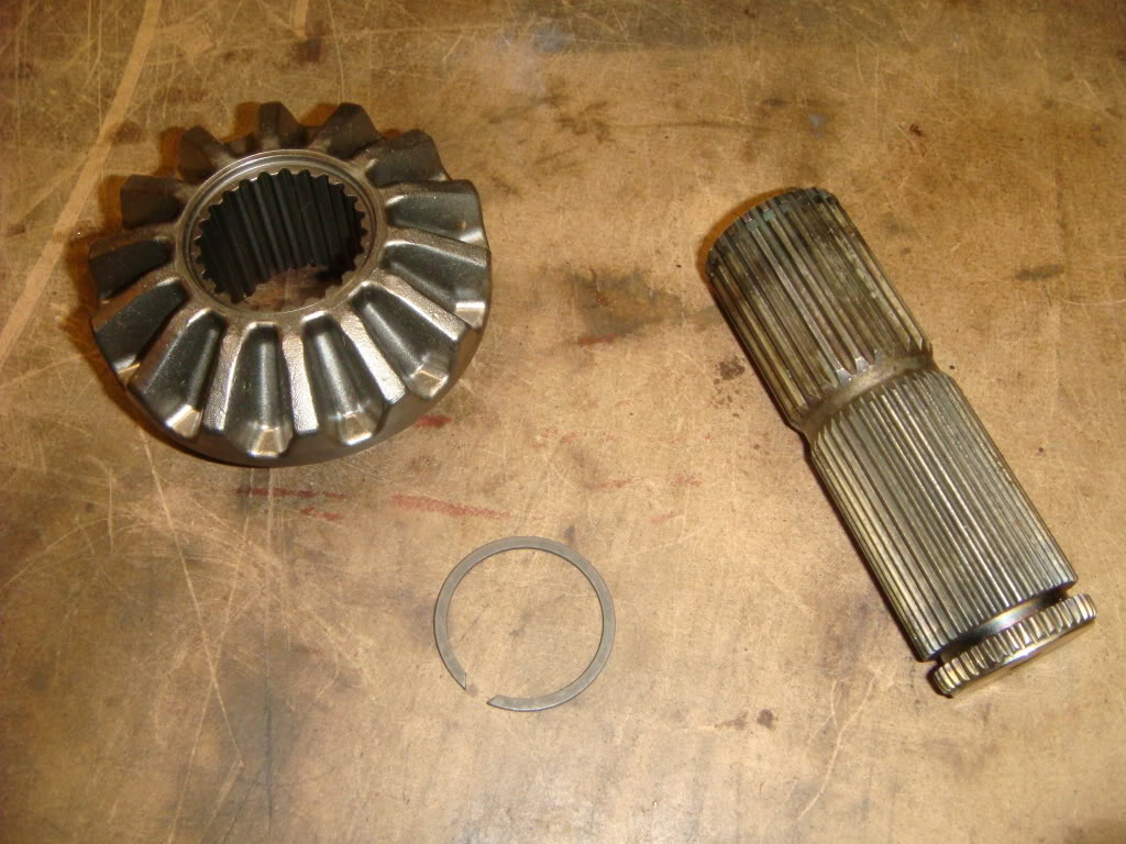
This is the C6 Z06 RH shaft assembly. The gear and shaft are two pieces, like the LH side. The gear has more meat on it, and the shaft is a uniform diameter straight across.
To Install, simply slide the shaft into the gear, and install the retaining ring. From this point, reassembly of the RH differential housing is just the opposite of dissassembly. Again, check the bellville washer. If you replaced the LH washer, obviously replace this one as well. Also, don't forget to move the CV joint retaining ring from the old shaft to the new.
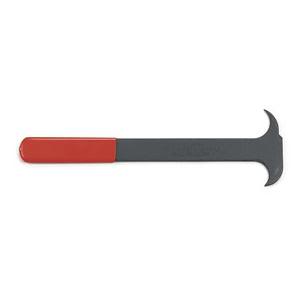
The last thing to do is replace the axle seals. Probably the best way to remove them is with a tool designed for the job, like this one from KD Tools. Otherwise, just pry them out carefully with a small screwdriver.
The RH seal can also be accessed from the back, so an appropriately sized bushing driver can also be used.
Install the seals either with a dedicated installation tool, or carefully tap it in with a hammer. The important thing is to make sure it goes in square and doesn't ****.
The last thing to do is apply a little sealer to the cover flanges. This, along with the o-rings, will all but ensure a leak free cover seal.
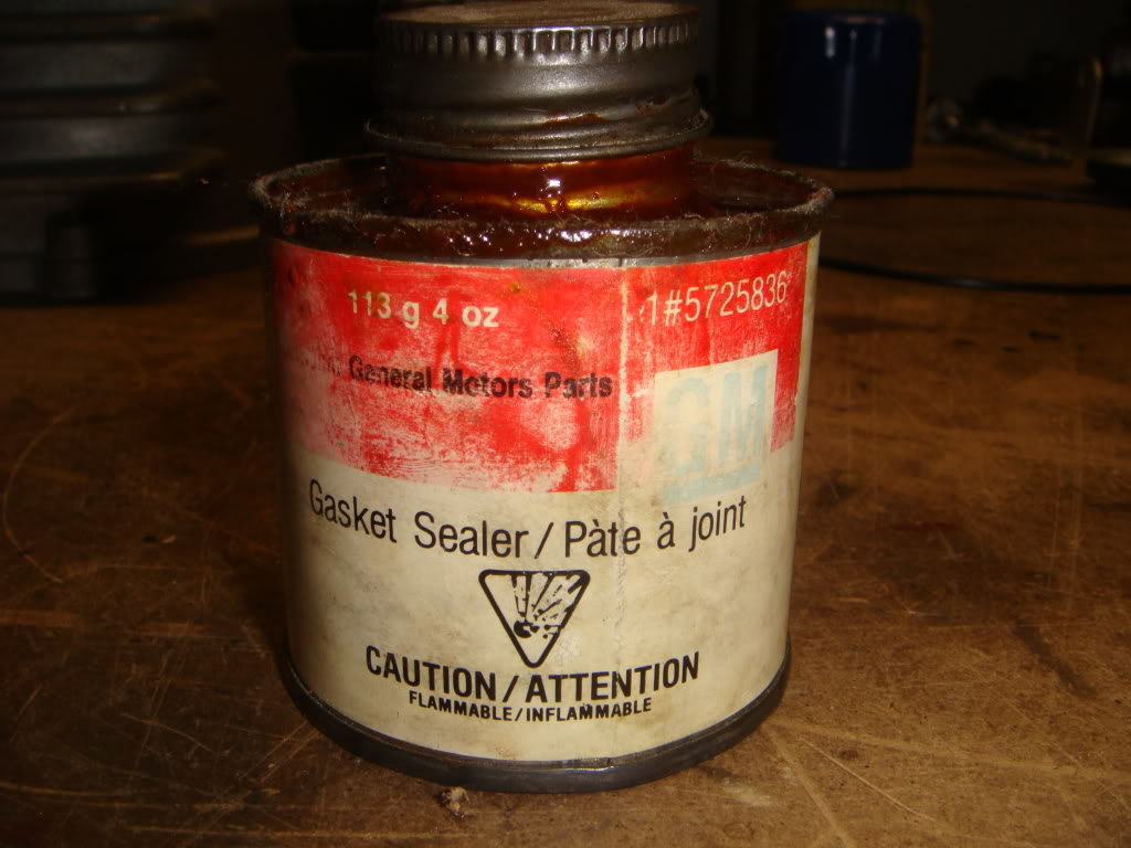
This is my weapon of choice for most sealing jobs. It's fairly thin, so it spreads easily into every nook, and it never dries. Permatex makes something similar called Aviation Sealant.
Heres hoping my car will move again.

FASTENER TIGHTENING SPECS
Left/Right Side Cover Bolts: 18 lb/ft
Stud Block Screws: 89 lb/in
Stud to stud block: 31 lb/ft
Differential Case Bolts: 41 lb/ft
. I've read many, many threads about how weak the factory C5 LH output shaft is, and decided to replace it before it finally gave me a bad day. After much research, I decided to install the redesigned C6 Z06 shafts, both left and right. These are reputed to be very strong pieces, and at my power level, it doesn't sound like I'll be able to break them. I wouldn't break aftermarket 300M hardened shafts either, and would pay six times more for the privilage. GM removed various undercuts applied to the original C5 pieces and from what I've read, also changed the grade of steel that they're made from. That's why I decided to change out both. Relpacing the troublesome LH shaft is totally doable for a mechanically inclined person...so is the RH shaft, but it requires a press and one special tool. More info on these diffs and the special tools needed to work on them is available here:
http://forums.corvetteforum.com/c5-t...ld-how-to.html
Be warned...this write-up is WAY LONGER than I thought it would be...
Here's what I did...
This is what I ordered from Gene Culley at http://www.gmpartshouseusa.com. This guy will bend over backwards to figure out what you're talking about and get the parts you need. Shipped straight to my door, taxes/shipping in, for less than 1/2 what the local dealer wanted before tax.
Part #s and prices are as follows:
LH C6 Z06 output shaft: 89060119 $57.41
RH C6 Z06 output shaft: 89060120 $38.19
RH C6 Z06 Side gear: 19180962 $76.00
RH C6 Z06 Side gear retaining ring: 12458084 $5.46
2 Axle Seals: 88996703 $18.24/each
2 Side Cover O-Rings: 89047953 $21.22/each
This install begins here. There are plenty of write-ups dealing with removing the differential from the vehicle. I pulled the entire driveline out, so that probably wouldn't apply to most people doing this anyway. Just make sure the oil is drained by the time it hits ur bench
. Shown here is a RH view of the diff, with the tranny mounting face(front) on the right. Note the stud in the picture...it's the first thing that needs to be removed.This stud threads into a steel block inside the case which also has to be removed to allow for complete disassembly of the diff. Probably the best way to remove this stud is by threading both nuts on, and tightening them into each other. Unscrew the stud using the inner nut. Don't use vice-grips, or you'll chew it up.
Here it is. Leave the nuts locked on...you'll need them again when you re-install the stud.
The next step is to remove the passenger side(RH) cover. Remove the nine 8mm bolts holding it to the case. The outlines show two webbed areas cast into the cover that can be tapped against to pop the cover free...
...like this. At this point, it's only the o-ring holding the cover in place. Be carefull...when the cover pops off, there's still gonna be oil.
Removing the cover exposes the differential unit.
Here's a close-up of the huge o-ring which seals the cover to the case. The LH cover has one as well. Change them both upon re-assembly...just think of the work it took to get them laying on your bench like this.
This block is what the stud screwed into. It adds reinforcement to the stud mounting. Before the differential assembly can be pulled out, this block needs to be removed. Its held in position by two 6mm hex head screws from outside, one above and one below the stud. You"ll need a 4 mm allen key to remove them. Take note of the orientation of the block...thick side up.
A close-up of the threaded stud block. Check out all the factory applied thread lock...I have a hard time imagining both those screws and the stud coming loose at the same time, but I guess GM didn't. I'll apply blue loc-tite here when this goes back together.
Once that block is removed, the entire differential unit can be pulled straight out of the case.
Aside from replacing the axle seals later, this is where the rest of our attention will go. The LH shaft is the long one on the right
, and the shorter, optional replacment, RH shaft is just visible on the far left. Arrow "A" indicates the sensor teeth machined into the ring gear that the VSS uses to figure out how fast the car is going. Arrow "B" indicates the relief which allows the tranny output shaft to pass on its way to the rear mounted pinion. If you have any ideas about doing this *without* removing the differential from the car, pay attention to this pic!Looking down into the gutted case. Arrow "A" is the unusual rear mounted pinion. The round hole on the opposite side of the case is where the tranny output shaft enters the diff case on its way to the pinion. "B" is the sensing face of the VSS. "C" is the needle bearing used to support the driver-side inner CV joint. "D" is where the stud block lives.
The differential assembly is made up of two halves, which now need to be split apart. I held the entire assembly in my bench vice by the longer LH shaft. I used copper jaws and a rag to prevent damage to the shaft that is about to go into the garbage. The bolts that need to be removed are the upper, smaller set. Why do they call it a "limited slip" differential? Try loosening one of these bolts with a wrench... Using another wrench on one of the larger ring gear bolts as shown will make it a "no slip" diff.
Leave two or three screws partially in. The differential can be split in half by tapping down on these screws...
...Like this.
When the two halves seperate, the lower, LH portion will plop down like this...
...and the upper, RH side will lift straight off. If you're only replacing the longer LH shaft, put this piece off to one side until you're ready to re-assemble.
The next three steps cover the final removal of the LH output shaft. From this point on, it's very simple. First, remove the snap ring on the inner end of the shaft...
...and pull the side gear straight up and out.
Finally, lift the remaining housing off the shaft. If you look down into the housing where the gear was, you'll see one of the two clutch packs this diff uses...make sure the disks don't fall out! If you remove them, make sure they go back in in the same order. The shaft is now out.
At this point, it would be a good idea to take a close look at the belleville washer that actually pre-loads the clutch pack. The OEM pieces are pure junk. Both of mine were cracked, and I bet both of yours are too. If these break, the clutches will begin to slip, shedding metallic crap into the unfiltered oil. A simple part like this can take out the entire diff if you're unlucky. To the best of my knowledge, GM doesn't service these parts seperately, so you have to look elsewhere. I went with the springs supplied by DTE. They're pretty expensive, but worth it if they eliminate unnecessary clutch slippage. Here's what DTE has to say about their product:
Engineered Features of This Product:
-Manufactured of high strength tool steel w/ high carbon-high chromium content
-Forged to increase hardness and material density
-Extremely wear resistant (approx. double that of O.E.)
-Maintains its clamping load force over a greater installed height spread
-No distortion w/ high heat applications
-Temperature resistance of up to 1875* F
-Provides 34% more clutch pack clamping load over O.E. application
-Quiet operation on turns
-Provides increased posi traction operation and clutch pack life
To install the new shaft, first replace the side gear into the housing. I've found that the easiest way to do this is to slide the clutch plates onto the gear first, then slide the whole thing back into the case. Ensure that the gear engages all the clutch disks and bottoms on the belleville washer. Poke the new shaft in from below, and put the snap ring back on. Don't forget to swap the CV joint retaining ring from the old shaft to the new! If the original RH shaft is staying in, lower the RH half of the diff back on and screw the unit back together. Torque to 41 lb/ft
Here is a quick comparison between the original C5 shaft on the left and the new C6 Z06 shaft on the right. Arrow A points to the strange undercut which leads to most of the failures of this shaft. This was eliminated on the new shaft...as well, the diameter at B was beefed up by about 10% . All other dimensions are the same. The next few steps cover the removal of the shorter RH shaft...
To remove shorty, you will need an arbor press and a special tool. GM specifies the use of Kent-Moore tool J-42162, something they call a differential side gear compressor. If you look into the RH half of the differential, you'll see two small spider gears on a shaft, with the side gear underneath. The RH shaft and side gear are one piece on the C5 and to remove this assembly, the cross-shaft has to come out. To do that, the side gear has to be pushed down to relieve spring pressure on the shaft. That's what this tool does. It's simply lowered down over the cross-shaft and rests on the side gear. You can then press against it to relieve the pressure. It costs about $80 bucks. Not the end of the world, I guess. I kept the 80 in my pocket and cobbled up my own.
Here's what I came up with...good enough! I've read of people using ball joint "pickle fork" seperators here as well. You don't need to get fancy...you just need to get around the cross shaft.
Here's the tool in position. Simply press down on it *slightly* with an arbor press to relieve pressure on the shaft, then slide the shaft with your finger. It's important to note that the differential case needs to be supported in the press by the case and not on the shaft sticking out the bottom, which will move down with the gear.
This is what will come out. Each spider gear has its own little washer that it rides against. Keep washers and gear pairs together. The RH output shaft/gear is at the upper left. Just as the left hand side, the belleville pre-load spring was broken.
This is a close-up of the cross shaft. When this is re-installed, the holes on either end must line up with the screw holes in the case. If they don't, you won't be able to insert those screws when the case halves are screwed back together. The best way to do this is actually slide a pair of screws in before releasing the press.
This is the C6 Z06 RH shaft assembly. The gear and shaft are two pieces, like the LH side. The gear has more meat on it, and the shaft is a uniform diameter straight across.
To Install, simply slide the shaft into the gear, and install the retaining ring. From this point, reassembly of the RH differential housing is just the opposite of dissassembly. Again, check the bellville washer. If you replaced the LH washer, obviously replace this one as well. Also, don't forget to move the CV joint retaining ring from the old shaft to the new.
The last thing to do is replace the axle seals. Probably the best way to remove them is with a tool designed for the job, like this one from KD Tools. Otherwise, just pry them out carefully with a small screwdriver.
The RH seal can also be accessed from the back, so an appropriately sized bushing driver can also be used.
Install the seals either with a dedicated installation tool, or carefully tap it in with a hammer. The important thing is to make sure it goes in square and doesn't ****.
The last thing to do is apply a little sealer to the cover flanges. This, along with the o-rings, will all but ensure a leak free cover seal.
This is my weapon of choice for most sealing jobs. It's fairly thin, so it spreads easily into every nook, and it never dries. Permatex makes something similar called Aviation Sealant.
Heres hoping my car will move again
.FASTENER TIGHTENING SPECS
Left/Right Side Cover Bolts: 18 lb/ft
Stud Block Screws: 89 lb/in
Stud to stud block: 31 lb/ft
Differential Case Bolts: 41 lb/ft
Last edited by Its_Go_Time; 01-12-2012 at 09:14 AM. Reason: Added link to more info
 03-12-2010, 09:01 PM
#2
Le Mans Master


Member Since: May 2007
Location: Belleville Mich.
Posts: 5,393
Likes: 0
Received 15 Likes
on
14 Posts

Great write up Tom, as usual excellent detail, photos and specifics. This is the way to go when wanting to go with the heavy duty shafts. While you're in there you might as well do the shorty too, as you described and to also change out the belleville washers, with the DTE's even if they're not broke, because it would just be a matter of time.
This write up will give me some incentive to grab my stock Z 3:42 off the shelf and give it a "special" heavy duty treatment. You're special to the Corvette Forum, and keep up the excellent write ups.
This write up will give me some incentive to grab my stock Z 3:42 off the shelf and give it a "special" heavy duty treatment. You're special to the Corvette Forum, and keep up the excellent write ups.
The following users liked this post:
Groffunitracing (01-26-2020)
03-12-2010, 09:16 PM
#3
Safety Car

Nice write up, and well documented with the pics! I find it hard to take pics as I go, would rather get the job over with. I like the first pic with your glass of brew. 
The cross pin gave me shivers. Look what happen to mine last year. This was due to hard launch on sticky tires. If you ever get a chance to do again, I believe RPM has an upgraded one you could pop in there, to keep this from happening.
The cross pin gave me shivers. Look what happen to mine last year. This was due to hard launch on sticky tires. If you ever get a chance to do again, I believe RPM has an upgraded one you could pop in there, to keep this from happening.
03-12-2010, 09:45 PM
#4
Tech Contributor
Member Since: Aug 1999
Location: Should this thoughtful, valuable contribution meet with no acknowledgement or 'thanks' this post----
Posts: 16,382
Received 399 Likes
on
257 Posts

Outstanding! Best I've seen as far as a writeup for this component. One question, I have a used 3:42 (non-Z06) I will install this summer...I don't race so won't be addressing the shafts, but I want to know which of those additional parts should I replace prior to assembly? Gene will get my order too...just need to get the right stuff...thanks

The following users liked this post:
hotfrank (07-30-2021)
03-13-2010, 02:19 AM
#6
Tech Contributor


Member Since: Dec 1999
Location: Anthony TX
Posts: 32,736
Received 2,180 Likes
on
1,583 Posts
CI 6,7,8,9,11 Vet
St. Jude Donor '08
Tommy
WOW! Your article / post came about JUST IN TIME!!! I am about to do the C6 ZO6 short and Long shaft swap!
THANK YOU for this fantastic write up!!! Very well written and illustrated!
I have a couple of questions:
1. Would it be worth it to change the clutches? I'm guessing my belleville washer/s are toast but, 60,000 miles, what do you think? I don't see any issues but, something to think about. Have no idea how long they normally last. Is there a minimum Clutch disk thickness that we can compare the used ones to?
2. Didn't know that the side gear needed to be up-graded. Ordered that also as well as the O rings and seals. Thanks for the heads up. Going to be contacting DTE for the washer and thanks to " Chris Stewart " the cross shaft! Any other DTE stuff while I'm putting that order together?????
3. When removing the cross shaft, approx how much force does it require to press the gear down to release the cross shaft? Wondering if I can do it without a press.
Thanks again for the very detailed and accurate write up! This post is a keeper!
Bill Curlee
WOW! Your article / post came about JUST IN TIME!!! I am about to do the C6 ZO6 short and Long shaft swap!
THANK YOU for this fantastic write up!!!
Very well written and illustrated! I have a couple of questions:
1. Would it be worth it to change the clutches? I'm guessing my belleville washer/s are toast but, 60,000 miles, what do you think? I don't see any issues but, something to think about. Have no idea how long they normally last. Is there a minimum Clutch disk thickness that we can compare the used ones to?
2. Didn't know that the side gear needed to be up-graded. Ordered that also as well as the O rings and seals. Thanks for the heads up. Going to be contacting DTE for the washer and thanks to " Chris Stewart " the cross shaft!
Any other DTE stuff while I'm putting that order together?????3. When removing the cross shaft, approx how much force does it require to press the gear down to release the cross shaft? Wondering if I can do it without a press.
Thanks again for the very detailed and accurate write up!
This post is a keeper!Bill Curlee
Last edited by Bill Curlee; 03-13-2010 at 03:05 AM.
03-13-2010, 11:35 AM
#7
Burning Brakes
Thread Starter
Thank you everyone for your kind words! Bumble-z Bob, are you trying to make me blush?:o
To anyone who wants to dig around inside and strengthen their differential, I would recommend checking out this post as well. The C6 Z06 diff has had a lot of improvements made to it which can be retrofitted into our units for not much money.
http://forums.corvetteforum.com/c5-g...-z06-guts.html
Obviously, if you're making *serious* power, this probably won't fly either...
 [/QUOTE]
^^ This sucks...the aluminum differential housing must have been annihilated! Just think, in an open diff, ALL the torque generated by the engine transfers to the side gears (wheels) through that shaft. With a limited slip like ours, there's a secondary path from the ring gear housing thru the clutches to the side gears. If the preload springs are shot, the clutches won't transfer much torque, placing more of the burden on that shaft.
Bill, The manual doesn't give any minimum thickness for the clutch disks. They just recommend a visual inspection to look for gouges or missing friction material. They also say to check for flatness and burn/overheating marks on the steels. The frictions look a lot like those you'd find in an auto tranny. They have little grooves in them to channel oil. Mine still had deep grooves, so I reused them. Gene wants about $110 for eack pack, so I decided to take a pass.
I half-heartedly tried to compress it by hand, and it didn't budge! Re-installing with the DTE springs would be even harder...it takes about 2 seconds to do with a press with no cussing or extra grey hairs to worry about.
To anyone who wants to dig around inside and strengthen their differential, I would recommend checking out this post as well. The C6 Z06 diff has had a lot of improvements made to it which can be retrofitted into our units for not much money.
http://forums.corvetteforum.com/c5-g...-z06-guts.html
Obviously, if you're making *serious* power, this probably won't fly either...
[/QUOTE]^^ This sucks...the aluminum differential housing must have been annihilated! Just think, in an open diff, ALL the torque generated by the engine transfers to the side gears (wheels) through that shaft. With a limited slip like ours, there's a secondary path from the ring gear housing thru the clutches to the side gears. If the preload springs are shot, the clutches won't transfer much torque, placing more of the burden on that shaft.
Bill, The manual doesn't give any minimum thickness for the clutch disks. They just recommend a visual inspection to look for gouges or missing friction material. They also say to check for flatness and burn/overheating marks on the steels. The frictions look a lot like those you'd find in an auto tranny. They have little grooves in them to channel oil. Mine still had deep grooves, so I reused them. Gene wants about $110 for eack pack, so I decided to take a pass.
I half-heartedly tried to compress it by hand, and it didn't budge! Re-installing with the DTE springs would be even harder...it takes about 2 seconds to do with a press with no cussing or extra grey hairs to worry about.
03-13-2010, 12:04 PM
#8
Le Mans Master
great write up!!!!!!
thanks for sharing and taking the time to do the write up...how much were the washers from dte?
how was the condition of the clutch packs?
thanks for sharing and taking the time to do the write up...how much were the washers from dte?
how was the condition of the clutch packs?
03-13-2010, 02:28 PM
#10
Tech Contributor
Member Since: Dec 1999
Location: Anthony TX
Posts: 32,736
Received 2,180 Likes
on
1,583 Posts
CI 6,7,8,9,11 Vet
St. Jude Donor '08
I have a press at work. Just wondering and you gave me all the answers I needed
Thanks again!
Bill
Thanks again!
Bill
03-13-2010, 05:25 PM
#11
Tech Contributor
Member Since: Aug 1999
Location: Should this thoughtful, valuable contribution meet with no acknowledgement or 'thanks' this post----
Posts: 16,382
Received 399 Likes
on
257 Posts
Outstanding! Best I've seen as far as a writeup for this component. One question, I have a used 3:42 (non-Z06) I will install this summer...I don't race so won't be addressing the shafts, but I want to know which of those additional parts should I replace prior to assembly? Gene will get my order too...just need to get the right stuff...thanks
03-13-2010, 05:43 PM
#12
Burning Brakes
Thread Starter
My apologies...I wasn't sure exactly what you were asking. As I mentioned, the preload springs are definitely worth a looky-loo. That would involve a complete teardown, so you may as well take a look at the clutches themselves. I would also definitely change the seals/o-rings.
03-14-2010, 12:14 AM
#13
Melting Slicks

Member Since: Feb 2003
Location: Frederick Maryland
Posts: 2,966
Likes: 0
Received 16 Likes
on
6 Posts
St. Jude Donor '08-'09-'10-'11
Its_Go_Time, very nice write up! Here are couple of GM parts numbers for you. 89048116 is the replacement washer for the C5 diff. 19132817 is for C6 Z06 but will fit C5 clutches and adds additional clamping force. These are about $15 a piece from your GM dealer and probably cheaper from Gene.
You can also upgrade the pinion carrier and the compressed carbon clutches from C6 Z06 for added strength.
If anyone is wondering how much will this set up take, a certain Procharged 2002 went 10.08 @ 131 last weekend with this set up.
You can click on "C5 diff/MM6 build" in my sig for build pics.
You can also upgrade the pinion carrier and the compressed carbon clutches from C6 Z06 for added strength.
If anyone is wondering how much will this set up take, a certain Procharged 2002 went 10.08 @ 131 last weekend with this set up.
You can click on "C5 diff/MM6 build" in my sig for build pics.
Last edited by ragtopws6; 03-15-2010 at 12:08 AM.
03-14-2010, 05:45 PM
#14
Le Mans Master
Member Since: Apr 2005
Location: Scarborough ONTARIO
Posts: 8,077
Likes: 0
Received 3 Likes
on
3 Posts
Very nice tommy as usual, well explained with pictures, thanks for your effort in posting such a nice thread, very cool. post it in Canadian section as well sometimes, not many would be interested in seeing this operation but there are some gear heads over there too, to appreciate this type of threads.

 03-14-2010, 08:59 PM
#16
Burning Brakes
Thread Starter
They cost $18.49 each plus tax/shipping. My clutches still looked good and the steels in between were still flat and unburned. They have about 70,000Km on them. They were definitely wearing faster with those broken bellville springs though.


