
How-To repair EBCM avoiding costly repairs through ABSfixer or Fleabay
 07-10-2011, 03:02 PM
#61
Drifting

Thread Starter

 07-10-2011, 06:39 PM
#62
Advanced


Member Since: Jul 2010
Posts: 67
Likes: 0
Received 0 Likes
on
0 Posts
 only cost $50.. If I had seen this I would have done it myself.
07-14-2011, 01:58 PM
only cost $50.. If I had seen this I would have done it myself.
07-14-2011, 01:58 PM
#63
Team Owner


This is awesome for you later model guys! 
Wish it were that easy with the 1997 - 2000
Thanks,Matt
Wish it were that easy with the 1997 - 2000
Thanks,Matt
08-27-2011, 03:23 PM
#65
Just completed this a few minutes ago on my '02. I just re-flowed the solder (with some new) on the existing relay. After clearing all the historical codes, no new ones are returning.
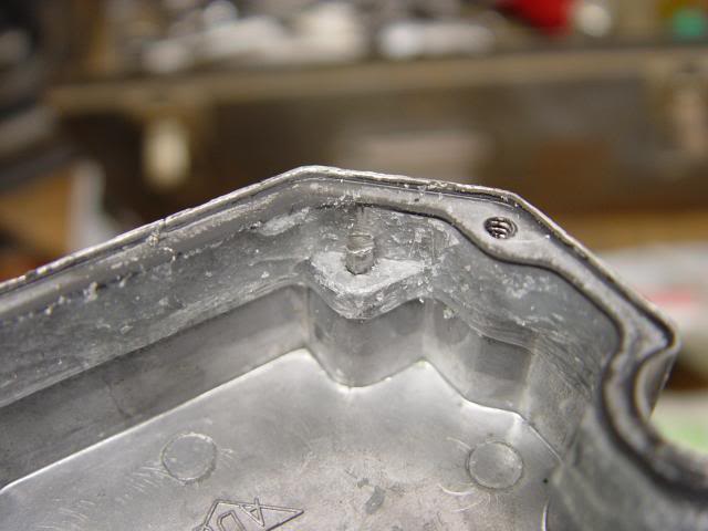
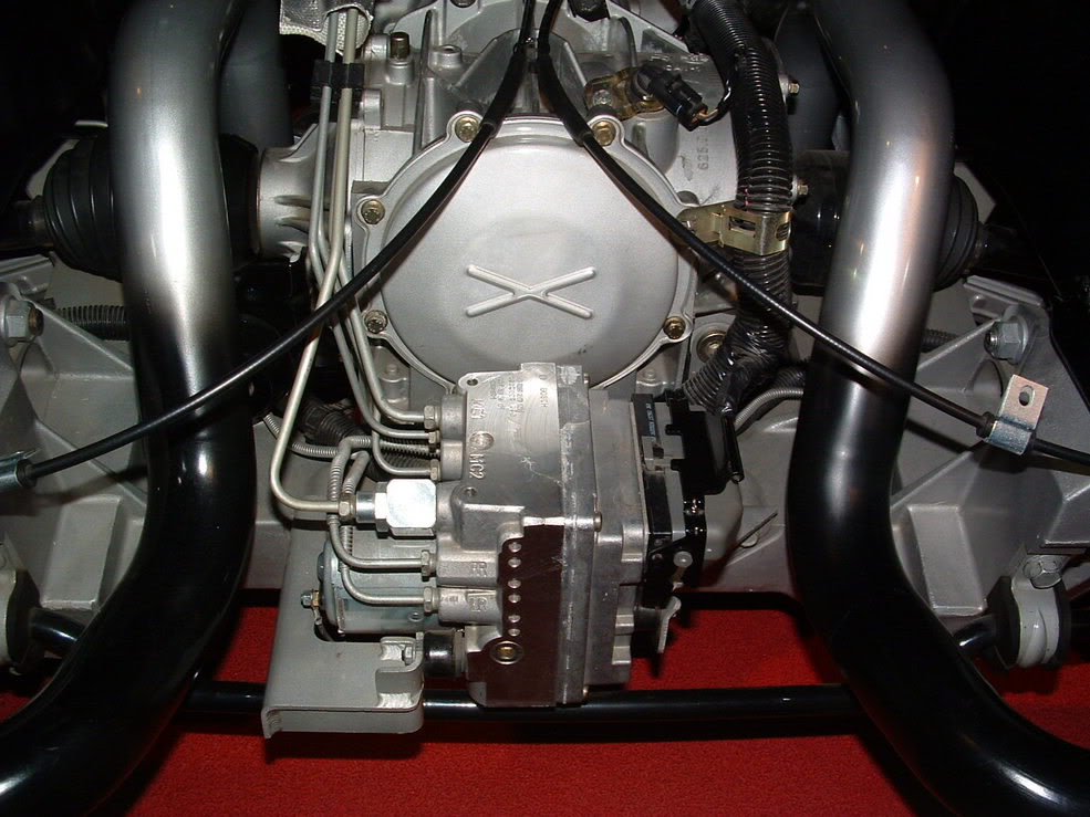
I didn't have a clear understanding of that hole in the cover until I got mine apart. It is a 1/8" passage through the shell to the front plate - you cannot hit a circuit board even if you wanted to. I used a Craftsman 1/8" punch, set the closest beveled mounting ear on a bench vise, and kept hammering until the sound changed indicating that the bead had broken. Then screwdrivers all around to finish separating the silicone.
An alternative to the punch would be a self-tapping screw that has a minor diameter of around 1/8" to get a good bite. Sorry I don't have an exact dimension, but hopefully this helps.
I second the comments by blackdak318 to get a hot iron. I had a little pointy 15W that worked on the smaller terminals, but didn't have enough oomph to melt the large center lug. The old 120W gun made short work of it.
I also pass my thanks on to all the contributors here. This forum is invaluable.
Todd
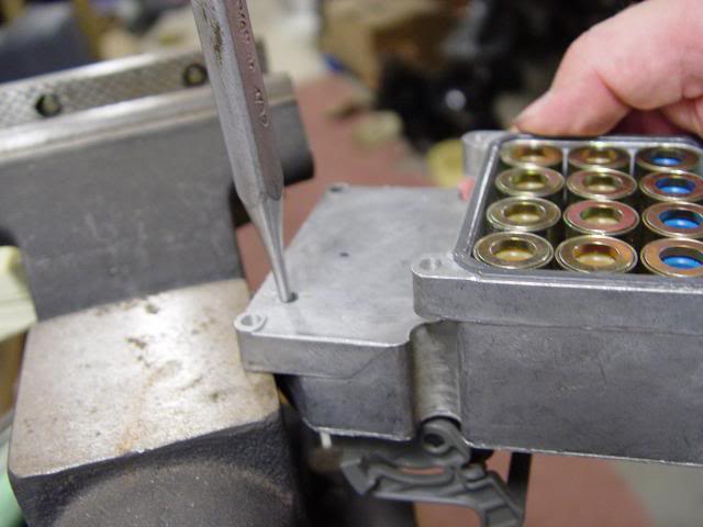
Picture of my 1/8 punch in the hole.
I didn't have a clear understanding of that hole in the cover until I got mine apart. It is a 1/8" passage through the shell to the front plate - you cannot hit a circuit board even if you wanted to. I used a Craftsman 1/8" punch, set the closest beveled mounting ear on a bench vise, and kept hammering until the sound changed indicating that the bead had broken. Then screwdrivers all around to finish separating the silicone.
An alternative to the punch would be a self-tapping screw that has a minor diameter of around 1/8" to get a good bite. Sorry I don't have an exact dimension, but hopefully this helps.
I second the comments by blackdak318 to get a hot iron. I had a little pointy 15W that worked on the smaller terminals, but didn't have enough oomph to melt the large center lug. The old 120W gun made short work of it.
I also pass my thanks on to all the contributors here. This forum is invaluable.
Todd
Picture of my 1/8 punch in the hole.
08-27-2011, 05:18 PM
#66
I pulled mine out of my 03 ZO6 and sent it to someone I found on Ebay. They fixed it for $50 and I didn't have to pull it apart. It's been working perfectly for the last two years.
08-30-2011, 01:34 AM
#68
Instructor

Member Since: Mar 2010
Location: Sacramento CA
Posts: 129
Likes: 0
Received 0 Likes
on
0 Posts
Just completed this a few minutes ago on my '02. I just re-flowed the solder (with some new) on the existing relay. After clearing all the historical codes, no new ones are returning.
I didn't have a clear understanding of that hole in the cover until I got mine apart. It is a 1/8" passage through the shell to the front plate - you cannot hit a circuit board even if you wanted to. I used a Craftsman 1/8" punch, set the closest beveled mounting ear on a bench vise, and kept hammering until the sound changed indicating that the bead had broken. Then screwdrivers all around to finish separating the silicone.
An alternative to the punch would be a self-tapping screw that has a minor diameter of around 1/8" to get a good bite. Sorry I don't have an exact dimension, but hopefully this helps.
I second the comments by blackdak318 to get a hot iron. I had a little pointy 15W that worked on the smaller terminals, but didn't have enough oomph to melt the large center lug. The old 120W gun made short work of it.
I also pass my thanks on to all the contributors here. This forum is invaluable.
Todd
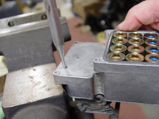
Picture of my 1/8 punch in the hole.

I didn't have a clear understanding of that hole in the cover until I got mine apart. It is a 1/8" passage through the shell to the front plate - you cannot hit a circuit board even if you wanted to. I used a Craftsman 1/8" punch, set the closest beveled mounting ear on a bench vise, and kept hammering until the sound changed indicating that the bead had broken. Then screwdrivers all around to finish separating the silicone.
An alternative to the punch would be a self-tapping screw that has a minor diameter of around 1/8" to get a good bite. Sorry I don't have an exact dimension, but hopefully this helps.
I second the comments by blackdak318 to get a hot iron. I had a little pointy 15W that worked on the smaller terminals, but didn't have enough oomph to melt the large center lug. The old 120W gun made short work of it.
I also pass my thanks on to all the contributors here. This forum is invaluable.
Todd
Picture of my 1/8 punch in the hole.
08-30-2011, 08:44 AM
#69
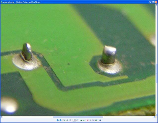
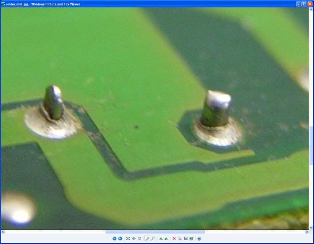
Here's a pic I took before my repair, and have zoomed in on two of the terminals in question. You can see it in the OP's 3rd pic too, on the relay center terminal. It appears as if a rift/ridge barrier has formed between the post & the circuit board it should be connected to. Re-melting the solder and adding some new took care of my C1242. As Lucky said above, "a classic case of insufficient solder/cold solder joints". Not sure exactly which it is (because all of my solder joints have never looked like this
 ), but clearly the solder is not doing it's job of connecting part A to part B. My worst looking terminals were on the load-side of the relay. Perhaps high current, vibration, and repetition along with lack of solder are a formula for this type of failure. Clearly the joints did work for 7+ years before failing, and mine was intermittent for several months before going consistent.
Todd
Last edited by toddk; 08-30-2011 at 08:47 AM.
08-30-2011, 08:49 AM
#70
Tech Contributor
Here's a pic I took before my repair, and have zoomed in on two of the terminals in question. You can see it in the OP's 3rd pic too, on the relay center terminal. It appears as if a rift/ridge barrier has formed between the post & the circuit board it should be connected to. Re-melting the solder and adding some new took care of my C1242. As Lucky said above, "a classic case of insufficient solder/cold solder joints". Not sure exactly which it is (because all of my solder joints have never looked like this
), but clearly the solder is not doing it's job of connecting part A to part B. My worst looking terminals were on the load-side of the relay. Perhaps high current, vibration, and repetition along with lack of solder are a formula for this type of failure. Todd
 09-14-2011, 02:18 AM
#73
Instructor
Member Since: Mar 2010
Location: Sacramento CA
Posts: 129
Likes: 0
Received 0 Likes
on
0 Posts
09-20-2011, 03:45 PM
#74
Tech Contributor

Member Since: Dec 1999
Location: Anthony TX
Posts: 32,736
Received 2,180 Likes
on
1,583 Posts
CI 6,7,8,9,11 Vet
St. Jude Donor '08

TTT
09-20-2011, 08:43 PM
#75
Drifting
Thread Starter
Thanks to all who've attempted this, if it weren't for you guys I wouldn't be as sure of this fix as I am now. Of course there isn't any issue with mine, but it certainly helps to see so many follow this write and clear codes permanently.


 10-16-2011, 05:22 PM
#78
Tech Contributor
Member Since: Dec 1999
Location: Anthony TX
Posts: 32,736
Received 2,180 Likes
on
1,583 Posts
CI 6,7,8,9,11 Vet
St. Jude Donor '08
Short answer,,,, no
10-16-2011, 05:25 PM
#79
Tech Contributor
Member Since: Dec 1999
Location: Anthony TX
Posts: 32,736
Received 2,180 Likes
on
1,583 Posts
CI 6,7,8,9,11 Vet
St. Jude Donor '08
Long answer,, Its a completely different EBTCM. Do you have a front or rear mounted EBTCM??
Rear Mount =
BC
Rear Mount =
BC