When you click on links to various merchants on this site and make a purchase, this can result in this site earning a commission. Affiliate programs and affiliations include, but are not limited to, the eBay Partner Network.
I wanted to share my experience of installing the Diode Dynamics Led Tail Light Halos in my '05 C6 with you. Hopefully it can help someone with installing these great looking lights. I have to give credits to BAAD LS2 for writing his awesome how-to on installing Halos. You can find it here: https://www.corvetteforum.com/forums...ght-halos.html. Read it first. I followed his how-to but noticed a few details I would like to add.
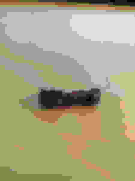
This is how the lights arrive:
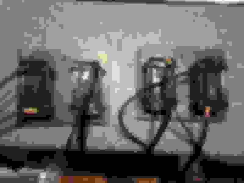
Contents of the box:
2 led rings, 2 inverters, 2 wire harnesses and some T-taps to tap into the car harness.
These are the T-taps. The wire of the car's harness is placed between the small knives which cut through the insulation. Personally I do not like these connectors. I have experienced that the vibrations of the car make it that, over time, the knives cut through the wire completely in combination with metal fatigue and fails. I therefore didn't use them and soldered everything.
I first removed the light assemblies from the car and taped up the holes to prevent rain from entering. They are easily removed by removing the T15 torx screw near the top of the assembly.
The next part is to bake the assemblies in the oven to be able to remove the red lenses. BAAD LS2's guide covers this well so I do not repeat it. I do want to add:
- The plastic trim removal tools didn't work for me. The tools bent instead of applying force on the assemblies. I ended up using a wide flat head screwdriver.
- For me it worked best to bake the lights for 5 minutes in a pre-heated oven at 140 �C (284 �F).
The adhesive partially stook to the lenses and reflectors in my case. After cooling-down it becomes hard. With a flat head screw driver you can peel it out.
Note that the left and right assemblies are different. You can see it here: There is an angle in the reflector, diffuser and lenses which follow the curve of the back of the car. The diffuser and lenses of the left assembly will not fit the right reflectors properly. Also note the indentation near the top of the reflector: The diffuser lenses only fit in one manner on the reflectors. There is a single tab on the diffuser which sticks out to locate the diffuser on the reflector.
Next is installing the led rings on the diffusers. The wires on the back of the led ring make it impossible to mount it flush without some modifications.
I made a small indent on the diffuser lens with a Dremel for the wire to fit in. These led rings fit between the tabs of the diffuser lens so you do not have to cut them off (contrary to the Oracle's in BAAD LS2's guide).
The led rings are connected to the inverters via a JST plug. The plug/wire needs to exit the light assembly. I didn't want to cut a large hole in the assembly so I cut off the connector.
Next I drilled a 5 mm hole in the reflector's housing and fed the wires through. Then I soldered the connector back on. As stated in BAAD LS2's guide you also need to make a slot in the red lens for the wire to fit through.
Next step is optional. I painted the middle of the diffuser lenses black as explained in BAAD LS2's guide. Here are some comparison pictures.
Stock light:
Stock light with black diffuser:
You can see some oils on the parts. Before final mounting I used alcohol to clean everything. Be warned about the reflective material: This can be removed by the alcohol as well!
Next I mounted the led rings on the diffuser lenses and placed them on the reflector housings (remember they will only fit in one manner). I used a small amount of plastic glue on 3 points to hold the rings in place (preventing them from moving out of center while handling the assemblies). I assume these led rings are higher than the Oracle's since it they stick out above the taps of the diffuser lens (contrary to BAAD LS2's experience). As a result the red lens sits slightly higher and wedges the led ring between the diffuser and the red lens. You therefore do not need to use a lot of glue to hold the led rings down.
I used transparant silicon sealant to replace the original adhesive. During hardening I taped the red lenses to the reflector housing. This way the led rings are wedged in.
The next step is to mount the assemblies in the car. I went looking for a place to mount the inverters and noticed a possibility:
This is some kind of an earth rail. The nut can easily be removed and there is one on either side of the car.
I made a bracket from some left-over sheet aluminium for mounting the inverters. These are 12x10 cm so they fit through the hole of the lights (they are 18 cm wide).
Then I painted them black for extra horsepower and mounted the inverters. They are glued and strapped down by tie-wraps.
Here you can see the inverters mounted in the car. The casing of the inverters is non-conductive so there is no issue with grounding.
The final step is to tap / solder into the existing wiring harness on the car. On the inverter's harness there are 4 wires:
White: Low Power, 50% brightness
Red: High Power, 100% brightness
Amber: Signal
Black: Ground
On the car harness there are 3 wires:
Black: Ground
Tan: Running lights
Yellow (left) or Green (right): Brake and turning signals.
The led rings of Diode Dynamics have a dual intensity mode. On their site the following is stated:
"The white and red wires both activate 6000K white color, at different brightness levels. Your order will ship by default with "low priority" drivers, meaning that if both wires are powered, low power will take priority. This is convenient for connecting the red wire to a parking light or DRL signal, for use during the day as a high-power DRL. Then, if the white wire is connected to the headlamp power, they will dim down at night. Of course, this is completely optional, and you can just use one of the input wires if you'd like.
I tried both options and I noticed the 50% brightness option to be brighter than every other DRL on the other cars around the house. In the dark the effect is even more pronounced. To avoid blinding and irritation of other road users (especially during night) I opted to use the 50% option. During daytime the 50% option is still more than bright enough to stand out. I let the red wire disconnected. The white wire is connected to the tan wire on the car's harness. Black to black.
Diode Dynamics state on their site:
The signal wire will output even higher power to the ring, so it cannot be run constantly, or the driver will overheat. It should only be connected to a turn signal. If you'd like amber for a running light, please select the single color amber rings instead."
This worried me since the brake light is the same wire as the turning light on the C6 and could be applied for longer periods of time. I therefore contacted Diode Dynamics and asked which wire to use (Red or Amber). Their response:
Hello,
Thanks for reaching out to us. You really could do either. With it being high power on the brake light, even if you are on the break for an extended period of time it would be okay. Basically, you just don't want it on constant high power all of the time. Let us know if you have any other questions or concerns.
Best Regards,
Josh S.
So I just the used the amber wire. Connect it to the yellow or green wire of the car's harness.
Here is the diagram of the car's harness (tail lights near the bottom of the diagram):
Second part (not needed):
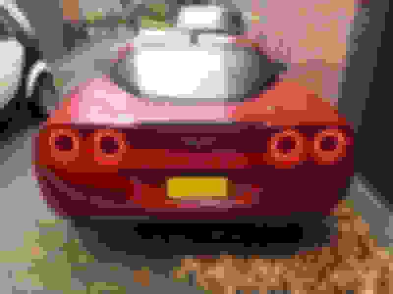
Here is the end result. Lights off:
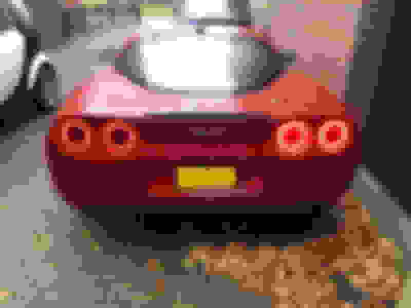
DRL:
Right turn signal (same as brake):
Turn / brake signal is extremely bright!
Thanks for reading and wish you the best with the installation!
Thank you for this post! I paid Mike from Vettesthetics to do the led ring install & have the lights sitting in a box waiting for the install....your wiring explanation is very helpful as I also had a question with the 50% /100% option, I guess that I have no excuse now to get out there & install them...Nice idea with the inverter mounts also!
I also did not like the T taps that were supplied with the kit, so I went with these, these connectors can be dis assembled if needed and hold the wires securely & are vibration proof
I was able to get the left side done yesterday. I wired just the rings and left the bulbs disconnected. I didn't paint the defusser center black either. Wanted to keep the light as stock looking as possible. I wired Black to Black, Yellow to Yellow/Green, and Red to Brown. Going to look for some two sided tape today. Not mentioned in the article was how to reattach the rubber seal that you need to remove before baking. Another thing I thought of was that since I have a 6 speed, I don't think I have to worry about overheating since I don't normally keep my foot on the brake at stop lights or heavy traffic like you would an automatic. Other than that I love them and was a great compliment to the Orical LED side markers I have installed. One other thing I'd like to mention. Keep an eye on the lens as your baking. I baked at 280 deg's for 5 minutes, but all ovens might not be exactly that temp? my first lens puckered a little bit, but was able to use a heat gun and push back out. emerging the lens in cold water will cure it quickly as well.
I was able to get the left side done yesterday. I wired just the rings and left the bulbs disconnected. I didn't paint the defusser center black either. Wanted to keep the light as stock looking as possible. I wired Black to Black, Yellow to Yellow/Green, and Red to Brown. Going to look for some two sided tape today. Not mentioned in the article was how to reattach the rubber seal that you need to remove before baking. Another thing I thought of was that since I have a 6 speed, I don't think I have to worry about overheating since I don't normally keep my foot on the brake at stop lights or heavy traffic like you would an automatic. Other than that I love them and was a great compliment to the Orical LED side markers I have installed. One other thing I'd like to mention. Keep an eye on the lens as your baking. I baked at 280 deg's for 5 minutes, but all ovens might not be exactly that temp? my first lens puckered a little bit, but was able to use a heat gun and push back out. emerging the lens in cold water will cure it quickly as well.
I'm getting ready to do this install as well and have been debating on 1. painting defuser and 2. leaving stock bulbs wired.
I'm getting ready to do this install as well and have been debating on 1. painting defuser and 2. leaving stock bulbs wired.
do you have pics of yours ?
This one is with the running lights on (no bulbs) will take another pic with lights off to get a comparison from left to right. I can tell you though, unless your up close, you won't notice the difference
I'm in the process of doing mine. I bought a set of tail lights for the .I'd so.i could do it while still driving with my stock taillights.... just in case I screwed something up.
I got all 4 lights apart and over heated one light so it has a very small indentation. However, once I saw that, I went back and checked the other ones and two others have a slight deformed dome. One is near perfect. I find it hard to believe this mod can be done without ANY deformity.
My question is, will the slightly warped taillight be obvious? Or will it really not be noticable? Maybe I'm just being too ****? Lol
I was going to be anul about it too and order another taillight, but decided to go ahead and install it. Unless your up close looking from the side you can't tell. When I do the other side, I think I'm going to do about 200 deg, not 250 or 280
I was going to be anul about it too and order another taillight, but decided to go ahead and install it. Unless your up close looking from the side you can't tell. When I do the other side, I think I'm going to do about 200 deg, not 250 or 280
Thanks for the input. I figured it wouldn't be TOO noticable, so I'll continue. I went 240 at first, but wasn't quite enough. 270 for 7-8 minutes seems pretty good. Any longer or hotter causes issues.
Wanted to mention this in case anyone else has this problem after installing the halo's. I'm getting all kinds of static thru the radio now when applying the brakes, turn signals, running lights, etc.... I wrote diode dynamics and got this reply. I'm going to order these and give them a try. Let ya know how it works out.
Thanks for reaching out to us! What you are seeing unfortunately is some RF interference caused by the LEDs, one of those things that is inherent with that type of lighting in some cases. Your best bet is to install some ferite beads. This will suppress that RF interference. You can find these on Amazon all day. These simply clamp on to the wires. You will want a couple pairs on the wires coming from the drivers. Maybe a pair on the harness it's tapped into as well. Let me know if you have anymore questions!
I wonder if instead of painting the entire center of the diffuser black, if you were to mask off a small Corvette flag emblem, and leave it clear, if that would appear to where you could just see it faintly.
I wonder if instead of painting the entire center of the diffuser black, if you were to mask off a small Corvette flag emblem, and leave it clear, if that would appear to where you could just see it faintly.

 12-08-2018, 11:37 AM