
Ttix no boost control
 12-31-2020, 06:30 AM
#41
Instructor

Thank you Stevie for help!
1. I presume/hope you mean the bottom chamber that blows the gate open ?
Yes Sir.
2. I would almost never use an intake vacuum source for control.
Any suggestion for a good source?
And I don't have pressure source on Turbo units
Also...your numbers seem contradictory to Turbosmarts instructions, as well as the use of intake instead of near compressor control source. All these things will make a big difference. Although 38mm may be a little small. But fix the plumbing first.
I didn't use this because I saw this setup for straight engines.
Don't you think my current plumping is fine?
This is the most basic setup you can use, if you cannot achieve your low boost target with this arrangement, then you need more gate flow.
 12-31-2020, 07:07 AM
#42
Melting Slicks


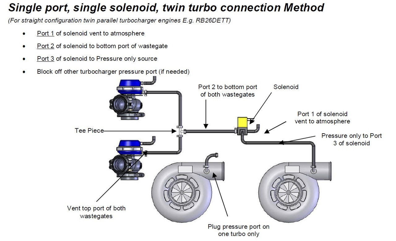
The hoses must be connected to the correct ports. The above configuration is for any twin setup using 2 gates and a single solenoid which I presume is what you are doing.
If you cannot get a boost source at the compressors themselves, you could maybe drill/tap a boost pipe or the turbo side of the intercooler header tank or something. Given you are having issues with too much boost, I absolutely would not be using intake manifold for a source, or even the plumbing between IC and throttle.
Although a first easy step would be to configure the hoses and solenoid correctly as per their diagram..( retaining your intake reference for ease of the test, although not ideal ) It may be enough to lower your boost to a level you are happy with, even though I would almost always say trying to use intake manifold as the control source is wrong, and Turbosmart clearly tell you to use a pressure only source.
Last edited by stevieturbo; 12-31-2020 at 07:09 AM.
12-31-2020, 07:31 AM
#45
Instructor
The hoses must be connected to the correct ports. The above configuration is for any twin setup using 2 gates and a single solenoid which I presume is what you are doing.
If you cannot get a boost source at the compressors themselves, you could maybe drill/tap a boost pipe or the turbo side of the intercooler header tank or something. Given you are having issues with too much boost, I absolutely would not be using intake manifold for a source, or even the plumbing between IC and throttle.
Although a first easy step would be to configure the hoses and solenoid correctly as per their diagram..( retaining your intake reference for ease of the test, although not ideal ) It may be enough to lower your boost to a level you are happy with, even though I would almost always say trying to use intake manifold as the control source is wrong, and Turbosmart clearly tell you to use a pressure only source.
If you cannot get a boost source at the compressors themselves, you could maybe drill/tap a boost pipe or the turbo side of the intercooler header tank or something. Given you are having issues with too much boost, I absolutely would not be using intake manifold for a source, or even the plumbing between IC and throttle.
Although a first easy step would be to configure the hoses and solenoid correctly as per their diagram..( retaining your intake reference for ease of the test, although not ideal ) It may be enough to lower your boost to a level you are happy with, even though I would almost always say trying to use intake manifold as the control source is wrong, and Turbosmart clearly tell you to use a pressure only source.
What about the BOV where should be the line connected to?
01-07-2021, 03:34 AM
#47
Instructor
After many emails with TurboSmart Tech Team, They said that my current 38mm wastegates should be replaced with bigger size and at least it should be 50mm!
I guess I will stick with what I have since it is to tight to put a dual 50mm wastegates.
I attached the BOV line to intake port.
01-07-2021, 04:11 AM
#48
Melting Slicks
Update:
After many emails with TurboSmart Tech Team, They said that my current 38mm wastegates should be replaced with bigger size and at least it should be 50mm!
I guess I will stick with what I have since it is to tight to put a dual 50mm wastegates.
I attached the BOV line to intake port.
After many emails with TurboSmart Tech Team, They said that my current 38mm wastegates should be replaced with bigger size and at least it should be 50mm!
I guess I will stick with what I have since it is to tight to put a dual 50mm wastegates.
I attached the BOV line to intake port.
It may be ok, or at least much better than it is now without the need for larger gates.
01-07-2021, 04:24 AM
#49
Instructor
What I want is to check if any of these lines leaking, and replace it with braided stainless steel lines to avoid any leaks issue and more heat resistance.
 01-07-2021, 12:47 PM
#50
Melting Slicks
There will always be a little leakage from the bottom chambers on the gate, down the valve stem, so don't expect it to seal perfectly. But the better they do seal, the more potential for the valve to be open further for any level of pressure, in the hope the gate may flow more.
And as always, keep lines as short as possible, especially the lines from the solenoid to the gate itself.
I run one solenoid per gate in order to keep the hoses short, which is also made even easier if you take the line off the compressor housing ( which is easy to drill/tap if it doesn't have a hole already )
Exactly what 38mm gate are you using ? Is it bolted ? v-band ? other ?