When you click on links to various merchants on this site and make a purchase, this can result in this site earning a commission. Affiliate programs and affiliations include, but are not limited to, the eBay Partner Network.
If the top of the F55 rear shocks need to be removed for any reason, be careful when unbolting the flange. The electrical connector is prone to damage when the tension is released. Place a support or jack under the lower control arm before removing the flange bolts. Make sure the connector and wiring harness have clearance around the mounting bracket hole as you lower the assembly.
If you're not reading this until after you broke the connector, here's the replacement PN. 19180262
Don't let the dealership tell you the connector only comes as part of the PN 19177205 shock assembly (about $700), because that's all that shows up on their main computer parts access.
Many thanks to Adrian and Jesse at Sands Chevy in AZ for spending the time to find it among the hundreds of items of individual parts in other portions of the system.
The replacement connector I received was not 100% identical to the original from my 10-30-07 build date '08. Apparently there was a slight change, but the newer one can be made to work.
NOTE: If your original is beige, disregard the following mod.
The original on the right is black and is partially broken where the retainer spring fits.
Notice that the beige replacement part is longer where the wiring harness connects.
To get the harness connector inserted you must sand/grind approximately 1/8" off that end. Test fit to the harness or compare measurements to the original to avoid removing too much material. Do not attempt to saw, slice, snip, or use any other methods to reduce the size, as this type of plastic is prone to cracking. I had excellent results with a belt sander. Put tape over the part that fits on the shock to keep out any crap. You'll need to scrape the burr off, that the sanding created and blow out any dust.
When installing, put the harness connector on first and then depress the spring and install on the shock. When the connector is seated, release the spring. Don't forget to replace the bungee.
Be careful when remounting the shock, as it's easy to crack the connector as it goes through the shock mount hole.
If the top of the F55 rear shocks need to be removed for any reason, be careful when unbolting the flange. The electrical connector is prone to damage when the tension is released. Place a support or jack under the lower control arm before removing the flange bolts. Make sure the connector and wiring harness have clearance around the mounting bracket hole as you lower the assembly.
If you're not reading this until after you broke the connector, here's the replacement PN. 19180262
Don't let the dealership tell you the connector only comes as part of the PN 19177205 shock assembly (about $700), because that's all that shows up on their main computer parts access.
Many thanks to Adrian and Jesse at Sands Chevy in AZ for spending the time to find it among the hundreds of items of individual parts in other portions of the system.
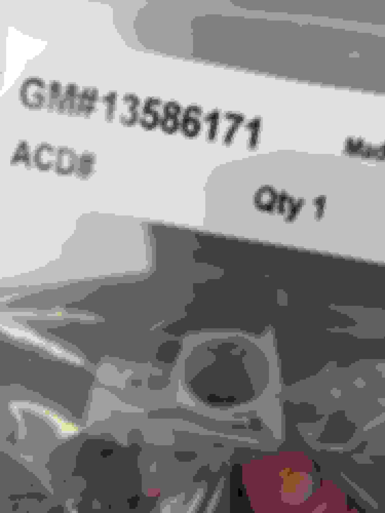
As info the part number has been superceded with p/n 13586171. About $16 from any of the gm part wholesalers.
I know this is an old thread but does anyone know the correct part number for the REAR shock connectors as well? The front connector part number #13586171 is correct.
I believe it is the same. I replaced my rear connector with that part number.
They are physically different connectors, the fronts are gray and the rears are black and have a short harness attached as well. I believe I have found the correct part number (#88956499). I am going to order one its $40 from gm parts now and it lists it for the ZR1 and several models of Cadillacs.
They are physically different connectors, the fronts are gray and the rears are black and have a short harness attached as well. I believe I have found the correct part number (#88956499). I am going to order one its $40 from gm parts now and it lists it for the ZR1 and several models of Cadillacs.
I also need the rears the part number you listed is discontinued. Any ideas???
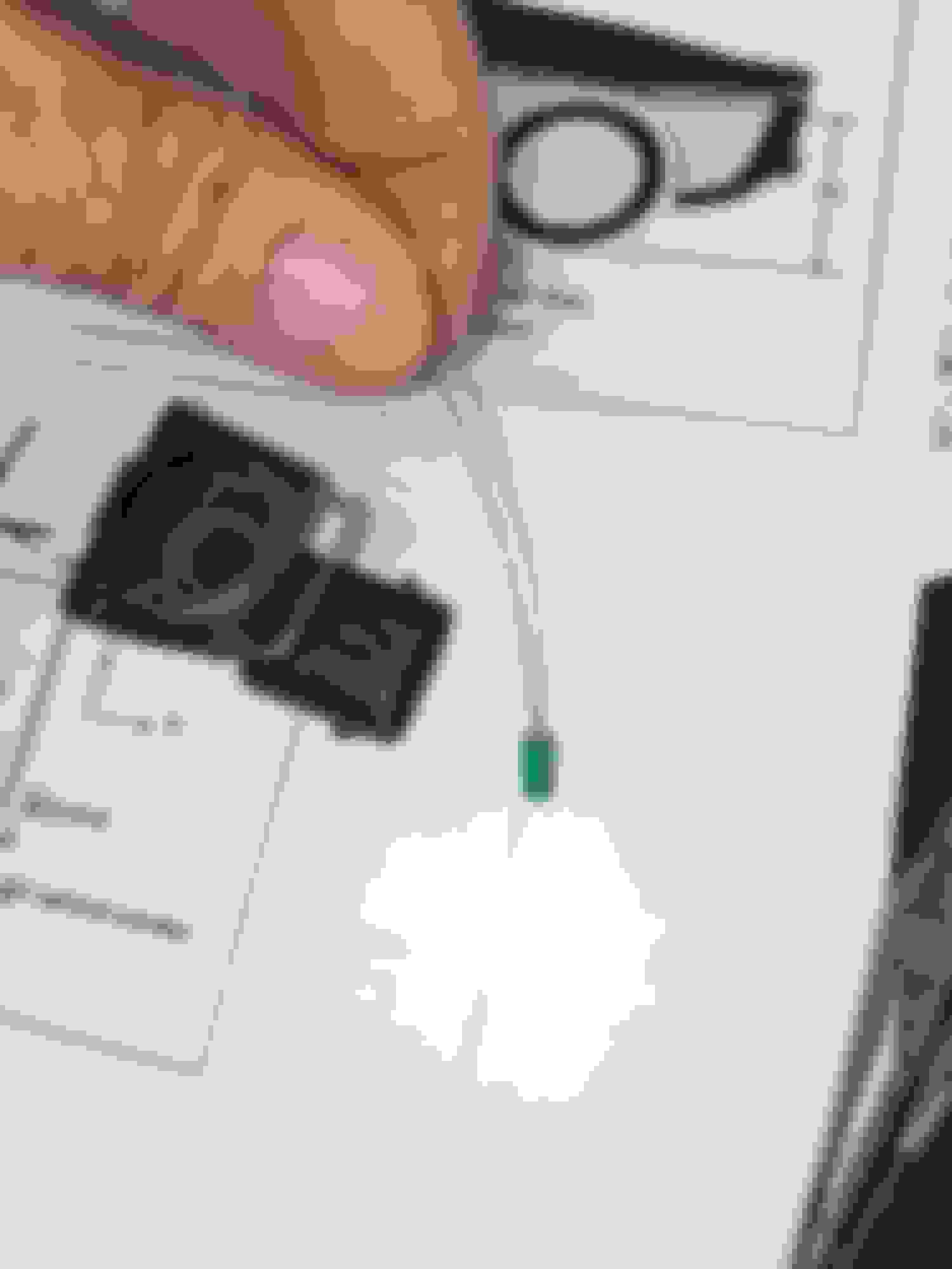
Sam, I'm in the same boat... purchased the GM Multi-purpose connector 13586171 - easy to mod the harness side with sand paper BUT the center post on the shock end it longer than the original connector so it won't go down far enough for the wire clip to snap over the shock landing. Arrow points to the center post that is too long. I would have thought either the connector post or the shock post would be spring loaded but doesn't appear to be.
Sam, I'm in the same boat... purchased the GM Multi-purpose connector 13586171 - easy to mod the harness side with sand paper BUT the center post on the shock end it longer than the original connector so it won't go down far enough for the wire clip to snap over the shock landing. Arrow points to the center post that is too long. I would have thought either the connector post or the shock post would be spring loaded but doesn't appear to be.
Same. I bought those clips in your picture and also shaved them down. Indeed they would not seat. I kinda forced them down. One of them I had to lightly tap with a rubber mallet.
For all I know I ruined it... I still get the "shocks inoperative, service ride control, max speed 80mph" message
I scanned it with BlueDriver (Jim Mero mentioned that he's also used BlueDriver code reader and it's told him specifically which mag ride sensor failed)
The fact that mine isn't telling me which sensor failed but rather that it's "lost communication with the vehicle dynamics control module" (the code I get is U0122)...does that mean I must have accidentally cut the harness somewhere when doing my clutch job?
Last night it occurred to me that one way to find out without having to drop the rear cradle and torque tube to inspect the harness is to purchase a set of those mag ride simulators...(around $200 ish) and install them...
I'm assuming that if I don't get the messages about max speed being 80 etc then that means my issue is just at the connection at the shocks...
versus if I still get the messages then indeed I did manage to cut a cable somewhere and ruin the connection...
(My first guess would be somewhere above the bell housing as I had to use a prybar to get to the top bolt... And as I type this I realized maybe the actual short harnesses that clip from the main harness to each rear shock might've got stretched out as I dropped the rear cradle and snapped the clips in the first place....)
I resolved my problem - error C0590 RR Actuator Circuit Open Symptom 04 When I broke the connector removing the rear cradle. When the connector broke it left half of the connector post (the arrow points to it) on the shock pin so the replacement connector would not go down all the way. Once I removed the broken piece from the shock pin the new connector snapped right into place. The only mod is removing material from the harness side of the connector (black line on pic) so the harness clips fasten. To confirm I set my meter to autorange Ohm's and checked the shock first one lead to the center pin of the shock, other lead to the nut. I got a steady 1.5 ohms but believe the range is .5 to 3.5 then I put the connector on the shock and touched each lead to the pins on the harness side of the connector- got same reading then did the same for the harness where it connects by the cradle. All back together and no errors after a few power cycles. with the connector clipped onto the shock you should have steady .5 to 3.5 Ohms Mine was 1.5 ohms set meter for Ohms this is the replacement connector with post intact used a piece of safety wire to get broken piece off the shock pin. broken post (green piece) that was stuck on shock pin

 12-23-2009, 09:40 PM