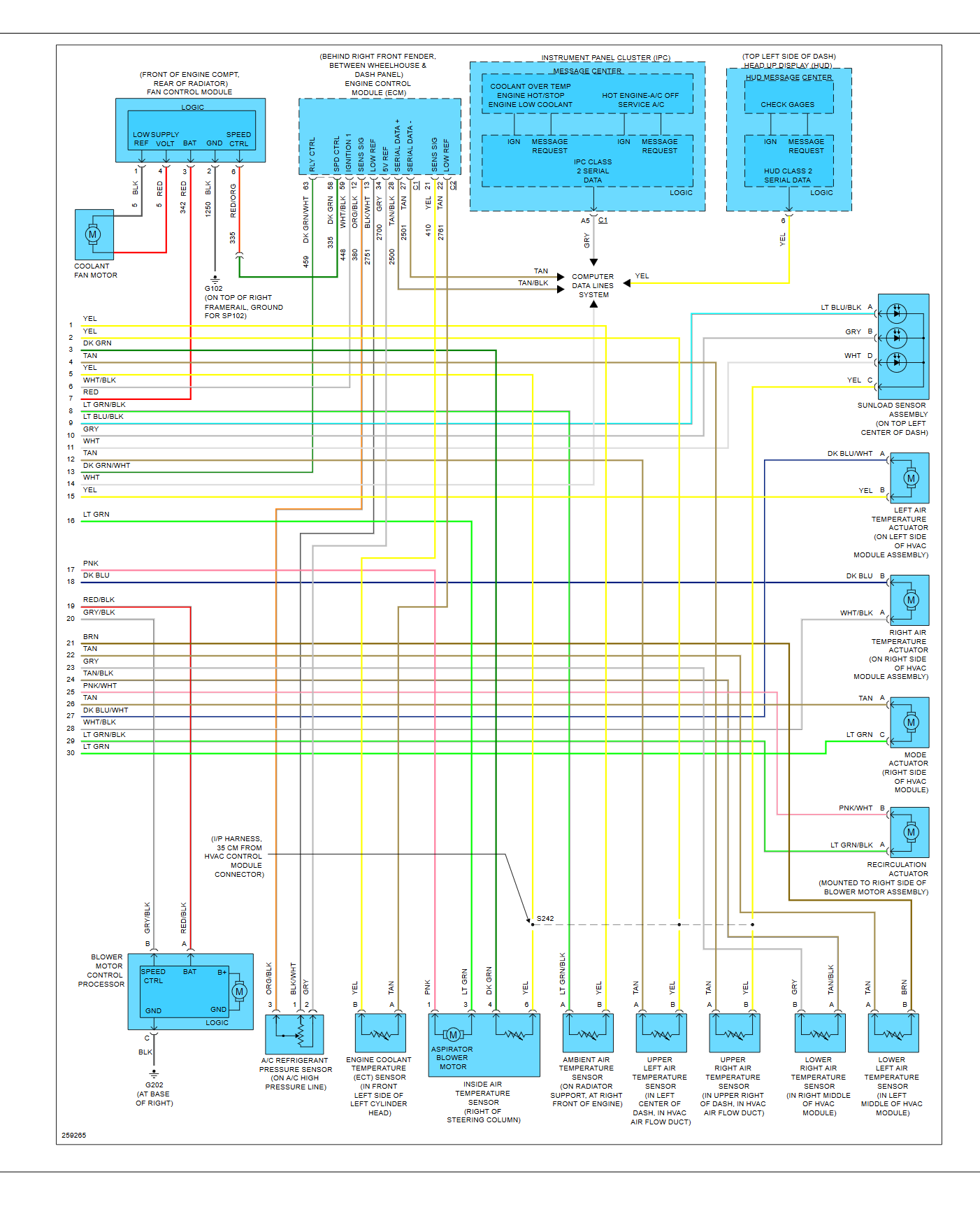
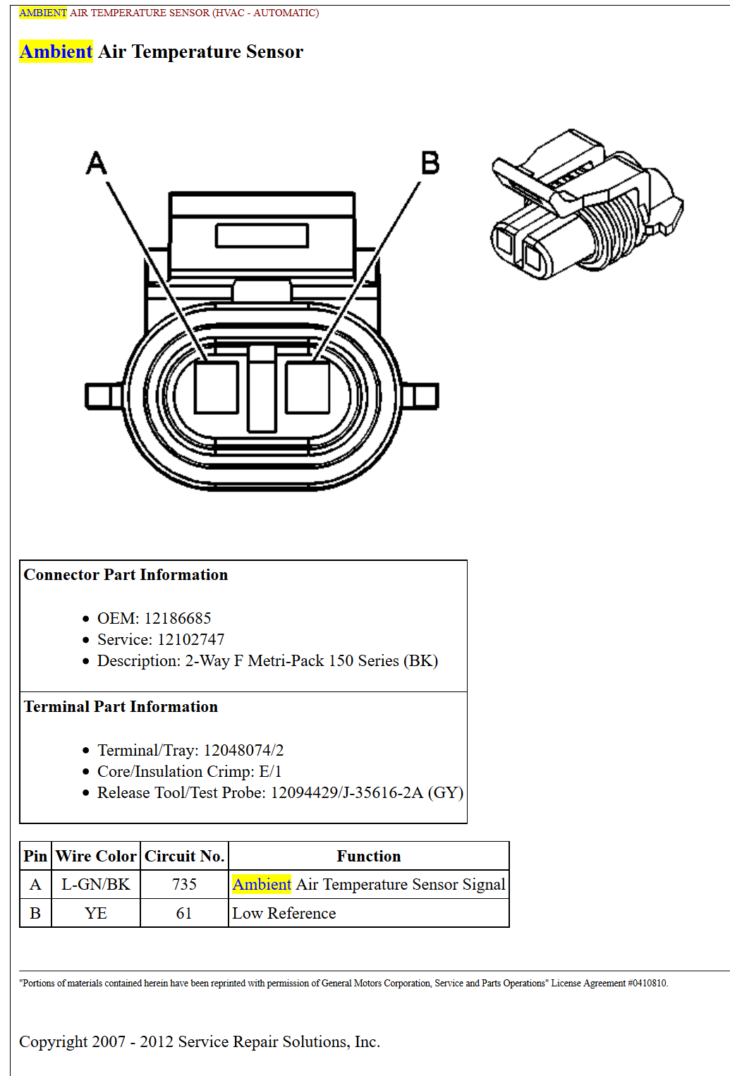
pin out or wiring diagram for C6 Ambient Air sensor
#1
Racer


Thread Starter
looking for a wiring diagram or troubleshooting flow chart for this. I swapped one from a know good car and still reads 75 whether its plugged in or not. I do have +5v on one side of connector so it has to be other side.
#2
Drifting


Member Since: Feb 2012
Location: skiatook oklahoma
Posts: 1,796
Likes: 0
Received 36 Likes
on
32 Posts

fyi... there is a reset, , to reset the outside air temp reading on HVAC.
press...............
Front Defrost, Rear Defog and fan up buttons simultaneously
sorry if i have misunderstood your problem
press...............
Front Defrost, Rear Defog and fan up buttons simultaneously
sorry if i have misunderstood your problem
#3
Racer


Thread Starter
yeah tried that. The issue is it reads 75 with or without the sensor plugged in so I have a open or something is wrong. I just bought car and PO supposedly had it fixed but now its not working. Sensor works fine in my 2002 that I am waiting on someone to pick up so sensor is ok. I have a slight overheating issue with AC on and it may or may not be part of it covering all bases. Its possible it uses the ambient temp to control cooling fan speed I hear it speed up and down all the time if its 95 out and thinks its 75 who knows???
#5
Racer


Thread Starter
how did you know it was controller? Did you take it out and trace ambient temp signal to it? Just trying to figure out the wiring diagram so I can do that. I suspect its wiring since the PO had it fixed before I bought it and it worked. Looking at where the sensor wires are its a little chewed up and pinched looking.
#6
Burning Brakes


Member Since: Mar 2008
Location: Williamsburg Virginia
Posts: 949
Received 0 Likes
on
0 Posts
I assumed it was the sensor at first, ordered a replacement and no change. I ohmed out both sensors (new and old) by placing them in the freezer and they both ohmed good, I do not remember the specs off hand but at certain temperature it should have certain amount of resistance.
I also checked the wires from the HVAC control to the sensor, they had proper voltage but the controller did not respond to placing the sensor in the freezer then connecting.
If memory serves me right, shorting out the senor wires back to the controller was another test, I do not recall what it did or didn't do off hand.
If your wires might be messed up, chop them then repair first then ohm the sensor and wires. If a few strands of wires are broken/pinced it could affect your sensor reading, if open and corroding that would also affect your resistance.
The HVAC controllers have been know to have bad solder connections, I didn't notice any obvious bad solder joints in mine.
When I tried the steps ChevyDave mentioned, it didn't make any difference for me.
Not really much to it, sensor, wires and controller.
#7
Race Car Tech
PM me your e-mail and I'll send you the full electrical diagrams. It may or may not have the info that your looking for however.
A.C diagrams (2) shows a pink wire (power supply) and yellow wire for the inside air temp sensor for the aspirator blower motor (all part of the sensor)
Controlling the air temperature inside the interior is the Left and Right temperature actuators, (the temperature switches controlled by the AC control module) and coming into play for that circuit, is the sunload sensor found on top of dash by the speaker grill.
Did you disconnect the battery? Sometimes that cures (resets) a lot of electrical gremlins.
Good luck, and do a follow up post if you find what the issue was when you find and fix it.
Thanks
#11
Racer


Thread Starter
I had ordered a new sensor before I started swaping ones, I just installed it and now its sitting at 89. I suspect it may be connector or pin related. It was just dangling around so I got a push pin on it to stabilize it to frame. Looks ok now.


