
[Z06] C6 Z06 Frequently Asked Questions(FAQ)
 02-06-2006, 09:53 AM
#41
Get Some!


Thread Starter

Read your owners manual, but these principals should equally apply to the C6 Z06.
Originally Posted by theadmiral94
In Other Words -- how to lift and support your C5 per the GM Manual
This article will translate and document the GM Manual�s procedures for lifting and supporting a C5 (based on a 2000) and clearly define the distinction between a �hydraulic jack� and where it can be placed -- versus -- �jack stands� and where they can be placed.
This is not to say other suggested procedures would not work without damage.
However, after struggling through so many different suggested procedures and the manual, I decided to put this together to help the next 'new to them' owner of a C5.
The goal of this write-up is to accurately convey the GM Manual�s information so anyone can determine if a suggested procedure deviates from GM recommendations.
This information is taken from GM�s 2000 Service Manual, Volume 1 of 3, General Information, pages 0-33.
I should also credit two other websites for their information, upon which some of this article is based :
:
The Idaho Corvette Page and Z06vette.com
First, to identify some large differences between many suggested procedures and what the GM�s manual recommends. The GM Manual states or implies:
1. �Jack Stands� should NOT be placed under the �frame rails� (regardless of whether �hockey pucks� are used or not).
2. A �hydraulic jack� should NOT be placed directly under the CENTER of the �OPTIONAL� front cross-member. The �Optional� Front cross-member is FORWARD of the front fiberglass transverse spring and is the �optional� front location for a �hydraulic jack�. By contrast, the �PREFERRED� front location is to the REAR of the fiberglass transverse spring, immediately forward of the oil pan. This 'PREFERRED' cross-member can have a 'hydraulic Jack' placed directly under the center, however, doing so will most likely contact and may damage the oil pan/oil drain plug, so it is NOT advisable either.
3. A �hydraulic jack� should NOT be placed directly under the CENTER of the rear cross-member to raise the rear of the car.
4. �Hockey Pucks� should NOT be used at the FRONT Frame Rail location when lifting the car with a �service lift�. The presumably larger flat rectangular �service lift� �pad� is to be placed with its long side parallel with and at or immediately forward of the front �hockey puck� AREA (note: this also assures a slightly higher rear end for proper oil draining from the oil pan).
Now on to what can be done.
First of all, here is the Service Manual�s vehicle diagram of the �Vehicle Lifting and Jacking Locations� (note: Jacking is NOT �Jack Stands�):
personal home page Lifting & Jacking Locations
The Service Manual has 3 sections within the �Lifting and Jacking the Vehicle section�. These sections can be easily switched and thereby confusing.
The FIRST SECTION is �Vehicle Lifting � Frame Contact Hoist� (i.e. a �service lift�). This section clarifies the use of the �hockey pucks� (special part # J43625) ONLY for the REAR, to be installed in the �rear frame rail shipping slots�. The presumably larger flat rectangular �service lift� �pad� is to be placed with its long side parallel with and at or immediately forward of the front �hockey puck� AREA (without a �hockey puck�) AND not touching the body panels.
The SECOND SECTION �Vehicle Jacking� (�Hydraulic Jack�, not to be confused with �Jack Stands� or a �service lift�) implies the use of �hockey pucks� front and rear by specifying the use of �2 � inch or smaller diameter lifting pads when �jacking� the car via the �frame rails�.
For the FRONT, this �Vehicle Jacking� section continues to specify the �Preferred� Front Suspension cross-member as the one behind the fiberglass transverse spring, immediately forward of the oil pan. This cross-member can be lifted anywhere along its width (center to 13� off-center), with the preferred location at the outer 7 � inches (and in the middle of that outer 7 � inches). Note, the usage of the �Preferred� cross-member may make oil changes difficult as the cross member is more narrow at the center where it comes very close to the oil drain plug.
Further specified in this �Vehicle Jacking� section is that the Front �Optional� front cross-member should only be lifted at the outer 5 � inches of the overall 26 inch cross-member�s length and NOT in the center (when you look at the cross-member, you will understand why).
For the REAR, Similarly specified is that a �hydraulic Jack� should NOT be placed in the center, it should only be placed at the outer and rearward sweeping 5 � inches (of the overall 26 inch length cross-member) (again, when you look at the cross-member and how it supports the body, you will understand why).
The THIRD SECTION �Supporting the Vehicle with Jack Stands� first notes �Important: Do not place jack stands under the frame rails�.
It further specifies that �Jack Stands� should only be placed under the outer areas of the three previously mentioned cross-members. Also, a �block or pad� should be placed between the jack stands and the vehicle. Lastly, make sure the �jack stands� �block or pad� span at least 2 cross-member ribs (i.e. side to side thin aluminum ridge).
Some Personal notes/thoughts:
The cast aluminum cross-members should only be lifted with specially constructed wood �pads� to prevent damage and possible cracking.
The car�s underbody is very low. There is only approximately 3� inches clearance below the front air dam, and only about 5 inches below most of the underbody, cross-members and side rails.
This low clearance creates a requirement for front and rear drive-on ramps with a minimum of 3� of lift to gain clearance to the cross-members for �jacking� with specially constructed wood �pads� and a low-profile hydraulic jack (e.g. #0950240 from Sears with 3�� to 18�� lifting range). Always first lift the front, otherwise there will not be enough clearance to do so after lifting the rear.

Now on to what you can make out of wood to comply with the GM Service Manual.
Here's a link to pictures of the home-made items:
Wood Ramps and Hydraulic Lifting Pads
Home Made Wood Ramps:
� Two 12 foot 2� x 12�
� One 8 foot 2� x 3�
� One box of #10 x 3� wood screws
Front: cut off 1� from the worse end of the first 2� x 12� and set aside. Then cut two 3 �� and two 2� sections.
Rear: cut off 1� from both ends of the other 2� x 12�, then cut two 3� and two 2� sections.
Both: cut eight 12� lengths for stop-blocks from the 2� x 3�. Four are for placing behind the tires after driving onto the ramps.
Cut a 30 degree angle on one end of each of the ten 2� x 12� sections. This can be done with a table-saw set at 30 degrees and each board held vertical (standing up) while passing between the guide and another guide/piece of wood (I used the first 1� section set aside, clamped to the table).
Otherwise, if you only have a hand-held electric circular saw (which cannot cut the proper 30 degree angle on a vertical end as when set flat on the board, its 30 degree setting will actually cut a 60 degree ramp instead), then instead just cut a 45 degree angle on one end of each of the ten 2� x 12� sections.
Assemble front ramps: 12� 2�x3� stop-block on square end of 2� 2�x12� on top of 3 �� 2� x 12�. Pre-drill and screw together (2 screws for stop-block, 4 screws for 2� to 3��).
Assemble rear ramps: 12� 2�x3� stop-block on square end of 2� 2�x12� on top of 3� 2� x 12�. Pre-drill and screw together. The two additional 1� 2� x 12� sections are for placing under the tires after jacking to elevate the rear for proper oil draining. However, there may not be sufficient clearance to driver all the way off of the 3 levels, so you could roll off the 3rd level, then remove the 3rd level board before continuing down off the rest of the rear ramps.
Usage: Place the FRONT ramps with the stop block where you want the front tires to end up. Pull car just up to the ramp incline. Push the ramps up against the front tires and align the front ramps. Place the REAR ramps 6� in front of the rear tires and align (I use a 6� piece of wood as a spacer against the tire). Back car up without hitting any front mud flaps on rear ramps and accelerate smoothly. The car should hit the front ramp�s 1st level, then the rear ramp�s 1st level, then front and rear ramp�s 2nd levels almost simultaneously. Be sure the car is against the stop-blocks and set parking brake. Then set the four additional stop blocks behind each tire.
NOTE: The front ramps are only 3 �� long to be clear of the �hockey puck� area, in case it is needed for �hydraulic Jacking�. The rear ramps are only 3� and set 6� forward of the rear tire to prevent hitting both ramps at the same time thereby reducing the chance of their movement and insufficient speed to achieve making the 2nd level of both ramps.
Home Made Wood Hydraulic Jack Lifting Pads
Here's a link to pictures of the home-made items:
Wood Ramps and Hydraulic Lifting Pads
� One 8 foot 2� x 6�
� One 8 foot 2� x 8�
� #10 3 inch wood screws
NOTE: The 'optional' Front wood lifting pad may be needed to be able to reach and use the Front 'recommended' cross-member and its wood lifting pad, especially when using the above mentioned 3 inch ramps and the above mentioned Sear's hydraulic jack. (i.e. lift/support at 'optional' cross-member, then lift/support at 'recommended' cross-member for long-term storage or extensive work).
For FRONT �Optional� cross-member: cut two 6� sections, and one 26� section from the 2� x 6�. Assemble each 6� section on top, flush with the ends and parallel with the 26� section. Pre-drill and screw together.
When used on the �Optional� front cross-member (area forward of the fiberglass transverse leaf spring), center the wood (side to side and front to back) with the 6� sections on top against the cross-member and contacting both front and rear �RIB� with the hydraulic jack centered underneath the 26� section. Pre-drill and screw together. This way lifting pressure will NOT be applied under the center of the cross-member, only the ends, as specified by the GM Manual.
For FRONT �Recommended� cross-member: cut two 8� sections and one 26� section from the 2� x 8�. Assemble each 8� section on top, flush with the ends and parallel with the 26� section. Pre-drill and screw together.
When used on the �Recommended� front cross-member (area behind the fiberglass transverse leaf spring and immediately forward of the oil pan), center the wood (side to side and front to back) with the 8� sections on top against the cross-member and contacting both front and rear �RIB�, with the hydraulic jack centered underneath the 26� section. This way lifting pressure will NOT be applied to the middle of the cross-member where the wood would overlap the oil pan and oil drain plug. This could also allow still doing the oil change while the wood is in place.
�Jack Stands� should only be used with these wood lifting pads, placed underneath the ends of the 26� section on either side of the hydraulic jack (�Jack Stands� should NOT be placed under the �hockey pucks� on the frame rails).
For REAR cross-member: Cut two 10� sections and one 26� section from the 2� x 6�. Assemble each 10� section on top, at each end, but perpendicular to the 26� section, somewhat centered, except that 3� should extending rearward of the 26� section, and 1�� should extending forward of the 26� section (looks like a �U� with downward legs when assembled).
When used on REAR cross-member, center (side to side and front to back) the 26� section on the center of the rear cross-member directly under both �ribs�, with the 10� sections upward and against the cross member and pointing rearward so as to ALSO be underneath the cross-member ends which are more rearward (tie-rod ends). Place the hydraulic jack centered underneath the middle of the 26� section. This way lifting pressure will NOT be applied under the center of the cross-member, only the ends, as specified by the GM Service Manual.
�Jack Stands� should only be used with this wood lifting pad, placed underneath the ends of the 26� section and centered below the 10� sections on both sides of the hydraulic jack (�Jack Stands� should NOT be placed under the �hockey pucks� on the frame rails).
Set the rear �jack stands� one (1) notch higher than the front �jack stands� for a level car.
Set the rear �jack stands� two (2) notches higher than the front �jack stands� when performing an oil change (will level/slightly tip the oil pan to fully drain the oil).
This article will translate and document the GM Manual�s procedures for lifting and supporting a C5 (based on a 2000) and clearly define the distinction between a �hydraulic jack� and where it can be placed -- versus -- �jack stands� and where they can be placed.
This is not to say other suggested procedures would not work without damage.
However, after struggling through so many different suggested procedures and the manual, I decided to put this together to help the next 'new to them' owner of a C5.
The goal of this write-up is to accurately convey the GM Manual�s information so anyone can determine if a suggested procedure deviates from GM recommendations.
This information is taken from GM�s 2000 Service Manual, Volume 1 of 3, General Information, pages 0-33.
I should also credit two other websites for their information, upon which some of this article is based
:The Idaho Corvette Page and Z06vette.com
First, to identify some large differences between many suggested procedures and what the GM�s manual recommends. The GM Manual states or implies:
1. �Jack Stands� should NOT
be placed under the �frame rails� (regardless of whether �hockey pucks� are used or not).2. A �hydraulic jack� should NOT
be placed directly under the CENTER of the �OPTIONAL� front cross-member. The �Optional� Front cross-member is FORWARD of the front fiberglass transverse spring and is the �optional� front location for a �hydraulic jack�. By contrast, the �PREFERRED� front location is to the REAR of the fiberglass transverse spring, immediately forward of the oil pan. This 'PREFERRED' cross-member can have a 'hydraulic Jack' placed directly under the center, however, doing so will most likely contact and may damage the oil pan/oil drain plug, so it is NOT advisable either.3. A �hydraulic jack� should NOT
be placed directly under the CENTER of the rear cross-member to raise the rear of the car.4. �Hockey Pucks� should NOT
be used at the FRONT Frame Rail location when lifting the car with a �service lift�. The presumably larger flat rectangular �service lift� �pad� is to be placed with its long side parallel with and at or immediately forward of the front �hockey puck� AREA (note: this also assures a slightly higher rear end for proper oil draining from the oil pan).Now on to what can be done.
First of all, here is the Service Manual�s vehicle diagram of the �Vehicle Lifting and Jacking Locations� (note: Jacking is NOT �Jack Stands�):
personal home page Lifting & Jacking Locations
The Service Manual has 3 sections within the �Lifting and Jacking the Vehicle section�. These sections can be easily switched and thereby confusing.
The FIRST SECTION is �Vehicle Lifting � Frame Contact Hoist� (i.e. a �service lift�). This section clarifies the use of the �hockey pucks� (special part # J43625) ONLY for the REAR, to be installed in the �rear frame rail shipping slots�. The presumably larger flat rectangular �service lift� �pad� is to be placed with its long side parallel with and at or immediately forward of the front �hockey puck� AREA (without a �hockey puck�) AND not touching the body panels.
The SECOND SECTION �Vehicle Jacking� (�Hydraulic Jack�, not to be confused with �Jack Stands� or a �service lift�) implies the use of �hockey pucks� front and rear by specifying the use of �2 � inch or smaller diameter lifting pads when �jacking� the car via the �frame rails�.
For the FRONT, this �Vehicle Jacking� section continues to specify the �Preferred� Front Suspension cross-member as the one behind the fiberglass transverse spring, immediately forward of the oil pan. This cross-member can be lifted anywhere along its width (center to 13� off-center), with the preferred location at the outer 7 � inches (and in the middle of that outer 7 � inches). Note, the usage of the �Preferred� cross-member may make oil changes difficult as the cross member is more narrow at the center where it comes very close to the oil drain plug.
Further specified in this �Vehicle Jacking� section is that the Front �Optional� front cross-member should only be lifted at the outer 5 � inches of the overall 26 inch cross-member�s length and NOT in the center (when you look at the cross-member, you will understand why).
For the REAR, Similarly specified is that a �hydraulic Jack� should NOT be placed in the center, it should only be placed at the outer and rearward sweeping 5 � inches (of the overall 26 inch length cross-member) (again, when you look at the cross-member and how it supports the body, you will understand why).
The THIRD SECTION �Supporting the Vehicle with Jack Stands� first notes �Important: Do not place jack stands under the frame rails�.
It further specifies that �Jack Stands� should only be placed under the outer areas of the three previously mentioned cross-members. Also, a �block or pad� should be placed between the jack stands and the vehicle. Lastly, make sure the �jack stands� �block or pad� span at least 2 cross-member ribs (i.e. side to side thin aluminum ridge).
Some Personal notes/thoughts:
The cast aluminum cross-members should only be lifted with specially constructed wood �pads� to prevent damage and possible cracking.
The car�s underbody is very low. There is only approximately 3� inches clearance below the front air dam, and only about 5 inches below most of the underbody, cross-members and side rails.
This low clearance creates a requirement for front and rear drive-on ramps with a minimum of 3� of lift to gain clearance to the cross-members for �jacking� with specially constructed wood �pads� and a low-profile hydraulic jack (e.g. #0950240 from Sears with 3�� to 18�� lifting range). Always first lift the front, otherwise there will not be enough clearance to do so after lifting the rear.
Now on to what you can make out of wood to comply with the GM Service Manual.
Here's a link to pictures of the home-made items:
Wood Ramps and Hydraulic Lifting Pads
Home Made Wood Ramps:
� Two 12 foot 2� x 12�
� One 8 foot 2� x 3�
� One box of #10 x 3� wood screws
Front: cut off 1� from the worse end of the first 2� x 12� and set aside. Then cut two 3 �� and two 2� sections.
Rear: cut off 1� from both ends of the other 2� x 12�, then cut two 3� and two 2� sections.
Both: cut eight 12� lengths for stop-blocks from the 2� x 3�. Four are for placing behind the tires after driving onto the ramps.
Cut a 30 degree angle on one end of each of the ten 2� x 12� sections. This can be done with a table-saw set at 30 degrees and each board held vertical (standing up) while passing between the guide and another guide/piece of wood (I used the first 1� section set aside, clamped to the table).
Otherwise, if you only have a hand-held electric circular saw (which cannot cut the proper 30 degree angle on a vertical end as when set flat on the board, its 30 degree setting will actually cut a 60 degree ramp instead), then instead just cut a 45 degree angle on one end of each of the ten 2� x 12� sections.
Assemble front ramps: 12� 2�x3� stop-block on square end of 2� 2�x12� on top of 3 �� 2� x 12�. Pre-drill and screw together (2 screws for stop-block, 4 screws for 2� to 3��).
Assemble rear ramps: 12� 2�x3� stop-block on square end of 2� 2�x12� on top of 3� 2� x 12�. Pre-drill and screw together. The two additional 1� 2� x 12� sections are for placing under the tires after jacking to elevate the rear for proper oil draining. However, there may not be sufficient clearance to driver all the way off of the 3 levels, so you could roll off the 3rd level, then remove the 3rd level board before continuing down off the rest of the rear ramps.
Usage: Place the FRONT ramps with the stop block where you want the front tires to end up. Pull car just up to the ramp incline. Push the ramps up against the front tires and align the front ramps. Place the REAR ramps 6� in front of the rear tires and align (I use a 6� piece of wood as a spacer against the tire). Back car up without hitting any front mud flaps on rear ramps and accelerate smoothly. The car should hit the front ramp�s 1st level, then the rear ramp�s 1st level, then front and rear ramp�s 2nd levels almost simultaneously. Be sure the car is against the stop-blocks and set parking brake. Then set the four additional stop blocks behind each tire.
NOTE: The front ramps are only 3 �� long to be clear of the �hockey puck� area, in case it is needed for �hydraulic Jacking�. The rear ramps are only 3� and set 6� forward of the rear tire to prevent hitting both ramps at the same time thereby reducing the chance of their movement and insufficient speed to achieve making the 2nd level of both ramps.
Home Made Wood Hydraulic Jack Lifting Pads
Here's a link to pictures of the home-made items:
Wood Ramps and Hydraulic Lifting Pads
� One 8 foot 2� x 6�
� One 8 foot 2� x 8�
� #10 3 inch wood screws
NOTE: The 'optional' Front wood lifting pad may be needed to be able to reach and use the Front 'recommended' cross-member and its wood lifting pad, especially when using the above mentioned 3 inch ramps and the above mentioned Sear's hydraulic jack. (i.e. lift/support at 'optional' cross-member, then lift/support at 'recommended' cross-member for long-term storage or extensive work).
For FRONT �Optional� cross-member: cut two 6� sections, and one 26� section from the 2� x 6�. Assemble each 6� section on top, flush with the ends and parallel with the 26� section. Pre-drill and screw together.
When used on the �Optional� front cross-member (area forward of the fiberglass transverse leaf spring), center the wood (side to side and front to back) with the 6� sections on top against the cross-member and contacting both front and rear �RIB� with the hydraulic jack centered underneath the 26� section. Pre-drill and screw together. This way lifting pressure will NOT be applied under the center of the cross-member, only the ends, as specified by the GM Manual.
For FRONT �Recommended� cross-member: cut two 8� sections and one 26� section from the 2� x 8�. Assemble each 8� section on top, flush with the ends and parallel with the 26� section. Pre-drill and screw together.
When used on the �Recommended� front cross-member (area behind the fiberglass transverse leaf spring and immediately forward of the oil pan), center the wood (side to side and front to back) with the 8� sections on top against the cross-member and contacting both front and rear �RIB�, with the hydraulic jack centered underneath the 26� section. This way lifting pressure will NOT be applied to the middle of the cross-member where the wood would overlap the oil pan and oil drain plug. This could also allow still doing the oil change while the wood is in place.
�Jack Stands� should only be used with these wood lifting pads, placed underneath the ends of the 26� section on either side of the hydraulic jack (�Jack Stands� should NOT be placed under the �hockey pucks� on the frame rails).
For REAR cross-member: Cut two 10� sections and one 26� section from the 2� x 6�. Assemble each 10� section on top, at each end, but perpendicular to the 26� section, somewhat centered, except that 3� should extending rearward of the 26� section, and 1�� should extending forward of the 26� section (looks like a �U� with downward legs when assembled).
When used on REAR cross-member, center (side to side and front to back) the 26� section on the center of the rear cross-member directly under both �ribs�, with the 10� sections upward and against the cross member and pointing rearward so as to ALSO be underneath the cross-member ends which are more rearward (tie-rod ends). Place the hydraulic jack centered underneath the middle of the 26� section. This way lifting pressure will NOT be applied under the center of the cross-member, only the ends, as specified by the GM Service Manual.
�Jack Stands� should only be used with this wood lifting pad, placed underneath the ends of the 26� section and centered below the 10� sections on both sides of the hydraulic jack (�Jack Stands� should NOT be placed under the �hockey pucks� on the frame rails).
Set the rear �jack stands� one (1) notch higher than the front �jack stands� for a level car.
Set the rear �jack stands� two (2) notches higher than the front �jack stands� when performing an oil change (will level/slightly tip the oil pan to fully drain the oil).
Last edited by LTC Z06; 02-06-2006 at 10:58 AM.
 02-06-2006, 10:59 AM
#42
Get Some!
Thread Starter
...
Originally Posted by Vet
Here is a method for jacking and supporting a C6 using ONLY the "preferred" jacking locations. All four wheels off the ground. Lots of room under the car to work (oil changes, etc.) Very secure.
All that's needed are two rolling hydraulic floor jacks, four jack stands, two cross beam adapters and a few planks.
In the photos below, the rolling hydraulic jack used at the front of the car is an AC DK13HLQ low-profile, long-reach jack. It fits just right, reaches the larger front cross member of the car and still sticks out far enough to allow full pumping of lever. Other hydraulic floor jacks may work here, you'll have to experiment.
The cross beam adapters - you'll need two. Only $29.99 each from NorthernTool.com. As shown in photos, the adapter used at the rear of the car can be left stock. The one used at the front of the car must be altered slightly.... just pull off the side extensions and add rubber pads on top of the main center piece at each end.
Note: in order to use the above described cross beam adapter in an AC brand jack, you will need to grind the 1.15" main pin of the adapter down a bit since the hole in AC jacks is only 1.00" (unlike most American jacks which have a 1.130" hole).
Directions:
1. -Get front wheels 2" - 3" above the ground by driving up on some planks
2. -Place jack with "altered" cross beam adapter under front main cross member of car (underneath the PREFERRED jacking locations)... make sure the rubber pads on the adapter touch only the preferred jacking locations... nothing will touch center of cross member
3. - Place two jack stands under the cross beam adapter, directly under the preferred jacking locations, lower weight of car onto stands, leave jack in place for added safety
4. Repeat steps 2 and 3 for rear of car, except use "stock" cross beam adapter
Car is now off the ground and fully supported by ONLY the "preferred" jacking locations.
Originally Posted by ProfMoriarty
Thanks to some outstanding CF member write ups, I've realized the advantages of utilizing a Nothern Supply beam adapter to lift a C6 at the preferred lift points.
For those of us who own the popular Craftsman aluminum 2 ton floor jack, a little effort is required to use it with the adapter (beyond ramps to elevate the front of the car enough to use the jack in the first place).
In order to remove the lifting pad, remove the split ring from one grooved end of the steel support pin that traverses the jack pad and lifting arms and remove the support pin.
This will expose a hole in the lifting arm that will accommodate the beam adapter pin.
Problem is, without the steel support pin there is no means of operating the jack and with the support pin in place the adapter pin is obstructed.
Choice one: Cut or grind down the adapter pin until 3/8" or less remains so the adapter can rest flat on the jack.
I went with Choice two:
(2) 2 1/2" (measured from the end of the bolt to the contact surface of the head of the bolt) grade 8 hardened 1/2" bolts. These bolts have a non-threaded surface of about 7/8".
Thread a 1/2" nylon locking nut firmly down to the end of the threads;ie: the non-threaded surface. (The nut will protect the proper amount of thread and make cutting simple as well as allow the vise to secure the bolt for cutting without it moving.)
Clamp in a vise and cut off the exposed threads with a carbide or diamond cutting wheel.
Remove the nut, clean up the cut end with a fine file.
Add a 1/2" SAE washer to each bolt, pop 'em into the lifting arm holes, and thread into a 1/2" non-locking nut (nylon locking nuts are too long) with blue thread locker.
Fin!
Last edited by LTC Z06; 03-07-2006 at 05:46 PM.
04-05-2006, 03:42 PM
#43
Get Some!
Thread Starter
...
Originally Posted by ProfMoriarty
Thanks to some outstanding CF membership write ups, I've realized the advantages of utilizing a Nothern Supply beam adapter to lift a C6 at the preferred lift points.
For those of us who own the popular Craftsman aluminum 2 ton floor jack, a little effort is required to use it with the adapter (beyond ramps to elevate the front of the car enough to use the jack in the first place).
The problem is, in order to use the beam adapter as it's designed you need to remove the jack cup. This entails removing a 14mm steel support pin. Unfortunately, without the steel support pin there is no means of operating the jack and with the support pin in place the beam adapter pin is obstructed.
Choice one: Cut or grind down the adapter pin until 3/8" or less remains so the adapter can rest flat on the jack pad. This may be acceptable, but I wanted to utilize the entire length of the adapter pin rather than rely on a short remnant.
I went with Choice two: Substitute two bolts for the support pin.
Materials:
(2) 14 mm hardened bolts (shown below)
(2) 14 mm hardened nuts
(1) 14 mm nut
14 mm wrench (7/8" is close enough)
eye protection!!!
fine file(s)
grinder
die grinder with cutting wheel
Sharpie or similar marker
pliers
blue thread locker
Note: You can substitute 1.5 " 14 mm hardened bolts, eliminate 99% of the work, and be done in 5 minutes. If I had any sense this is what I should have done, but...the downside to this is that 14 mm bolts of this length do not have a smooth surface near the bolt head. Rather, they are threaded their entire length. It probably has no practical negative effect, but I didn't want sharp, hardened threads repeatedly bearing on aluminum.
OK, here's how to make that Craftsman 2 ton floor jack that you shelled out $199 for (or $169 on sale!) into the versatile tool it was meant to be:
1. First, remove the split ring from one grooved end of the steel support pin that traverses the jack cup, jack pad, and lifting arms and remove the support pin. Next, remove the jack cup assembly.
This will expose a hole in the lifting pad that will accommodate the beam adapter pin.
2. Push a bolt through the lifting arms and lifting pad into the hole where the lifting cup was and make a mark on the bolt threads with the Sharpie.
3. Thread the sacrificial non-hardened nut a few "threads" past the Sharpie line. This will ensure that the bolt does not protrude into the jack hole (Unintentional plug for "The Man Show" production company).
4. Clamp the bolt/nut assembly in a vise and cut off the exposed threads with a carbide or diamond cutting wheel.
5. Remove the nut, clean up the cut end with a fine file.
6. Repeat the process for the second 14 mm hardened bolt.
7. There is a curved area under the lifting pad that will prevent the 14 mm hardened nuts from bottoming out and aligning properly. Grasp the nut firmly in the pliers and grind one flat end slightly. Next grind a curve into one side of the nut at the area where you ground down the flat end and grind a very slight curve into the opposide side. Sounds like a lot. In reality it takes a few minutes. Repeat for the second nut.
8. Apply a liberal amount of blue thread locker to the nuts.
9. Thread both bolts into the nuts under the lifting pad and tighten with the 14mm or 7/8" wrench.
Now the lifting cup or beam adapter can be simply dropped into the lifting pad, depending on your intended use.
04-12-2006, 09:06 AM
#44
Get Some!
Thread Starter
10.85 129.50 New Best for a Bone-stock C6Z06 on DOT Drag Radials
http://forums.corvetteforum.com/show....php?t=1541575
http://forums.corvetteforum.com/show....php?t=1419932
http://forums.corvetteforum.com/show....php?t=1388777
http://forums.corvetteforum.com/show....php?t=1365843
http://forums.corvetteforum.com/show....php?t=1362351
http://forums.corvetteforum.com/show....php?t=1359490
http://forums.corvetteforum.com/show....php?t=1360361
http://forums.corvetteforum.com/show....php?t=1357470
http://forums.corvetteforum.com/show....php?t=1358965
http://forums.corvetteforum.com/show....php?t=1362351
http://forums.corvetteforum.com/show....php?t=1361773
http://forums.corvetteforum.com/show....php?t=1361913
http://forums.corvetteforum.com/show....php?t=1361056
http://forums.corvetteforum.com/show....php?t=1360508
http://forums.corvetteforum.com/show....php?t=1359893
Quote:
Originally Posted by Ranger
In stock configuration on DRs, the C6Z will never achieve the 1.4x-1.5x 60' that virtually all cars get when breaking into the 10s.
http://forums.corvetteforum.com/show....php?t=1463928
http://forums.corvetteforum.com/show....php?t=1424699
http://forums.corvetteforum.com/show....php?t=1405854
http://forums.corvetteforum.com/show....php?t=1410507
DTE high performance differential
http://forums.corvetteforum.com/show....php?t=1479398
http://forums.corvetteforum.com/show....php?t=1541575
Originally Posted by Ranger
I grew up relishing the stories on Zora’s specially prepared ZL1 Corvette running in the 10.90s on slicks. Love those stories. And it’s almost hard to imagine that 35 years later, a showroom stock Corvette, albeit a 2006 Z06, with no change to the car other than using DOT drag radial tires could eclipse the times posted by that fabled ZL1. But it happened today at Maryland International Raceway in Budds Creek, Maryland.
On my first pass of the day, after an hour-long cool-down and change of rear tires to the BFGs, I ran a clean pass with the type of launch and 1-2 shift I’ve been looking for. Here are the splits:
60'........1.679 3650 launch rpm with a fast clutch release and fast throttle squeeze
330'......4.625
660'......7.046 102.61
1000'.....9.114
1320'...10.856 129.50
Density Altitude at the time of the pass was negative 850 feet on my TAG weather station. Air temperature was 51 degrees. Barometer was excellent and humidity was low.
Track surface temperature was 60 degrees, kissed sweetly by full sun.
Soon after returning to the pits, amid a mild celebration, I was visited by a track official on a motor-bike for a discussion of the safety equipment in my car. He noted it was apparent from the tower that my UnderArmor compression top wasn’t a fire-jacket. And his check inside the car found no roll-bar. He complimented the pass and I took the hint, agreeing to slow down. In keeping with that pledge, I made one more pass. After bogging the launch to comply with guidance, was then somehow unable to keep from driving the rest of the pass…well…fast. I picked up the slip, 11.03 129.22 1.80. And that was it for the day.
Special thanks to dgdoc, Steve, and Bill for their moral support and assistance crewing the car, today.
For the record, nothing has been changed on my car since delivery other than the driver’s experience. ECU/PCM is stock. Air filter is original. Nothing after-market at all.
I did dismount the stock rears and strap on three-year-old BFG 315.35.17 DRs, graciously lent to me by Dick Link. :thumb These tires are perfect for the C6Z in that they don’t overwhelm the finicky LS7 clutch. And, if properly heated, they can provide excellent traction. I also raised the stock front tires to 40 psi; above that the DIC starts nagging on start-up.
If anyone wishes to draw a distinction that “bone stock” must include “stock tires,” he/she may wish to revisit scores of threads I’ve started over the past six years describing adventures at the drag strip with bone-stock Z06s either on (1) stock tires or (2) drag radials. I’m always clear about the tires on the car any particular day, in the thread title.
On shift points, as alway, I tried to make each shift as close to the limiter as possible without kissing it. On this 10.85 pass my shift points were good, at 7000 except for the 2-3 which occurred at about 6700. So, was not a perfect pass.
As for powershifting, I eased the throttle on the 1-2 and 2-3 but did powershift the 3-4. My experience has shown that you can shift fast while still easing the throttle. Takes practice.
I’ve written frequently that it takes 30-50 passes for a driver to approach his lower limit in a new plaform. That 10.85 was my 52d pass in the car.
I have some video footage of uncertain quality (new guy on the camera) and some audio files of the exhaust on the pass, plus a spreadsheet with split/incremental analysis. I’ll work on these over the weekend and edit them into this post. I am posting the slip of this record pass, certified by an MIR tower official.
I close by offering my continued appreciation to the Corvette Team and extended family for the C6Z06, a truly amazing car and the new legend. And somehow I know, Zora is pleased.
Edit (061105): I've added a thumb of my normal spreadsheet analysis of the 10.85 pass at a negative DA against my 11.06 at a positive DA last week. It clearly shows the small contribution made by the better DA. But improved driving in the first 330' is the main factor that made the pass memorable.
Best to all,
Ranger
http://forums.corvetteforum.com/show....php?t=1388777
http://forums.corvetteforum.com/show....php?t=1365843
http://forums.corvetteforum.com/show....php?t=1362351
http://forums.corvetteforum.com/show....php?t=1359490
http://forums.corvetteforum.com/show....php?t=1360361
http://forums.corvetteforum.com/show....php?t=1357470
http://forums.corvetteforum.com/show....php?t=1358965
http://forums.corvetteforum.com/show....php?t=1362351
http://forums.corvetteforum.com/show....php?t=1361773
http://forums.corvetteforum.com/show....php?t=1361913
http://forums.corvetteforum.com/show....php?t=1361056
http://forums.corvetteforum.com/show....php?t=1360508
http://forums.corvetteforum.com/show....php?t=1359893
Originally Posted by Everett Ogilvie
It appears that torque management in the stock tune may drastically compromise Banzai-style launches. After reading Ranger's accounts it sounds as if he is trying to optimize "working around" TM for the best launch. I would be curious to know what 60' time the experts think is possible on this car WITHOUT TM (no other tuning changes such as changing fan temps, timing, etc.). Simply put - take Ranger's best current 60' time, estimate what it might improve to without TM issues and then extrapolate the ET that might result from a bone stock car without TM. I am curious about this because even with TM, Ranger has posted 11.34 and others have some great times as well. I believe there are several current Supercars which don't utilize TM (either at all or to the degree that the Z06 does) and I would like to know what this one change would do on the Z relative to other cars which don't utilize TM. Consider the ongoing 0-100-0 thread; I don't think many drivers are going to be able to extract the best launch from a Z06 with just a few runs because of the complexities of the TM interference, which requires repeated tests to optimally work within its boundary conditions. Ranger makes this his specialty and it appears the task requires a great deal of practice. How much better would the Z do in the 1/4 mile and 0-100-0 tests (and 0-60, 0-150 etc.) without TM (assuming the driver did not break things, which admittedly is a big assumption and part of the reason GM uses TM)? I apologize to Ranger in advance if any of my statements herein are inaccurate!
Originally Posted by Ranger
Hi Everett.
As background for your thread, I've attached thumbs of a spreadsheet of my C6Z on DRs vs stock tires.
I see torque management more on the DRs than on the stock tires. That is due to the higher launch rpm, by about 1000 rpm, on DRs, which means more torque when the clutch is engaged and TM-counteractions.
On stock tires I only have six passes. So the driving is not dialed in. I think the best bone-stock on stock tires time will settle at about 11.20-11.25.
Improvement from my 11.34 will come from better
(1) shift points, just before the limiter; achieving unity with the rhythm of the LS7
(2) speed of shift, practice, practice, practice
(3) track surface conditions
(4) launch technique
(5) hook on the 1-2 shift
I also need to experiment more with
(1) h2o temps once staged; been using 190-195
(2) tire pressure; been using 28 psi
No plan here to edit the ECU. Instead I'll try to find a way to drive around TM on DRs.
That will probably mean raising the DR psi to mid-high 20s and lowering the launch rpm to low 3000s. These done in an effort to cause 5-10' of controlled spin on the launch with the hope that TM will not intervene.
If that can be done, and perfect shift points are attained, and fast shifts are made with minimal slip and no TM intervention, then the car should run in the 10.9s.
In stock configuration on DRs, the C6Z will never achieve the 1.4x-1.5x 60' that virtually all cars get when breaking into the 10s.
It will take very good driving to achieve a 1.6x 60' on a stock C6Z on DRs and then a really perfect run in the 60'-1320' to break into the 10s. That won't come until 30-50 passes...which are hard to accumulate under the scrutiny of track officials enforcing the 11.50 lower limit without a cage.
Ranger
Originally Posted by Ranger
In stock configuration on DRs, the C6Z will never achieve the 1.4x-1.5x 60' that virtually all cars get when breaking into the 10s.
Originally Posted by Everett Ogilvie
Is this because of TM? Thanks for the reply by the way. Do you feel like TM is pretty severe on this Z compared to other cars?
On a different, but somewhat similar note, I think I felt the effects of hot conditions today while driving my car around. I had been driving all over town so everything was at full temp and the ambient temperature was pretty warm. I sat idling at one point for several minutes, and immediately after this idling I had some space for a bit of "exercise", and while the car pulled hard it did not feel like previous times in the exact same location. The prior times did not involve the sitting/idling time, nor was the ambient temp as warm, nor had the car been driven for as long before the "exercise". I realize this is a pretty subjective comparison, but it did not feel as strong as some prior occasions. I suspect that the timing was pulled due to warm inlet air temperatures? I wonder if we will experience more and more of this (with the stock tune) as summer arrives.
On a different, but somewhat similar note, I think I felt the effects of hot conditions today while driving my car around. I had been driving all over town so everything was at full temp and the ambient temperature was pretty warm. I sat idling at one point for several minutes, and immediately after this idling I had some space for a bit of "exercise", and while the car pulled hard it did not feel like previous times in the exact same location. The prior times did not involve the sitting/idling time, nor was the ambient temp as warm, nor had the car been driven for as long before the "exercise". I realize this is a pretty subjective comparison, but it did not feel as strong as some prior occasions. I suspect that the timing was pulled due to warm inlet air temperatures? I wonder if we will experience more and more of this (with the stock tune) as summer arrives.
Originally Posted by Ranger
Timing being pulled due to an elevated air inlet temp definitely adversely effects engine power.
I hot lapped the cars first four passes with water temps of 215-220. Lost two tenths compared to passes five and six with the water temp around 190.
The rest of the question merits a better answer than I have time for right now. I'll be back in this evening when I'm back from the track.
Ranger
I hot lapped the cars first four passes with water temps of 215-220. Lost two tenths compared to passes five and six with the water temp around 190.
The rest of the question merits a better answer than I have time for right now. I'll be back in this evening when I'm back from the track.
Ranger
Originally Posted by Ranger
Do drag radials lower your ET?
Sure. But how much?
On a C5Z06 DRs generally dropped .20-.30 seconds off the ET.
But on the C6Z the improvement is less. Why is that?
Torque Management seems to be the answer. With DRs mounted, the TM penalty on launch and the 1-2 shift is increased compared to heated stock tires.
Take a careful look at the thumbnail I've attached.
Please see the Thumbnail spreadsheet that shows the slip splits and the calculated incrementals for best pass on DRs vs stock tires. Same track different day. Both days had excellent traction.
You might note that once the car passed the 330' mark (top of 2d gear) the rest of the pass was very close (a few thousandths difference) across the final 990' and two shifts, regardless of tires, and again the DRs gave only a tenth improvement and that was all in the 60' and 60-330' incrementals.
It also says the passes were driven well and consistently, except that TM invoked a greater toll on the DRs run on launch and the 1-2 shift.
Sort of surprised me.
And, of course, TM and the finicky clutch combine to prevent any benefit from launching at say 4000-5000 on DRs, as could be done routinely on a C5Z06. On the C6Z, launch above 3800, the clutch pedal will hang anyway. And between 3300 and 3800 the TM toll is higher than on the stock tires. I still need to experiment with lower launch rpms on DRs. Maybe this weekend at Capitol, our club's semi-annual drag day.
Ranger
Originally Posted by Ranger
Fast driving is like any other athletic endeavor, a combination of techniques and practice to embed muscle memory. Think about the difference between two b-ball players' foul shot percentage. One shoots 62%, the other 89%. Why the difference? Usually the answer is: practice, practice, practice.
An Enzo's F1-derived paddleshifter tranny completes each shift in 400 milli-seconds. Think about that; it's 400/1000=4 tenths. So accelerate through three full shifts and the engine has been "clutch-in" for 1.20 seconds. That's with an automatic...an F1 auto at that.
So how long does it take you to make three shifts with an M6/M12 manual tranny? If you practice, you can beat the Enzo shifts. And guys that achieve the really fast times at the drag strip, do so, in part, by achieving fast shifts. Note I didn't say "power shifts." Just fast shifts.
Here is a good drill for improving shift speed and eliminating missed-shifts.
Step #1: Check your hand position.
My advice is always to keep your thumb OFF the shifter.
Pull the shifter with cupped fingers (no thumb).
Push the shifter with the heel of the hand, no fingers.
To go 1-2, pull the shifter straight back (remember cupped fingers and no thumb.)
To go 2-3, push the shifter toward the radio (remember heel of the hand and NO thumb). This will allow the strong centering device to find the 3d gear shift gate.
To go 3-4, same as 1-2.
Step #2: Using the step-#1 hand positions, do shifting drills.
My experience has been that the magic to strong shifts under heavy acceleration (with no missed shifts) is, like the 89% foul shooter, practice, practice, practice.
To reduce wear, I practice with the oil warm (over 100 degrees) and engine off and omit the throttle but include the clutch.
1-2, 2-3, 3-4...repeat. Sets of five. I do perhaps 50 sets per week, usually 5 sets at both ends of my daily commute, and then 10 sets between passes in the staging lanes. This routine embeds muscle memory and makes each shift a preparatory queue for the next.
I suspect that practicing these step would end missed shifts for most owners and make each shift much faster and more confidently executed.
A third and related practice is taking care of your clutch. Pedal woes lead to tranny issues, because of incomplete disengagement of the clutch during shifts. Changing the clutch fluid regularly helps keep the pedal acting normally.
More clutch fluid details are here and here
Following these approached, I've got 533+ passes is three Z06s without breakage and with three still very smooth trannies...and the record stock/near-stock for the 2001 C5Z, 2002+ C5Z and now C6Z.
A lot of that comes from doing these shifting drills.
So start practicing. You too can shift faster than an Enzo.
Ranger
http://forums.corvetteforum.com/show....php?t=1424699
http://forums.corvetteforum.com/show....php?t=1405854
http://forums.corvetteforum.com/show....php?t=1410507
DTE high performance differential
http://forums.corvetteforum.com/show....php?t=1479398
Last edited by LTC Z06; 11-05-2006 at 01:53 PM.
05-09-2006, 03:28 PM
#45
Get Some!
Thread Starter
http://forums.corvetteforum.com/show....php?t=1387586
If you hear a clacking sound...
http://forums.corvetteforum.com/show....php?t=1400413
Originally Posted by Short-Throw
Here is the update on my Z06 loss of power......
It turns out there are two stickers made of a rubber like quality attached to the inside of the air snorkel. They are located between the air filter and the throttle body. You would never even notice these stickers here even after swapping filters as they are located in the longer narrower part of the piece.
We weren't sure if these stickers were for air flow control or deadening the sound, etc....
After getting a phone call back from GM, we found out the stickers are for impregnating carbons. They are there to absorb the hydrocarbons that are released when the car is pushed hard.
Apparently some of the oil vapor can travel up through the throttle body. Our guess is that the oil vapor mixed with the glue and diluted it causing the decal/sticker to come lose.
It is a great thing the computer detected this and shut down the car.
The tech found the sticker just passed the throttle body flap and was able to pull it out before it entered the engine.
Once diagnosed it was 5 minutes to reassemble!
I apologize for the lousy pictures but all I had with me was my camera phone.
This is the piece where the stickers are attached inside with glue:

This is a pic of the remaining sticker:

and another:

you can see the glue residue on the bottom where the sticker was:

Here is the actual sticker:

This gives an idea on the size:

I love that it says do not remove

It turns out there are two stickers made of a rubber like quality attached to the inside of the air snorkel. They are located between the air filter and the throttle body. You would never even notice these stickers here even after swapping filters as they are located in the longer narrower part of the piece.
We weren't sure if these stickers were for air flow control or deadening the sound, etc....
After getting a phone call back from GM, we found out the stickers are for impregnating carbons. They are there to absorb the hydrocarbons that are released when the car is pushed hard.
Apparently some of the oil vapor can travel up through the throttle body. Our guess is that the oil vapor mixed with the glue and diluted it causing the decal/sticker to come lose.
It is a great thing the computer detected this and shut down the car.
The tech found the sticker just passed the throttle body flap and was able to pull it out before it entered the engine.
Once diagnosed it was 5 minutes to reassemble!
I apologize for the lousy pictures but all I had with me was my camera phone.
This is the piece where the stickers are attached inside with glue:
This is a pic of the remaining sticker:
and another:
you can see the glue residue on the bottom where the sticker was:
Here is the actual sticker:
This gives an idea on the size:
I love that it says do not remove
Originally Posted by Short-Throw
Some of you asked me the specific codes that came up during my shutdown.
Here is my RO write up:
NECC TO DIAG FOUND NUMEROUS CODES U1017 1ND U1000 IN NUMEROUS MODULES ECM P0230/2101/1516/2119 DIAG UNABLE TO COMMUNICATE WITH PSM CALLED TAN TOLD POSS PROGRAM PROBLEM REPROGRAM PCM NOW HAVE DATA FOUND STILL HAVE TAC CODES DIAG REMOVED PCM CKDED CKT TO TAC AND TPR FOUND READIGS OUT OF SPEC AT THROTTLE BORE REMOVE FOUND CARBON PATCH STUCK IN INTAKE PART 25380607 CALLED TAN
Those who speak this language feel free to translate. If anybody needs further info that cannot be provided by our forum experts, I will be happy to contact my tech and ask.
Mike
http://forums.corvetteforum.com/show....php?t=1400413
Last edited by LTC Z06; 05-24-2006 at 09:49 AM.
06-19-2006, 12:37 AM
#47
Get Some!
Thread Starter
http://forums.corvetteforum.com/show....php?t=1419917
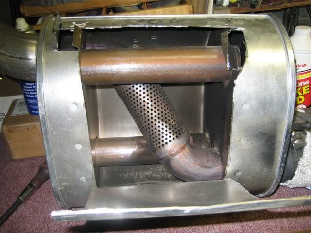
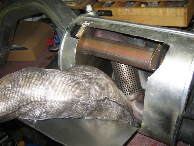
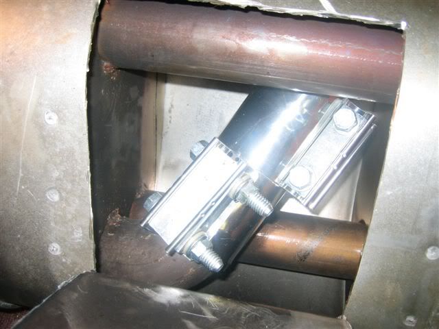
Originally Posted by nag1945
Hello: I had posted a few weeks ago about cutting the original mufflers open to improve sound. One of you guys was kind enough to post a pic of the muffler and diagram of how the muffler works in the open side and the closed side. To bring you up to date if your are interested I have lots of pics and diagrams but have now modified the muffler by removing the glass blanket in the center chamber and sealed the perforated pipe internally with wide SS band clamps and have pics of that. I have welded the mufflers closed and will put on the car next week when I can borrow a lift. Keep in mind the pipe entering the muffler goes down to 2 1/2 inches all the way to the butterfly side. The restricted side of the muffler works on a 1 1/2 inch pipe all the way. But if you add it up its okay. When the fuse is pulled at low rpms the muffler has a resonation from the fiberglas blanket. If any one wants to see the pics email at rgreisberg@optonline.net... I honestly believe for a modification that cost 16 dollars I will have a good sounding muffler and still have a somewhat quiet one when I want it.
Originally Posted by nag1945
It is restricted that way and the car actually doesn't mind the detune under 3500 its good torque management. Thats why it opens at 3500 RPM and has a 1 1/2 inch pipe and a 2 1/2 inch pipe in combo. Here in NY area driving this car in bumper to bumpe traffic especially creeping up a hill at one mile an hour the engine surges the clutch chatters and the engine really hates it so the restricted muffler probably helps.
Originally Posted by MAJ Z06
The pics:

Last edited by LTC Z06; 06-19-2006 at 12:41 AM.
08-06-2006, 12:14 PM
#48
Get Some!
Thread Starter
Originally Posted by Short-Throw
I decided to take some pics of the clutch fluid reservoir while I changed my fluid today. I know there have been a few pics posted over the past year, but I figured a few more wouldn't hurt and would be a good review.
Thanks again to Ranger for the heads-up.
Here is his post from March 3rd, 2006: Click Here For Ranger's Tips
The first pic here shows everything you need. This is a great maintenance job as it requires no tools!
The clutch fluid reservoir is located to the right of windshield washer fill and just below the Master Cylinder as noted in the pic below.
Also shown is the syringe I used to extract the fluid and the DOT4 Brake and Clutch Fluid from Chevy.....Part Number 88958860 as first noted by Ranger.

This next pic shows the cap removed with all the gunk on it.

The rubber insert is removable.
This pic shows the cap and insert cleaned.

Here's the cap and rubber compressed back into place ready to vacuum again.

It takes only a minute or so to extract the fluid. I put towels down like it was surgery just to keep that paint eating sludge away from the car.

After syphoning what you can, just stick a paper towel in, wipe and mop out the remaining fluid. Here is a pic of the reservoir cleaned out.

There is a low and high fill line on the outside of the reservoir. Fill to appropriate level and replace cap.
Like Ranger said, it only takes about three minutes but remember, Ranger is faster than most of us, so it may take you 3.1 minutes!
I hope this helps.
Mike
Thanks again to Ranger for the heads-up.
Here is his post from March 3rd, 2006: Click Here For Ranger's Tips
The first pic here shows everything you need. This is a great maintenance job as it requires no tools!
The clutch fluid reservoir is located to the right of windshield washer fill and just below the Master Cylinder as noted in the pic below.
Also shown is the syringe I used to extract the fluid and the DOT4 Brake and Clutch Fluid from Chevy.....Part Number 88958860 as first noted by Ranger.
This next pic shows the cap removed with all the gunk on it.
The rubber insert is removable.
This pic shows the cap and insert cleaned.
Here's the cap and rubber compressed back into place ready to vacuum again.
It takes only a minute or so to extract the fluid. I put towels down like it was surgery just to keep that paint eating sludge away from the car.
After syphoning what you can, just stick a paper towel in, wipe and mop out the remaining fluid. Here is a pic of the reservoir cleaned out.
There is a low and high fill line on the outside of the reservoir. Fill to appropriate level and replace cap.
Like Ranger said, it only takes about three minutes but remember, Ranger is faster than most of us, so it may take you 3.1 minutes!
I hope this helps.
Mike
09-13-2006, 02:45 PM
#49
Get Some!
Thread Starter
4000K bulbs
http://forums.corvetteforum.com/show....php?t=1493014
6000K bulbs
http://forums.corvetteforum.com/show....php?t=1526304
Some common examples.
1700 K: Light of matches
1850K : a candle
2800 K: tungsten lamp (ordinary household bulb whatever its power)¨
3350K : studio "CP" light
3400 K: studio lamps, photofloods,
5000 K: Daylight°
5500 K: average daylight, electronic flash (can vary between manufacturers)
5770 K: effective sun temperature
6420 K: Xenon arc lamp
6500 K: Daylight°
9300 K: TV screen (analog)
28000 - 30000 K: a lightning bolt [1]
A regular 100 watt light bulb is about 2800 Kelvin, sunlight is 5000 Kelvin and the light on an overcast day is 6500 Kelvin or higher.
Last edited by LTC Z06; 11-29-2006 at 12:34 PM.
09-23-2006, 12:35 PM
#50
Get Some!
Thread Starter
This is on a C6, ensure your fluids etc. are C6 Z06 specific, but the basics of the procedure should be the same:
DIY � Rear Axle / Differential oil change, with pics � for FAQ
http://forums.corvetteforum.com/show....php?t=1497063
DIY � Rear Axle / Differential oil change, with pics � for FAQ
http://forums.corvetteforum.com/show....php?t=1497063
Originally Posted by Vet
DIY: Changing the oil in a base C6 rear axle / differential
Overall it�s very easy, a DIY is not even really necessary, but if it�s your first time, this will at least give you an idea of what to expect. This DIY is for base C6s only. Z06s have differential coolers (base C6's do not) and require a bit more effort. Z06s and export vehicles have different axle oil capacities than the base C6 as well.
First, if possible, run the car a while to get the axle oil warm. I ran the car about 40 miles. When I got back, the axle case was quite hot to the touch. Even after 20 minutes or so, the mufflers were cool but the axle case was still hot. With this in mind, it is probably a good idea to wait a bit (maybe a half hour) until the exhaust system cools down so you do not severely burn yourself� the axle will still be warm.
You�ll need to get the car up off the ground a bit as in photos, but keep car LEVEL. First choice would be to use a real lift. Second choice, back the car up on Race Ramps and then jack the front end in order to level the car. Last choice (most laborious), jack the car from both front and rear.

Since you need to access the rear axle from the rear, you cannot block the rear with a jack. I had initially tried to use my 4-point jack system, but was not able to access the axle plugs with the rear jack and cross member in the way. I had to add stands under the rear puck locations and then remove the rear jack and cross member. I then added two extra screw jacks under the rear �preferred� jacking locations for extra support and safety. This worked out fine. But next time I think I�ll try backing up on ramps� would be easier.
The axle case has two plugs that must be removed� a fill plug and drain plug. The fill plug is on the rear vertical side of the case, the drain plug is on the bottom horizontal side of the case. Both plugs exist on the right half of the case (passenger side). Both plugs are identical in size / type.


Put some cardboard down on the floor and have some rags on hand as you will inevitably spill / splash some oil. Place a drain pan directly under the drain and fill plugs.
Clean the areas around both plugs. Using a 3/8� drive swivel arm socket wrench and 10mm allen socket of about 1 � �� total length (as shown), loosen and remove the fill plug. There are different ways of accessing this plug but the photos show one method that seems to work well and is easy. Note in the photos that the socket wrench handle extends down through the middle of the aluminum cross member. Some oil may start to drip out. If the plug should be tight, use a piece of pipe over your socket handle for leverage. Both my plugs did not require much effort to loosen� pipe was not needed.


Next, loosen and remove the drain plug. The oil will come blasting out and may splash in the pan so shield your face. Allow the axle to drain for a while. Mine was still dripping 12 hours later.
Clean the drain plug and area around the drain hole and install drain plug. Torque to 35 Nm or 26 lb/ft. I chose to torque by hand� basically just got it nice and snug. Do not overtighten. You could get a torque wrench on the drain plug easily if you wanted, but not on the fill plug. If you are not sure about the torque �feel�, use a torque wrench on the drain plug in order to get a good �feel� for what it should be, then do your best to apply that same �feel� to the fill plug using your regular socket wrench.
Time to refill the axle. Read the latest GM TSB regarding rear axle chatter to determine which GM gear oil you should be using. In sum, if you are experiencing chatter and your clutch packs / plates have NOT yet been changed, use GM part # 89021669 (non-synthetic) gear oil and 4 oz of GM part # 01052358 friction modifier additive - this is different than what the shop manual calls for. If you are not experiencing chatter, or if your clutch packs have just been changed, use GM part # 12378261 synthetic gear oil and 4 oz of the same additive described above - this IS what the shop manual calls for.
I used the non-synthetic oil below due to a cold chatter problem.

The manual calls for 1.69 quarts (54 ounces) of fluid. The non-synthetic GM gear oil recommended by the Chevrolet TSB for chatter conditions prior to clutch pack change comes in 23 ounce bottles (pictured below). The additive comes in a 4 ounce bottle. You will need a minimum of three 23oz bottles of gear oil, and one full 4 oz bottle of additive, but have at least four bottles of gear oil on hand, reasons below. To be super safe, you may want to have additional bottles of gear oil and additive on hand in case you spill� you�ll most likely be changing the axle oil again anyway, so may as well stock up in advance.
Since you will not be able to get the oil bottles higher than the fill hole, you must pump or squeeze the oil up into the hole.
The GM oil bottles come with extra pointed nozzle caps and a short piece of clear tubing. I found this set up to be too short and too small a diameter, plus after a while the nozzle gets oily and the hose starts slipping off the nozzle no matter what you do. One solution is to buy an aftermarket fill tube at the local auto store. The product I found (at Pep Boys) is made by Hopkins Manufacturing, called a �FloTool�� it threads right onto the GM oil bottles and has a 12� long section of clear tubing attached� twice as long and larger diameter than what you get with the GM oil bottle. This FloTool fit really nice and made the oil fill a breeze.

Insert the tubing into the fill hole of the axle holding the gear oil bottle up between the mufflers and squeeze the bottle. You will see the oil flow through the tube and into the axle. One headache though is that you can only get about half the contents of the bottle into the axle even if you squeeze / crush the bottle as hard as you can� you can only squeeze about 14 oz out of that 23 oz bottle at once� so you have to refill the bottle and do it again about 5 or more times. This is the main reason to have at least 4 bottles of gear oil on hand� because you can never get ALL the gear oil out of the bottle when just squeezing the bottle. I guess you�d need a pump of some type to really empty the entire bottle into the axle... but not necessary because whatever oil does not make it into the axle can be saved for the next fluid change.

Note: I am holding the bottle upside down in the photo � was just posing in that shot � bottle nozzle should be as low as you can get it with relation to the rest of the bottle.
I started by putting about 10 ounces of oil in the axle. I then added the entire 4 oz bottle of additive to a bottle of gear oil that had about 13 ounces left in it� shook it well� then added as much of this mix as possible to the axle. Then just kept refilling this SAME bottle with gear oil, shaking and adding it to the axle until oil started dripping out of the axle oil fill hole. I then allowed the oil to drip out for a bit to make sure the axle was not overfull. Reinstall fill plug. Again, make sure car is level.
The problem with doing the above is that I may not have gotten 100% of the additive into the axle on this fill since some may have been left in the gear oil bottle. This is because it is impossible to completely empty the gear oil bottle into the axle. Since more and more gear oil was added to that one bottle, I pretty much flushed almost all the additive out of that bottle and into the axle, but still� to really make sure to get the entire 4 oz of additive into the axle, it would be best to just add it directly without pre-mixing. I will probably try this next time. The additive bottle comes with a squirt tip so you might just be able to squirt the additive directly into the axle from the additive bottle without any adapters, hoses, etc. But not sure� have yet to try it.
Though the manual calls for 1.69 quarts (54 ounces), it seems that my axle took a bit more than this� closer to about 62 ounces or so (or 1.94 quarts), estimated. In any case, just make sure to have at least 64 ounces of oil on hand, in addition to the 4 oz of additive. Remember too, you will drip / spill some� and some will remain in your FloTool, etc.
I installed the plugs without any sealer or Teflon, etc� so far no leaks. The plugs seem to have some type of thin gasket / washer attached so they may not need help in any case. If help IS needed, a SMALL amount of silicon sealer on the threads would probably do the trick� but be sparing because otherwise when you go to remove the plugs next time, you�ll have a bunch of silicon sealer debri in the holes, makes a mess and could find it�s way into the axle.

Above is just one way to change the rear axle oil on a C6. If anyone has any other tips, tricks etc, please add to this thread. Also, I must thank the forum and its members for much of the info in this DIY post!
Overall it�s very easy, a DIY is not even really necessary, but if it�s your first time, this will at least give you an idea of what to expect. This DIY is for base C6s only. Z06s have differential coolers (base C6's do not) and require a bit more effort. Z06s and export vehicles have different axle oil capacities than the base C6 as well.
First, if possible, run the car a while to get the axle oil warm. I ran the car about 40 miles. When I got back, the axle case was quite hot to the touch. Even after 20 minutes or so, the mufflers were cool but the axle case was still hot. With this in mind, it is probably a good idea to wait a bit (maybe a half hour) until the exhaust system cools down so you do not severely burn yourself� the axle will still be warm.
You�ll need to get the car up off the ground a bit as in photos, but keep car LEVEL. First choice would be to use a real lift. Second choice, back the car up on Race Ramps and then jack the front end in order to level the car. Last choice (most laborious), jack the car from both front and rear.
Since you need to access the rear axle from the rear, you cannot block the rear with a jack. I had initially tried to use my 4-point jack system, but was not able to access the axle plugs with the rear jack and cross member in the way. I had to add stands under the rear puck locations and then remove the rear jack and cross member. I then added two extra screw jacks under the rear �preferred� jacking locations for extra support and safety. This worked out fine. But next time I think I�ll try backing up on ramps� would be easier.
The axle case has two plugs that must be removed� a fill plug and drain plug. The fill plug is on the rear vertical side of the case, the drain plug is on the bottom horizontal side of the case. Both plugs exist on the right half of the case (passenger side). Both plugs are identical in size / type.
Put some cardboard down on the floor and have some rags on hand as you will inevitably spill / splash some oil. Place a drain pan directly under the drain and fill plugs.
Clean the areas around both plugs. Using a 3/8� drive swivel arm socket wrench and 10mm allen socket of about 1 � �� total length (as shown), loosen and remove the fill plug. There are different ways of accessing this plug but the photos show one method that seems to work well and is easy. Note in the photos that the socket wrench handle extends down through the middle of the aluminum cross member. Some oil may start to drip out. If the plug should be tight, use a piece of pipe over your socket handle for leverage. Both my plugs did not require much effort to loosen� pipe was not needed.
Next, loosen and remove the drain plug. The oil will come blasting out and may splash in the pan so shield your face. Allow the axle to drain for a while. Mine was still dripping 12 hours later.
Clean the drain plug and area around the drain hole and install drain plug. Torque to 35 Nm or 26 lb/ft. I chose to torque by hand� basically just got it nice and snug. Do not overtighten. You could get a torque wrench on the drain plug easily if you wanted, but not on the fill plug. If you are not sure about the torque �feel�, use a torque wrench on the drain plug in order to get a good �feel� for what it should be, then do your best to apply that same �feel� to the fill plug using your regular socket wrench.
Time to refill the axle. Read the latest GM TSB regarding rear axle chatter to determine which GM gear oil you should be using. In sum, if you are experiencing chatter and your clutch packs / plates have NOT yet been changed, use GM part # 89021669 (non-synthetic) gear oil and 4 oz of GM part # 01052358 friction modifier additive - this is different than what the shop manual calls for. If you are not experiencing chatter, or if your clutch packs have just been changed, use GM part # 12378261 synthetic gear oil and 4 oz of the same additive described above - this IS what the shop manual calls for.
I used the non-synthetic oil below due to a cold chatter problem.
The manual calls for 1.69 quarts (54 ounces) of fluid. The non-synthetic GM gear oil recommended by the Chevrolet TSB for chatter conditions prior to clutch pack change comes in 23 ounce bottles (pictured below). The additive comes in a 4 ounce bottle. You will need a minimum of three 23oz bottles of gear oil, and one full 4 oz bottle of additive, but have at least four bottles of gear oil on hand, reasons below. To be super safe, you may want to have additional bottles of gear oil and additive on hand in case you spill� you�ll most likely be changing the axle oil again anyway, so may as well stock up in advance.
Since you will not be able to get the oil bottles higher than the fill hole, you must pump or squeeze the oil up into the hole.
The GM oil bottles come with extra pointed nozzle caps and a short piece of clear tubing. I found this set up to be too short and too small a diameter, plus after a while the nozzle gets oily and the hose starts slipping off the nozzle no matter what you do. One solution is to buy an aftermarket fill tube at the local auto store. The product I found (at Pep Boys) is made by Hopkins Manufacturing, called a �FloTool�� it threads right onto the GM oil bottles and has a 12� long section of clear tubing attached� twice as long and larger diameter than what you get with the GM oil bottle. This FloTool fit really nice and made the oil fill a breeze.
Insert the tubing into the fill hole of the axle holding the gear oil bottle up between the mufflers and squeeze the bottle. You will see the oil flow through the tube and into the axle. One headache though is that you can only get about half the contents of the bottle into the axle even if you squeeze / crush the bottle as hard as you can� you can only squeeze about 14 oz out of that 23 oz bottle at once� so you have to refill the bottle and do it again about 5 or more times. This is the main reason to have at least 4 bottles of gear oil on hand� because you can never get ALL the gear oil out of the bottle when just squeezing the bottle. I guess you�d need a pump of some type to really empty the entire bottle into the axle... but not necessary because whatever oil does not make it into the axle can be saved for the next fluid change.
Note: I am holding the bottle upside down in the photo � was just posing in that shot � bottle nozzle should be as low as you can get it with relation to the rest of the bottle.
I started by putting about 10 ounces of oil in the axle. I then added the entire 4 oz bottle of additive to a bottle of gear oil that had about 13 ounces left in it� shook it well� then added as much of this mix as possible to the axle. Then just kept refilling this SAME bottle with gear oil, shaking and adding it to the axle until oil started dripping out of the axle oil fill hole. I then allowed the oil to drip out for a bit to make sure the axle was not overfull. Reinstall fill plug. Again, make sure car is level.
The problem with doing the above is that I may not have gotten 100% of the additive into the axle on this fill since some may have been left in the gear oil bottle. This is because it is impossible to completely empty the gear oil bottle into the axle. Since more and more gear oil was added to that one bottle, I pretty much flushed almost all the additive out of that bottle and into the axle, but still� to really make sure to get the entire 4 oz of additive into the axle, it would be best to just add it directly without pre-mixing. I will probably try this next time. The additive bottle comes with a squirt tip so you might just be able to squirt the additive directly into the axle from the additive bottle without any adapters, hoses, etc. But not sure� have yet to try it.
Though the manual calls for 1.69 quarts (54 ounces), it seems that my axle took a bit more than this� closer to about 62 ounces or so (or 1.94 quarts), estimated. In any case, just make sure to have at least 64 ounces of oil on hand, in addition to the 4 oz of additive. Remember too, you will drip / spill some� and some will remain in your FloTool, etc.
I installed the plugs without any sealer or Teflon, etc� so far no leaks. The plugs seem to have some type of thin gasket / washer attached so they may not need help in any case. If help IS needed, a SMALL amount of silicon sealer on the threads would probably do the trick� but be sparing because otherwise when you go to remove the plugs next time, you�ll have a bunch of silicon sealer debri in the holes, makes a mess and could find it�s way into the axle.
Above is just one way to change the rear axle oil on a C6. If anyone has any other tips, tricks etc, please add to this thread. Also, I must thank the forum and its members for much of the info in this DIY post!
Originally Posted by Vet
Updated - latest TSB - 9/08/06
Just for quick reference, here�s the most recent axle chatter TSB:
Subject: Rear Axle Chatter Shudder on Turns - keywords bind differential #PIP3559A - (09/08/2006)
Models: 1999-2007 Chevrolet Corvette
2004-2006 Cadillac XLR
2006-2007 Cadillac XLR-V
------------------------------------------
This PI is being superseded to update recommendations, models and years.
Please discard PIP3559.
------------------------------------------
The following diagnosis might be helpful if the vehicle exhibits the symptom(s) described in this PI.
Condition/Concern:
Rear axle chatter or shudder on turns on Chevrolet Corvette and Cadillac XLR.
Recommendation/Instructions:
If this is the first complaint for this condition flush and fill the rear axle with mineral based lubricant P/N 89021669 (in Canada 89021670) gear lube and 4 ounces of the friction modifier additive P/N 01052358 (in Canada 992694).
If this is a repeat complaint or the condition persists after the flush and fill, replace the right and left rear axle clutch packs following published service procedures.
After clutch pack replacement use 1.6 l (1.69 qt) synthetic axle lubricant GM P/N 12378261 (Canadian P/N 10953455). and 4 ounces of the friction modifier additive P/N 01052358 (in Canada 992694).
Note: 2006 Z06 equipped vehicles require 2.55 l (2.70 qt) synthetic axle lubricant GM P/N 12378261 (Canadian P/N 10953455) and approximately 190 ml (6.4 oz) limited-slip differential lubricant additive GM P/N 1052358 (Canadian P/N 992694).
Note 2: Export vehicles use 2.01 l (2.12 qt) synthetic axle lubricant GM P/N 12378261 (Canadian P/N 10953455) and approximately 150 ml (5.1 oz) limited-slip differential lubricant additive GM P/N 1052358 (Canadian P/N 992694).
Once the axle fluid has been changed the car must be driven in 8 - 10 SLOW figure eights to work the fluid between the clutch plates.
Note 3: PRIOR TO INSTALLING THE FRICTION MODIFIER ADDITIVE FOR EITHER OF THE ABOVE REPAIRS THE BOTTLE MUST BE SHAKEN VIGOROUSLY FOR AT LEAST 1 MINUTE TO MIX THE ADDITIVE THOROUGHLY.
---------------------------
Originally Posted by Vet
A few other bits of interesting info:
*Member vetteshop stated: ��in the past,I have replaced a bunch of clutch packs in the C5's, they have the same issue. Upon inspection of the removed clutch packs, they do not fail, they look brand new with no evidence of wear or damage. The issue seems to be a varnish buildup on the plates that causes binding, resulting in the noise when turning. This is why replacing the fluid (with new additive) may only temporarily cure the problem. The problem is the design of the rear differential. Caprice's and Camaro's with posi rears have had the same issue for years. The difference on the Corvette is that there is not a cover that you can remove to clean the clutch packs, such as every other conventional posi rear end. The only way to clean the clutch packs is to remove the rear from the vehicle and completely disassemble it. One may as well install new clutch packs after going through all that trouble��
*Member calemasters stated: ��Original axle clutch plates were fiber. New plates are carbon� I believe BG production changed to the carbon plates in late December of 2005� I spoke to one of the Getrag engineers (he used to be on this board) but he was not clear to why the grind chatter occurred with the fiber plates. Just that the carbon plates fix this condition��
*Memeber mbonness put up this interesting poll regarding axle chatter and build date: http://forums.corvetteforum.com/show...ight=axle+poll
---
01-19-2007, 09:06 PM
#51
Get Some!
Thread Starter
http://forums.corvetteforum.com/show....php?t=1602281
I get asked this a lot so I thought it would be helpful to post:
1) The only way to properly check (and know where you are in the travel) is
to use a special checking lifter or completely compress a stock lifter.
a) Checking lifter consists of a lifter that has been disassembled
to install shims that lock the plunger at the top of travel in the lifter body.
If using this method you would add length to the checking pushrod to put the
final pushrods into the middle of travel of the plunger.
b) Using a stock lifter, you must make certain that you have pumped
all the oil out of the lifter. To do this leave it at valve full open (highest
spring load) for a while with an indicator on the pushrod side of the
rocker. Watch to see when the indicator stops moving (when the plunger is
fully compressed in the lifter body). Once you have compressed the lifter
rotate the engine to close the valve, extend your checking pushrod to full
length. Using this method you will subtract length from your checking
pushrod to put the final pushrods into the middle of travel of the plunger.
2) Typical plunger travel on Gen 3/4 lifters is 0.150 - 0.200 depending on
the manufacturer, year, etc. We recommend 0.075-0.100" from the bottom of
travel (using method 'b' described above) or 0.075 from the top of travel
(using method 'a' described above). That will generally put you close to
the middle of travel. While there are many different strategies for where
to put the plunger, for street use we strongly suggest that near the middle
of travel is the safest for durability.
3) The more precise method of checking is 'a' because you are not guessing
that you got all the oil out.
With this though, I do have to make the disclaimer that since we are not doing the assembly ourselves, we cannot be responsible for any misunderstandings. We recommend assembly by experienced professionals to avoid possible issues.
__________________
01-22-2007, 09:13 AM
#52
Get Some!
Thread Starter
Originally Posted by Congaman
Ok, Todd here they come.
All video were made on the Koenigsegg test track in September 2006 by invitation of M5Board.com.
In all races I did the same mistake as I started in 2ned gear. At the time I thought this was a good idea as I wanted to avoid tire slip and hiting the rev limiter. When I understood my mistake it was to late as the day was over. This year I will do better!
C6 Z06 Vs M6 (Both cars are stock)
http://www.youtube.com/watch?v=ovZWaOYMBkE
C6 Z06 Vs. Kelleners M5 (M5 tuned to 550 Hp. Later the same day it beat the Porsche 997 TT)
http://www.youtube.com/watch?v=iEcfesmyRbE
C6 Z06 Vs. Ferrari 430 F1 (the Ferrari had an aftermarket exhaust)
http://www.youtube.com/watch?v=TAyx3gwqXn0
02-23-2007, 11:39 AM
#53
Get Some!
Thread Starter
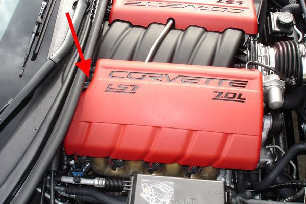
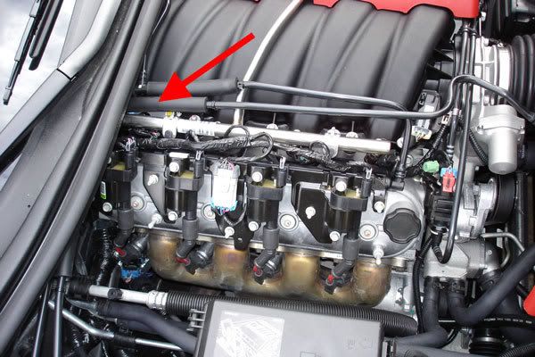
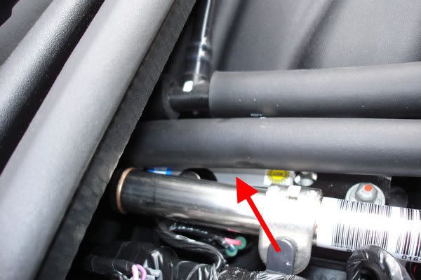
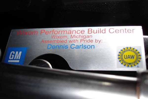
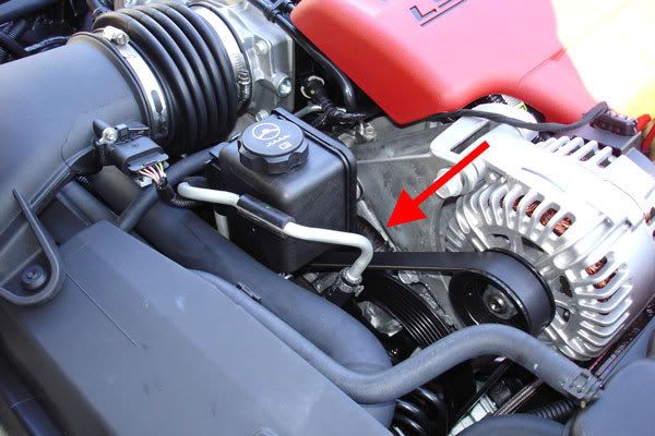
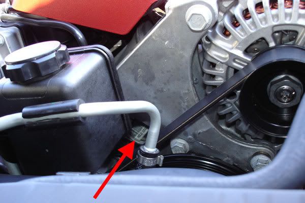
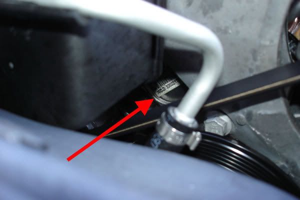
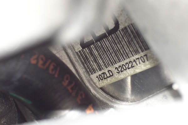 09-12-2007, 11:34 PM
#55
Team Owner


 12-10-2008, 11:00 AM
#56
Team Owner
08-02-2011, 02:23 PM
#57
Heel & Toe


Member Since: Feb 2009
Posts: 21
Likes: 0
Received 0 Likes
on
0 Posts
Is it true on the 2009 ZO6 when filling raditor reserve that you have to do more than top it off. I have heard that way doesn't completely fill it and you car can overheat very esay. Just put new motor in drove on highway, no problems. Yesterday just driving it it heated over several times. anyone else had similar problem
03-02-2016, 07:42 AM
#58

A lot of good information here thanks everyone.


