
[Z06] My valve guides are shot. I'm in warranty and don't know what to do.
 01-21-2013, 12:01 PM
#21


How many miles where on her when purchased?
 01-21-2013, 12:02 PM
#22


Hi Erik,
Just want to do a sanity check here. I thought I saw you dial indicator move to 15 on the scale, from what I can see the increments are listed as 0.001 inches. That would make your measured valve slop 0.015 or fifteen thousanths. That's still outta spec but an order of magnitude better.
I'm no expert but the rocker arm wear doesn't appear too bad for that much slop...Maybe other can weigh in on this and qualitatively provide some wear comparison descriptions.
THX
B
01-21-2013, 12:47 PM
#23

Almost worth the piece of mind to send your heads off or go with an aftermarket set of heads. I am curious as to the route you take. I would have a hard time putting the boost to it through stock heads. I purchased my Z with the thoughts of buying a car and leaving it stock because of the power the Z's make, however sadly thats not going to be the case. I will be pulling the heads and either sending them in WCCH or purchasing aftermarket heads and doing a mild cam swap at the same time.
01-21-2013, 12:48 PM
#24
Tech Contributor
Member Since: Oct 1999
Location: Charlotte, NC (formerly Endicott, NY)
Posts: 40,078
Received 8,919 Likes
on
5,328 Posts

So I am in possession of John_G famous tool to measure geometry.
I've been traveling back and forth between TN and NC before I go on extended travel outside the Country.
First I pulled the spark plugs and most of them looked dry. There were two that had some oil on the threads.
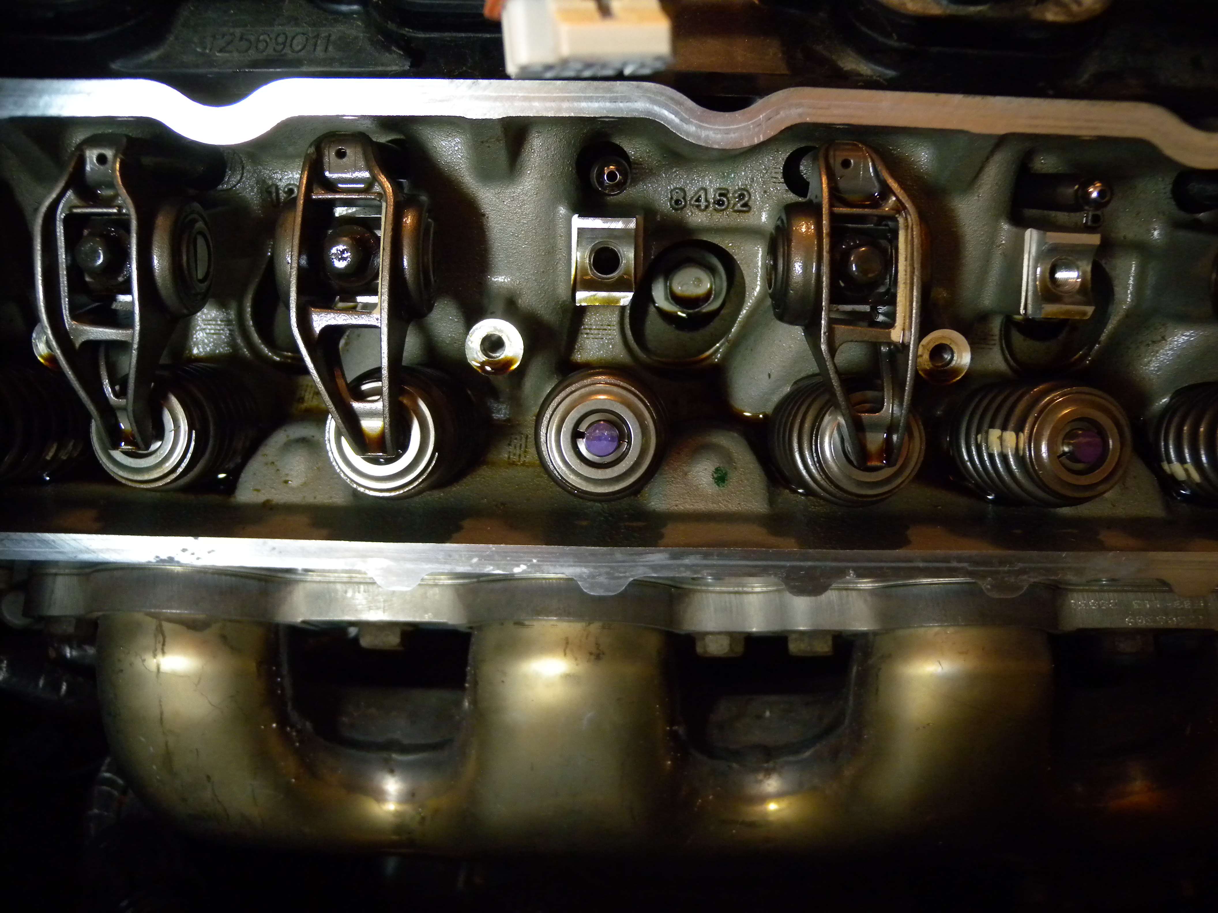
Then after removing the rockers I thought things were looking good, as the wear pattern seemed to be rectangular. But, I couldn’t stop there, I had to measure the actual clearance because I want to modify the engine. I bought am Edelbrock E-Force last year, and have been holding off on the install because of these valve issues. Good thing I did.
Since the exhaust valves seen to have the most wear, I removed the #1 exhaust spring, lifted the valve off the seat a little and measured the clearance. .150” Yes that is correct. You can visibly see the movement in the valve. You don't need a dial gauge to tell you that it's shot.
Then I move on to #5, and check the intake. Yep, don't need a dial gauge here either.
#5 exhaust is next
At this point, I really didn’t want to check any more, but thought I would check the other side, so I check cylinder #4
Yep. Its shot too at .100"
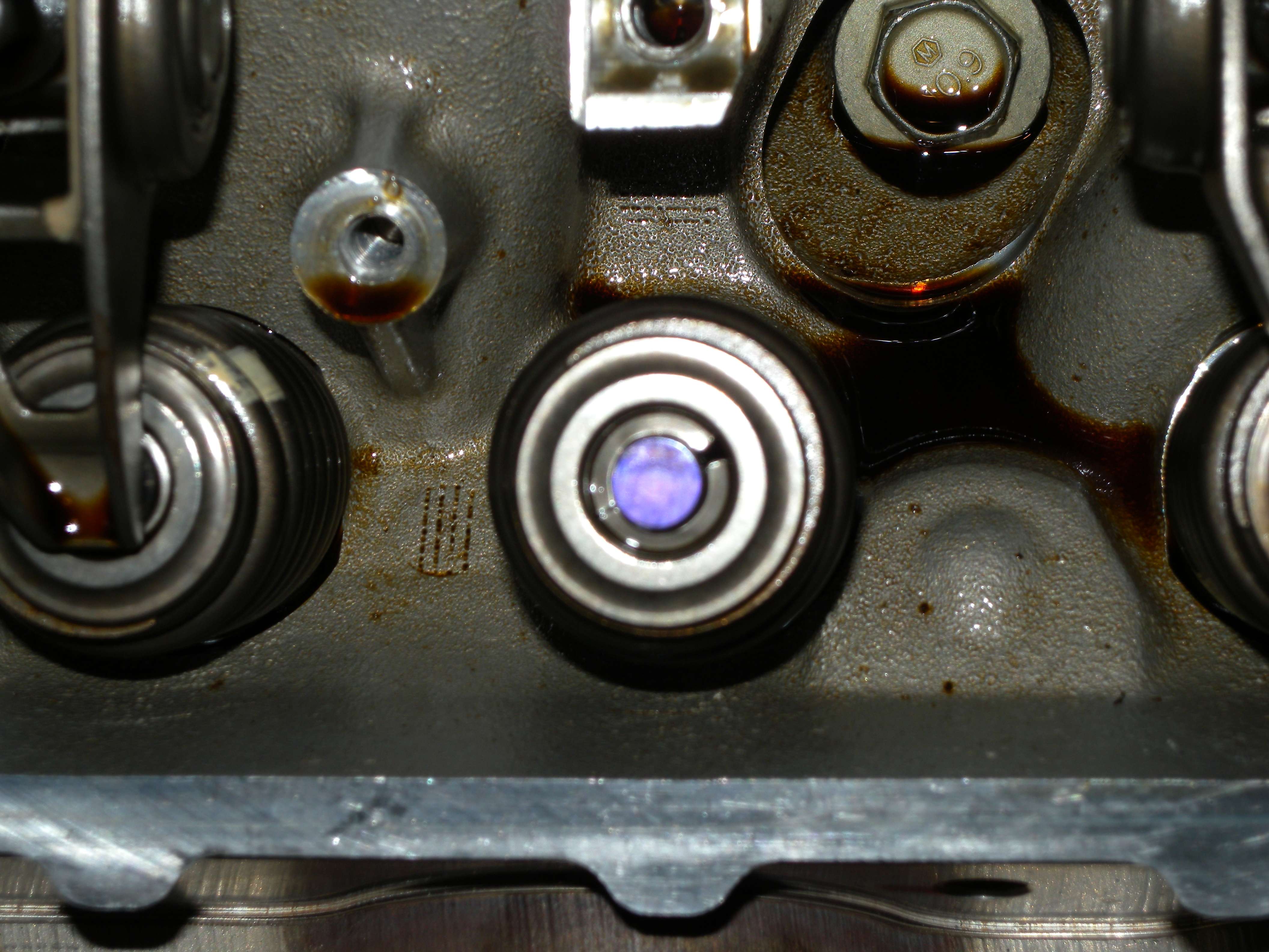
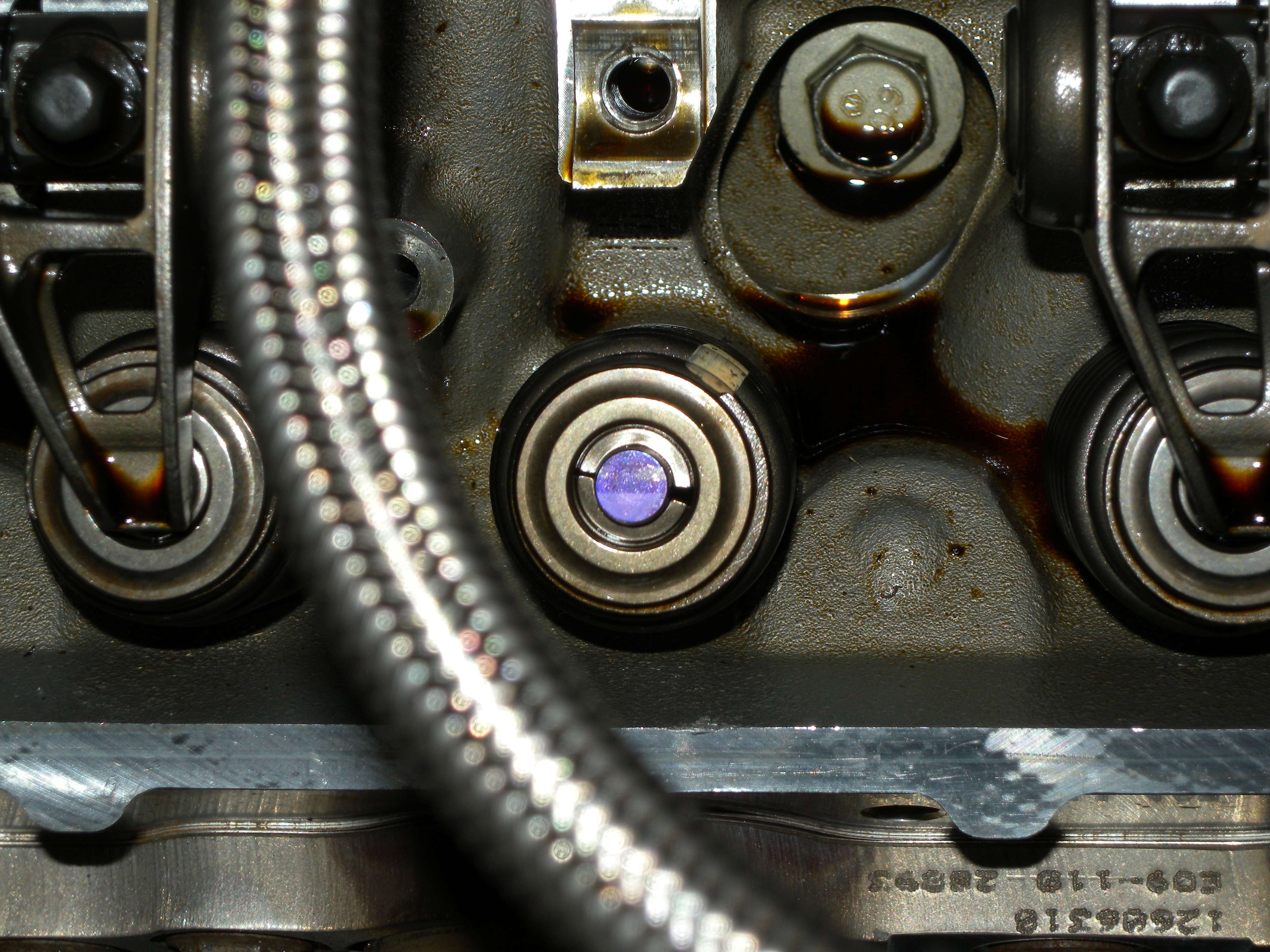
And a few pictures of the wear pattern on the valve stems. Looks like a good wipe pattern for the most part.
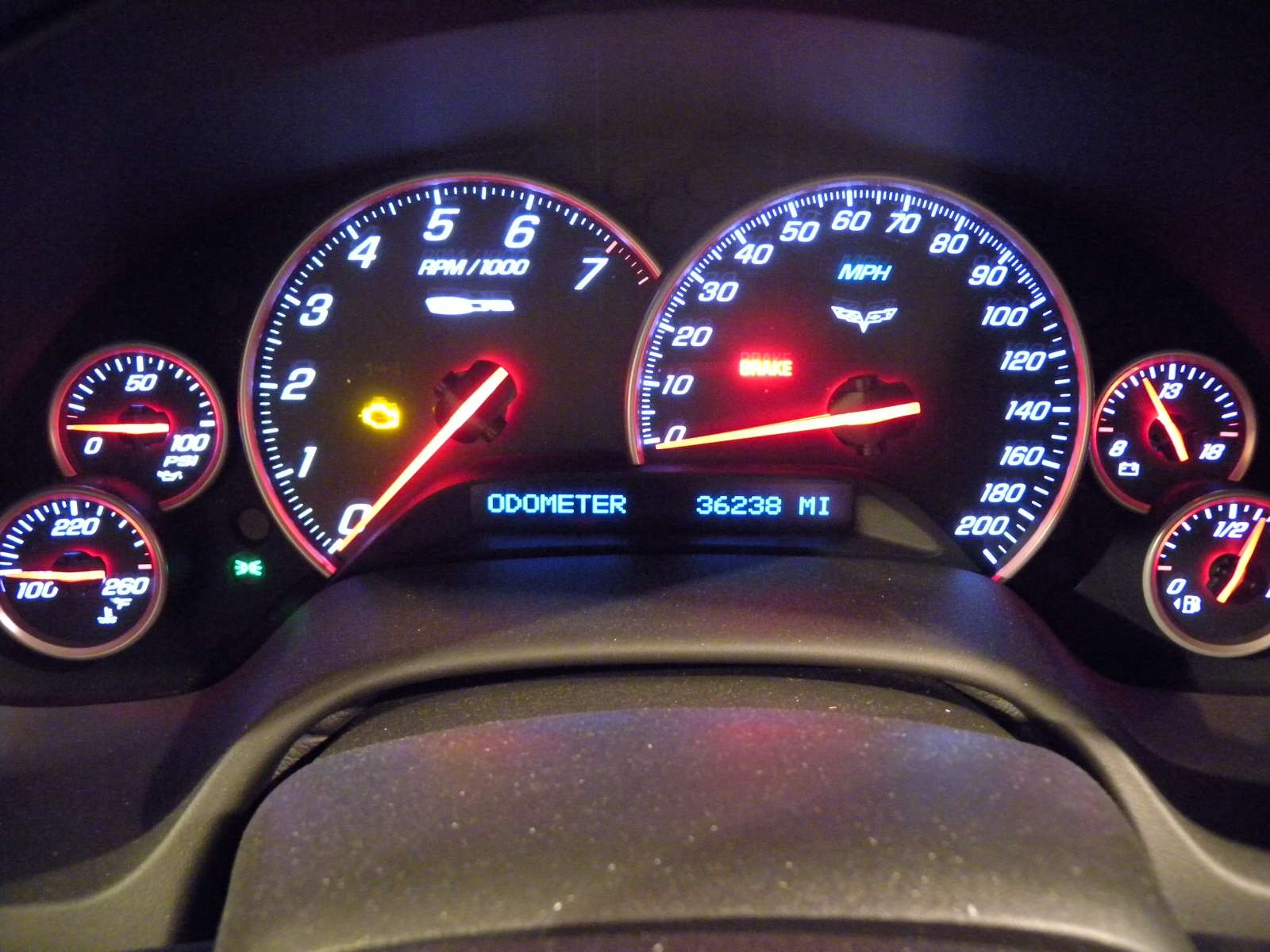
So with 36238 miles, what do I do?
I'm still in my warranty window of 4/48 for a CPO. But haven’t had any good experience with a dealer doing any major repair. That’s another threat in itself. Do I take the chance of some kid doing a hack job repair at the dealer, or should I just embrace the suck, and sent my heads off for repair, and have the peace of mind that it is done right?
BTW, thanks to John_G. I wouldn’t have started this unless I had the tool to measure my geometry, which measured good, by the way.
I've been traveling back and forth between TN and NC before I go on extended travel outside the Country.
First I pulled the spark plugs and most of them looked dry. There were two that had some oil on the threads.
Then after removing the rockers I thought things were looking good, as the wear pattern seemed to be rectangular. But, I couldn’t stop there, I had to measure the actual clearance because I want to modify the engine. I bought am Edelbrock E-Force last year, and have been holding off on the install because of these valve issues. Good thing I did.
Since the exhaust valves seen to have the most wear, I removed the #1 exhaust spring, lifted the valve off the seat a little and measured the clearance. .150” Yes that is correct. You can visibly see the movement in the valve. You don't need a dial gauge to tell you that it's shot.
Then I move on to #5, and check the intake. Yep, don't need a dial gauge here either.
#5 exhaust is next
At this point, I really didn’t want to check any more, but thought I would check the other side, so I check cylinder #4
Yep. Its shot too at .100"
And a few pictures of the wear pattern on the valve stems. Looks like a good wipe pattern for the most part.
So with 36238 miles, what do I do?
I'm still in my warranty window of 4/48 for a CPO. But haven’t had any good experience with a dealer doing any major repair. That’s another threat in itself. Do I take the chance of some kid doing a hack job repair at the dealer, or should I just embrace the suck, and sent my heads off for repair, and have the peace of mind that it is done right?
BTW, thanks to John_G. I wouldn’t have started this unless I had the tool to measure my geometry, which measured good, by the way.
Bill
Last edited by Bill Dearborn; 01-21-2013 at 12:52 PM.
01-21-2013, 01:58 PM
#25
Race Director

I will be replacing my heads with PRC 265cc LS7s and maybe down the road I can make the measurements on mine. I will be interested to see what John comments about your measurements.
01-21-2013, 02:21 PM
#26
Safety Car


I'd like to perform this procedure on my 2007 Z06 and document the results as you have.
I understand the down to the point where I get to the valve springs and plugs removed. I've R&R the heads on a C5, so I'm familiar with the process, but I R&R'ed the valves/seals/springs with the head off the car.
1) What tool(s)/procedure did you use to compress the valve spring?
2) How did you keep the valve from falling:
a) when you were wiggling (you mentioned 'wrapped' valves to keep them from falling?)
b) when you re-installed the spring.
3) Is the measurement tool one you made or bought?
Thanks in advance and I hope to perform these tests soon. The more of us that do, the more proof we will have that this ISN'T HYPE.
01-21-2013, 09:10 PM
#27
Drifting

I am making arrangements to have the wiggle test done on my 09Z that just turned 30k miles. Bone stock except for a set of 20's. Not tracked at all. Dealership said couple hours labor. If bad, warranty will pay and a new set of heads. Probably will happen some time this week.
 01-22-2013, 12:27 AM
#30
Burning Brakes


08-06-01-019: Rattle/Tapping Type Noise Heard Under Hood (Diagnose and Replace Engine Oil Tank Transfer Tube Seal (O-Ring)) - (Aug 13, 2008)
Subject: Rattle/Tapping Type Noise Heard Under Hood (Diagnose and Replace Engine Oil Tank Transfer Tube Seal (O-Ring))
Models: 2006-2009 Chevrolet Corvette Z06
2009 Chevrolet Corvette ZR1 with 6.2L or 7.0L Engine (VINs R, E -- RPOs LS9, LS7)
Condition
Some customers may comment on a rattle or tapping type noise that is heard under the hood at just above idle, usually 1200 to 2200 RPM. In some cases, this noise may also be heard on the inside of the vehicle and be more pronounced on the passenger side.
Cause
This noise may be caused by the internal transfer tube in the engine oil tank hitting the inside of the tank cover. The seal (o-ring) that secures the tube in place may split and slide down the tube allowing the tube to be loose.
Correction
Diagnose the noise by raising the vehicle on a hoist and holding the throttle at about 1500 RPM to duplicate the condition.
Use a stethoscope or chassis ears and place them on the side of the engine oil tank. If the noise is detected, perform the procedure outlined below. If the noise is not detected, continue following published diagnostics in SI.
Remove the engine oil tank from the vehicle. Refer to the Oil Tank Replacement procedure in SI.
Remove the eight bolts that secure the tank top.
Separate the tank. Check the seal (o-ring) for proper position and damage. Replace the seal (o-ring) if damaged with P/N 24576940.
Reinstall the tank top and secure with the eight bolts.
Install the engine oil tank into the vehicle.
Refer to the Oil Tank Replacement procedure in SI.
01-22-2013, 09:06 AM
#31
Safety Car
Does anyone have an example of the oil tank ticking? I would think it would not be in the same "time" as valvetrain noise and not increase linearly with RPM.
01-22-2013, 09:52 AM
#32
Melting Slicks


Thread Starter
Eric,
You don't have the numbers to know if your geometry is good or bad. You have consistent measurements but they may be consistently bad. I need you to send the numbers to me. I have an Excel spread sheet with good and bad measurements.
I see brown crescents and round edges on the wear marks on the rockers. Both are indicative of bad geometry. As oily as two of those plugs are, the seals of those cylinders are shot as well.
 John
John
You don't have the numbers to know if your geometry is good or bad. You have consistent measurements but they may be consistently bad. I need you to send the numbers to me. I have an Excel spread sheet with good and bad measurements.
I see brown crescents and round edges on the wear marks on the rockers. Both are indicative of bad geometry. As oily as two of those plugs are, the seals of those cylinders are shot as well.
JohnUPDATE: I spoke with John yesterday, and my numbers confirmed that my heads fall in the range with bad geometry. I was under the impression that if all the numbers were the same, that they were good. However John has a chart with several measurements to compare against good heads.
No, I purchased it Certified Pre-Owned in 2011
19500 when I purchased it in July 2011. .
Hi Erik,
Just want to do a sanity check here. I thought I saw you dial indicator move to 15 on the scale, from what I can see the increments are listed as 0.001 inches. That would make your measured valve slop 0.015 or fifteen thousanths. That's still outta spec but an order of magnitude better.
I'm no expert but the rocker arm wear doesn't appear too bad for that much slop...Maybe other can weigh in on this and qualitatively provide some wear comparison descriptions.
THX
B
Just want to do a sanity check here. I thought I saw you dial indicator move to 15 on the scale, from what I can see the increments are listed as 0.001 inches. That would make your measured valve slop 0.015 or fifteen thousanths. That's still outta spec but an order of magnitude better.
I'm no expert but the rocker arm wear doesn't appear too bad for that much slop...Maybe other can weigh in on this and qualitatively provide some wear comparison descriptions.
THX
B
I'd like to perform this procedure on my 2007 Z06 and document the results as you have.
I understand the down to the point where I get to the valve springs and plugs removed. I've R&R the heads on a C5, so I'm familiar with the process, but I R&R'ed the valves/seals/springs with the head off the car.
1) What tool(s)/procedure did you use to compress the valve spring?
2) How did you keep the valve from falling:
a) when you were wiggling (you mentioned 'wrapped' valves to keep them from falling?)
b) when you re-installed the spring.
3) Is the measurement tool one you made or bought?
Thanks in advance and I hope to perform these tests soon. The more of us that do, the more proof we will have that this ISN'T HYPE.
I understand the down to the point where I get to the valve springs and plugs removed. I've R&R the heads on a C5, so I'm familiar with the process, but I R&R'ed the valves/seals/springs with the head off the car.
1) What tool(s)/procedure did you use to compress the valve spring?
2) How did you keep the valve from falling:
a) when you were wiggling (you mentioned 'wrapped' valves to keep them from falling?)
b) when you re-installed the spring.
3) Is the measurement tool one you made or bought?
Thanks in advance and I hope to perform these tests soon. The more of us that do, the more proof we will have that this ISN'T HYPE.
2a) I rotated the cylinder to TDC, which was rather easy since I removed all the spark plugs and you can see when the valves are closed, but when I added compressed air in the cylinder to assist in keeping the valves on the guides the engine rotated to BDC. So I just tired a small zip tie on the valve where the valve locks would be. This is not needed I the cylinder remains at TDC since the valves will only fall about ��.
2b) The compressed air held the valves in place.
3) The "tool" was made by John_g_46
No valve train noise that was noticeably out of the ordinary. I will post up a video clip later.
01-22-2013, 10:02 AM
#33
Drifting
Eric
It looks like that on at least 2 of the rockers that the wear pattern almost goes off the corner of the tip. Check the play in the rocker shaft trunion bearings. I will bet you will find they are excessive. Also on the LS7 if you rotate the cylinder to TDC that you are working on you do not need air to remove the valve springs or to check the valves in the guides. Just DO NOT turn the crank until you put the springs back on!!
I would do what z51vett suggest and call Jim Ellis and get it taken care of under warrantee unless you want to void the remainder of your current warrantee.
Mark
01-22-2013, 12:21 PM
#34

I had no issue w/100 PSI air, thru an adapter designed for the purpose, pushing the piston down. What did you use for an air source, Eric? A 3500 PSI bottle of nitrogen?

.
Last edited by Mark2009; 01-22-2013 at 12:24 PM. Reason: sp
01-22-2013, 01:29 PM
#35
Safety Car
1) John included a spring compressor in the kit he sends you, however I have a LSM valve spring compressor that works rather well.
2a) I rotated the cylinder to TDC, which was rather easy since I removed all the spark plugs and you can see when the valves are closed, but when I added compressed air in the cylinder to assist in keeping the valves on the guides the engine rotated to BDC. So I just tired a small zip tie on the valve where the valve locks would be. This is not needed I the cylinder remains at TDC since the valves will only fall about ��.
2b) The compressed air held the valves in place.
3) The "tool" was made by John_g_46
01-22-2013, 11:26 PM
#36
Melting Slicks
Thread Starter
Eric
It looks like that on at least 2 of the rockers that the wear pattern almost goes off the corner of the tip. Check the play in the rocker shaft trunion bearings. I will bet you will find they are excessive. Also on the LS7 if you rotate the cylinder to TDC that you are working on you do not need air to remove the valve springs or to check the valves in the guides. Just DO NOT turn the crank until you put the springs back on!!
I would do what z51vett suggest and call Jim Ellis and get it taken care of under warrantee unless you want to void the remainder of your current warrantee.
Mark
It looks like that on at least 2 of the rockers that the wear pattern almost goes off the corner of the tip. Check the play in the rocker shaft trunion bearings. I will bet you will find they are excessive. Also on the LS7 if you rotate the cylinder to TDC that you are working on you do not need air to remove the valve springs or to check the valves in the guides. Just DO NOT turn the crank until you put the springs back on!!
I would do what z51vett suggest and call Jim Ellis and get it taken care of under warrantee unless you want to void the remainder of your current warrantee.
Mark
I have what I consider significant lateral movement in the rocker arms. I would guess 3/32" from left to right, but do not have any radial movement.


 01-22-2013, 11:31 PM
#37
Melting Slicks
Thread Starter
You will need something to hold the valve against its seat while the locks are being removed, and again while they are being reinstalled.
I had no issue w/100 PSI air, thru an adapter designed for the purpose, pushing the piston down. What did you use for an air source, Eric? A 3500 PSI bottle of nitrogen?
.
I had no issue w/100 PSI air, thru an adapter designed for the purpose, pushing the piston down. What did you use for an air source, Eric? A 3500 PSI bottle of nitrogen?
.
01-23-2013, 06:29 PM
#38
Melting Slicks
Thread Starter
01-23-2013, 07:23 PM
#40
