
DIY: Add NPP Switch - True Manual On/Off Valve Control
 03-31-2015, 09:55 AM
#21
Race Director


Member Since: Feb 2014
Location: Center of the Universe, Alabama
Posts: 12,243
Received 95 Likes
on
41 Posts
Theta,
Please see my attached .jpg scan of my thoughts on using the "add a circuit" for your solderless idea.
You would not need to fabricate the "double" jumper piece. Simply put the original 20 amp NPP fuse in the top slots of the "add a circuit" and plug your single plug lead into the bottom, right side slot of the "add a circuit".
What do you think. I have not purchased an "add a circuit" so I have not verified its' internal wiring.
 03-31-2015, 02:27 PM
#22
Tech Contributor
Thread Starter
Member Since: Jan 2006
Location: Saint Louis MO
Posts: 4,761
Likes: 0
Received 218 Likes
on
110 Posts
St. Jude Donor '14-'15
Great info...great write up.
I had similar thoughts but with one difference, I wanted to keep the relocated 20 amp NPP fuse under the hood and on the +12v side of the wiring coming from the fuse panel. I'm a little **** and my reason being that if the wiring coming into the cabin ever chaffed enough to short to ground, that it would be protected. I'll explain what I mean by "+12v side of the wiring coming from the fuse panel". With the NPP fuse removed and with the car running, you take a volt meter and check each of the two fuse socket pin holes, one of them will measure +12 volts to ground. That's the wire I'd want the new fuse socket to be on.
Again kudos.
I understand what you mean, though - I placed the AGC (or ATM - I will give the choice based on preference) right before the switch for the ease of diagnosis. You're suggesting putting the fuse on the +12v hot from the box before it enters the cabin (and preferably inside the box). This is a very good idea, and as I've not put the fuse info up yet, I believe I will do this for the sake of safety.

Reading your other post now - good stuff.

.
Last edited by Theta; 03-31-2015 at 02:33 PM.
03-31-2015, 02:32 PM
#23
Tech Contributor
Thread Starter
Member Since: Jan 2006
Location: Saint Louis MO
Posts: 4,761
Likes: 0
Received 218 Likes
on
110 Posts
St. Jude Donor '14-'15
Theta,
Please see my attached .jpg scan of my thoughts on using the "add a circuit" for your solderless idea.
You would not need to fabricate the "double" jumper piece. Simply put the original 20 amp NPP fuse in the top slots of the "add a circuit" and plug your single plug lead into the bottom, right side slot of the "add a circuit".
What do you think. I have not purchased an "add a circuit" so I have not verified its' internal wiring.
Please see my attached .jpg scan of my thoughts on using the "add a circuit" for your solderless idea.
You would not need to fabricate the "double" jumper piece. Simply put the original 20 amp NPP fuse in the top slots of the "add a circuit" and plug your single plug lead into the bottom, right side slot of the "add a circuit".
What do you think. I have not purchased an "add a circuit" so I have not verified its' internal wiring.
 03-31-2015, 03:30 PM
#24
Tech Contributor
Thread Starter
Member Since: Jan 2006
Location: Saint Louis MO
Posts: 4,761
Likes: 0
Received 218 Likes
on
110 Posts
St. Jude Donor '14-'15
Now that I've found an additional two sources for the Micro2 Add-A-Fuse, I may eliminate the solder method - it requires more work, tools, and time. In addition, since the fuse will now be located within the box, it actually becomes a bigger pain-in-the-butt than the Add-A-Fuse.
Anyone have thoughts on this? Everyone always wanted soldered connections, but now with Micro2 tap options out there, that route sure looks a lot better...
Anyone have thoughts on this? Everyone always wanted soldered connections, but now with Micro2 tap options out there, that route sure looks a lot better...
03-31-2015, 04:55 PM
#25
Race Director
Member Since: Feb 2014
Location: Center of the Universe, Alabama
Posts: 12,243
Received 95 Likes
on
41 Posts
Now that I've found an additional two sources for the Micro2 Add-A-Fuse, I may eliminate the solder method - it requires more work, tools, and time. In addition, since the fuse will now be located within the box, it actually becomes a bigger pain-in-the-butt than the Add-A-Fuse.
Anyone have thoughts on this? Everyone always wanted soldered connections, but now with Micro2 tap options out there, that route sure looks a lot better...
Anyone have thoughts on this? Everyone always wanted soldered connections, but now with Micro2 tap options out there, that route sure looks a lot better...
I like the lighted switch and the location you chose for it. Looking forward to your final tutorial.
03-31-2015, 05:02 PM
#26
Tech Contributor
Thread Starter
Member Since: Jan 2006
Location: Saint Louis MO
Posts: 4,761
Likes: 0
Received 218 Likes
on
110 Posts
St. Jude Donor '14-'15
AutoZone is just rolling out the Bussmann Micro Add-A-Circuits (not in all stores yet), so it's easier to pick either one or 3 up from Amazon with Prime shipping.
I got caught up in having the switch inside (my gauge fuses are AGC, but a pain to get to), and forgot how easily the existing 20A would be to use. Thanks for taking the time to draw that up - it's always easier for us to draw than it is to write out an explanation... Well, unless it's an equation - though I still normally take a photo of my scribbles, as well.

This has to be the weirdest tutorial for people watching, in that it's changed so much. Thought about bringing it down and re-tooling, but input like this is very much welcome and appreciated.
 03-31-2015, 05:16 PM
#27
Race Director
Member Since: Feb 2014
Location: Center of the Universe, Alabama
Posts: 12,243
Received 95 Likes
on
41 Posts
This might be one more concern. The "tap a fuse" I looked at only had a 10 amp rating.
I get paranoid about putting a 20 amp fuse in a 10 amp rated "tap a fuse".
I get paranoid about putting a 20 amp fuse in a 10 amp rated "tap a fuse".
03-31-2015, 05:20 PM
#28
Tech Contributor
Thread Starter
Member Since: Jan 2006
Location: Saint Louis MO
Posts: 4,761
Likes: 0
Received 218 Likes
on
110 Posts
St. Jude Donor '14-'15
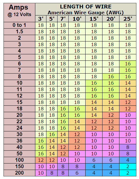
Checked with Bussmann, and then looked at the other taps online. 25A is the actual maximum. The lead attached is a 16AWG, and 16AWG is rated for 20A at up to 10 feet in 12V circuits (25A @ 6ft). Past that, it drops to 15A at 16ft, etc. We'll be using 6-7 feet of wire after the cutting (starting out with 10, and trimming way down), so we're well within the guidelines of safety.
Since they didn't use 14ga, this was a liability limiter. Additional fun fact is that the 2A designation is silly, since a 1A is perfectly fine.
And even more odd is that GM used a 20A fuse on the valves, as the measured current is around 4A during actuation. Sometimes engineering teams baffle me.
03-31-2015, 05:23 PM
#29
Tech Contributor
Thread Starter
Member Since: Jan 2006
Location: Saint Louis MO
Posts: 4,761
Likes: 0
Received 218 Likes
on
110 Posts
St. Jude Donor '14-'15
Funny enough, I just saw that this (nearly exact) mod was done on the C6 8 years ago. Nothing new here, just a different set of part numbers and a new section for everyone.
More pictures, though.
More pictures, though.
03-31-2015, 06:33 PM
#30
Race Director
Member Since: Feb 2014
Location: Center of the Universe, Alabama
Posts: 12,243
Received 95 Likes
on
41 Posts
In all reality the 10 amp "tap a fuse" will probably be okay but now I've played the paranoia card. Will a 20 or 25 amp rated "tap a fuse" fit under the closed fuse box lid?
03-31-2015, 06:50 PM
#31
Tech Contributor
Thread Starter
Member Since: Jan 2006
Location: Saint Louis MO
Posts: 4,761
Likes: 0
Received 218 Likes
on
110 Posts
St. Jude Donor '14-'15
My guess is that while the motors pull 4 amps, they probably have an 8 to 10 amp start up surge. Add some extra so it's not accidentally blown & ya need a 20 amp fuse.
In all reality the 10 amp "tap a fuse" will probably be okay but now I've played the paranoia card. Will a 20 or 25 amp rated "tap a fuse" fit under the closed fuse box lid?
In all reality the 10 amp "tap a fuse" will probably be okay but now I've played the paranoia card. Will a 20 or 25 amp rated "tap a fuse" fit under the closed fuse box lid?
A 20-Amp rated tap is identical to this one - just a branding and spec difference. To give you an idea of marketing on the Add-a-Fuse, here's the exact setup on Amazon with a 20A rating:
Note that it uses the same 16ga 5" lead. The cheaper Chinese clones are rated at 30A, but I'm guessing that's just because they saw that you can shove a 30A in the socket. Don't mix 30A with 16ga wire, folks.
We're good on terminal material (it's not thin like a maimed circuit would be), and the lengths noted before assume a 20% margin of error. You can actually use 18ga with 20A for up to 5ft runs, but I personally wouldn't.
Here's an AWG chart summary @ 12 Volts:
 03-31-2015, 09:46 PM
#34
Drifting


Awesome work as always Theta!
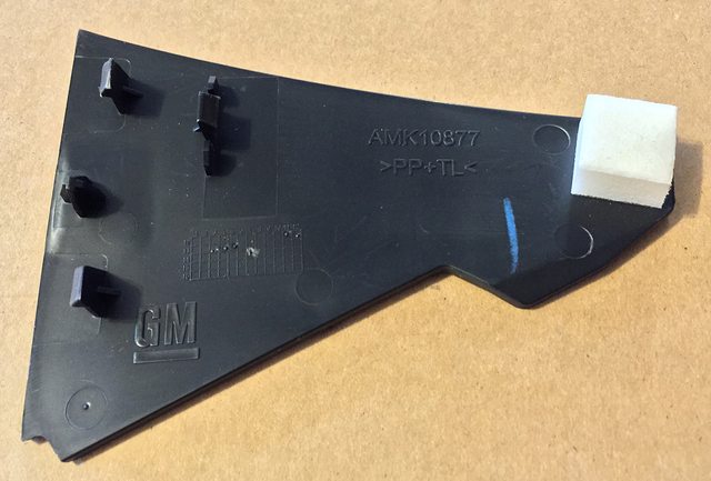
If you are able to find out, can you add the part number for the trim piece drilled for the switch? I will eventually do this and I always like buying replacement OEM parts for the ones I modify.
If you are able to find out, can you add the part number for the trim piece drilled for the switch? I will eventually do this and I always like buying replacement OEM parts for the ones I modify.
Last edited by xp800; 03-31-2015 at 10:04 PM.
03-31-2015, 10:21 PM
#35
Safety Car


Looking / sounding good so far.
I hate crimp connectors, though, so I'll either solder them or use Posi-Locks where butt connectors are needed. Posi-Locks inside the fuse box will also make it really easy to disconnect everything in the fuse box and set back to stock before a trip to the dealer.
Thanks. Look forward to seeing the rest.
03-31-2015, 10:24 PM
#36
Tech Contributor
Thread Starter
Member Since: Jan 2006
Location: Saint Louis MO
Posts: 4,761
Likes: 0
Received 218 Likes
on
110 Posts
St. Jude Donor '14-'15
Looking / sounding good so far.
I hate crimp connectors, though, so I'll either solder them or use Posi-Locks where butt connectors are needed. Posi-Locks inside the fuse box will also make it really easy to disconnect everything in the fuse box and set back to stock before a trip to the dealer.
Thanks. Look forward to seeing the rest.
I hate crimp connectors, though, so I'll either solder them or use Posi-Locks where butt connectors are needed. Posi-Locks inside the fuse box will also make it really easy to disconnect everything in the fuse box and set back to stock before a trip to the dealer.
Thanks. Look forward to seeing the rest.
03-31-2015, 10:51 PM
#38
Tech Contributor
Thread Starter
Member Since: Jan 2006
Location: Saint Louis MO
Posts: 4,761
Likes: 0
Received 218 Likes
on
110 Posts
St. Jude Donor '14-'15
 03-31-2015, 10:54 PM
#39
Tech Contributor
Thread Starter
Member Since: Jan 2006
Location: Saint Louis MO
Posts: 4,761
Likes: 0
Received 218 Likes
on
110 Posts
St. Jude Donor '14-'15
I'm not sure if the non-NPP cars have Fuse 41/42 actually leading anywhere, assuming it has a pinned slot in the first place.
I tried to figure that one out a while ago, but it will come down to a PWM converter and a switched relay to bypass the CCM - pretty positive of that.
03-31-2015, 11:04 PM
#40
I'm Batman..
Pro Mechanic

Member Since: Apr 2014
Location: Lehigh Acres FL
Posts: 6,130
Received 908 Likes
on
561 Posts
Tech Contributor

This would only be for factory-NPP cars. If the NPP conversions end up getting figured out with regard to the PWM and CCM, then you could do something similar.
I'm not sure if the non-NPP cars have Fuse 41/42 actually leading anywhere, assuming it has a pinned slot in the first place.
I tried to figure that one out a while ago, but it will come down to a PWM converter and a switched relay to bypass the CCM - pretty positive of that.
I'm not sure if the non-NPP cars have Fuse 41/42 actually leading anywhere, assuming it has a pinned slot in the first place.
I tried to figure that one out a while ago, but it will come down to a PWM converter and a switched relay to bypass the CCM - pretty positive of that.
 I was hoping that you had that figured out too as part of your DIY. oh wells..