
DIY: Add NPP Switch - True Manual On/Off Valve Control
 03-29-2015, 06:44 PM
#1
Tech Contributor
Thread Starter
Member Since: Jan 2006
Location: Saint Louis MO
Posts: 4,761
Likes: 0
Received 219 Likes
on
110 Posts
St. Jude Donor '14-'15
As we are dealing with voltage, and additional circuit control, I have to put the normal liability clause here.
Neither myself, nor any member of CorvetteForum.com / IB, shall be held liable for any damage or other issue resulting from improper use of these instructions, or from any defect or deficiency in said instructions. No warranty is expressed or implied on the products shown in this thread. It is the responsibility of the reader to take appropriate safety precautions when following any or all parts of these illustrations. No rights are reserved on any materials posted in this thread, and all derivations or additional postings are property of the individual posters/owners.
This has been a long time coming... I had this project all done back last May, but just put it on the back burner. Then the car went to go get built, etc. I'm sorry I've not gotten this out there sooner, but I do hope those of you who have PM'ed me about this are happy with the results!
In yet another attempt to be different (some call it innovative, I call it crazy), I went through several wireless remote relays trying to find something that satisfied my requirements. Sadly, only one out of four was even halfway reliable (but slow to respond), and I wanted something that would work 100% of the time, and immediately. Few of you know how loud these cars can get once they're stroked and straight-through. Even clutched in at 1000rpm makes the ole' butthole pucker passing by a highway patrol car.
Let me emphasize that this is not nearly as hard as it seems - it takes a little work, but what worthwhile mods don't on our C7s? Depending on your skills with wiring, and dis-assembly, this could take you two hours, or two days (let's hope not). Go at your own pace - since you're tapping into the NPP circuit (and essentially moving control of Fuse 41/42 into the cabin), you'll certainly want to make sure you're not rushing it.
Again, though, nothing is overly difficult. I've removed the soldering requirements from the fuse box mod, and gone with an Add-A-Fuse approach now that they are available. I know a few of you will say "But can't we just shove the two wires into the sockets and mash them down with a blown fuse?"... Well, yes, you can, but I'm not going to endorse it.
Soldering has come and gone several times in this DIY... The switch mounting location is interfered with when the entertainment screen moves down. This prohibits the use of disconnects, and requires the switch leads to be trimmed and soldered. While this is a far better connection, if you would prefer to keep this completely solderless, we can look into an additional switch location.
Let me know what you guys think - this may eventually go into the How-To section, but for now, I'm going to keep it as a DIY to see how everyone feels about it. I feel that it's a great, cheap, simple mod to force the NPP valves into doing exactly what we want (without any risk or damage to the system or subsystems [CCM, etc.]), but there's still an enormous amount of confusion and misinformation out there about how NPP actually works. I don't want to get into that here, so let's please keep this focused on the mod, itself. xp800 has done a great job keeping up with all of those questions in his thread, as it seemed like every time I would post, three people would try to contradict what the facts were. I had to finally give up, which usually isn't my style.
Anyway, there is no question about how this one works. Two modes: 1) Switch on, power flowing, valves closed. 2) Switch off, power not flowing, valves open. That's all there is to it. It's the same as if you got out of the car to pull Fuse 41/42 or put it back in - though this is more practical at 60mph!
This does not, will not, and can not affect the AFM valves. That's a problem you either fix another way or live with it.
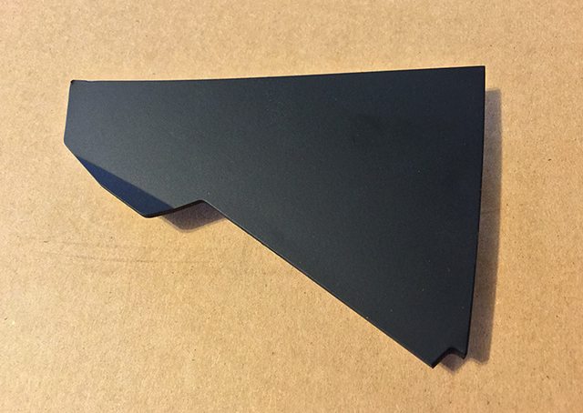
Additional positives to this mod worth mentioning are that the console panel I've chosen to use is relatively inexpensive (~$50), and the location is near-perfect. The choice of switch can be left up to you - if you want a lighted 12V switch, great. Normal no-frills switch more to your liking? Go for it! Any SPST (no, not SPDT, not DPDT, nothing more than a simple SPST) rated at 12V 20A or higher will work. Routing the wires through the firewall isn't awful - it just takes a bit of effort if you've not done it before. Best part of this is that it is 100% reversible - returning to stock simply requires removing the wires, and replacing the factory fuse/panel.
I will create this thread as I've been doing with my DIYs for a while now by first posting this introduction, and then using the next few posts to give a walkthrough with several pictures, etc. A parts list is provided in the next post, and everything can be purchased and installed in the same day - with additional options listed to order from eBay or Amazon if an AutoZone is out of stock on some items.
Special thanks to xp800 for the original thread, and to grandpawmoses for the input leading to the final revision, and for the pictures of the new routing option, which is far easier than the original requiring the fender liner removal, etc.
Neither myself, nor any member of CorvetteForum.com / IB, shall be held liable for any damage or other issue resulting from improper use of these instructions, or from any defect or deficiency in said instructions. No warranty is expressed or implied on the products shown in this thread. It is the responsibility of the reader to take appropriate safety precautions when following any or all parts of these illustrations. No rights are reserved on any materials posted in this thread, and all derivations or additional postings are property of the individual posters/owners.
This has been a long time coming... I had this project all done back last May, but just put it on the back burner. Then the car went to go get built, etc. I'm sorry I've not gotten this out there sooner, but I do hope those of you who have PM'ed me about this are happy with the results!
In yet another attempt to be different (some call it innovative, I call it crazy), I went through several wireless remote relays trying to find something that satisfied my requirements. Sadly, only one out of four was even halfway reliable (but slow to respond), and I wanted something that would work 100% of the time, and immediately. Few of you know how loud these cars can get once they're stroked and straight-through. Even clutched in at 1000rpm makes the ole' butthole pucker passing by a highway patrol car.
Let me emphasize that this is not nearly as hard as it seems - it takes a little work, but what worthwhile mods don't on our C7s? Depending on your skills with wiring, and dis-assembly, this could take you two hours, or two days (let's hope not). Go at your own pace - since you're tapping into the NPP circuit (and essentially moving control of Fuse 41/42 into the cabin), you'll certainly want to make sure you're not rushing it.
Again, though, nothing is overly difficult. I've removed the soldering requirements from the fuse box mod, and gone with an Add-A-Fuse approach now that they are available. I know a few of you will say "But can't we just shove the two wires into the sockets and mash them down with a blown fuse?"... Well, yes, you can, but I'm not going to endorse it.
Soldering has come and gone several times in this DIY... The switch mounting location is interfered with when the entertainment screen moves down. This prohibits the use of disconnects, and requires the switch leads to be trimmed and soldered. While this is a far better connection, if you would prefer to keep this completely solderless, we can look into an additional switch location.
Let me know what you guys think - this may eventually go into the How-To section, but for now, I'm going to keep it as a DIY to see how everyone feels about it. I feel that it's a great, cheap, simple mod to force the NPP valves into doing exactly what we want (without any risk or damage to the system or subsystems [CCM, etc.]), but there's still an enormous amount of confusion and misinformation out there about how NPP actually works. I don't want to get into that here, so let's please keep this focused on the mod, itself. xp800 has done a great job keeping up with all of those questions in his thread, as it seemed like every time I would post, three people would try to contradict what the facts were. I had to finally give up, which usually isn't my style.
Anyway, there is no question about how this one works. Two modes: 1) Switch on, power flowing, valves closed. 2) Switch off, power not flowing, valves open. That's all there is to it. It's the same as if you got out of the car to pull Fuse 41/42 or put it back in - though this is more practical at 60mph!
This does not, will not, and can not affect the AFM valves. That's a problem you either fix another way or live with it.
Additional positives to this mod worth mentioning are that the console panel I've chosen to use is relatively inexpensive (~$50), and the location is near-perfect. The choice of switch can be left up to you - if you want a lighted 12V switch, great. Normal no-frills switch more to your liking? Go for it! Any SPST (no, not SPDT, not DPDT, nothing more than a simple SPST) rated at 12V 20A or higher will work. Routing the wires through the firewall isn't awful - it just takes a bit of effort if you've not done it before. Best part of this is that it is 100% reversible - returning to stock simply requires removing the wires, and replacing the factory fuse/panel.
I will create this thread as I've been doing with my DIYs for a while now by first posting this introduction, and then using the next few posts to give a walkthrough with several pictures, etc. A parts list is provided in the next post, and everything can be purchased and installed in the same day - with additional options listed to order from eBay or Amazon if an AutoZone is out of stock on some items.
Special thanks to xp800 for the original thread, and to grandpawmoses for the input leading to the final revision, and for the pictures of the new routing option, which is far easier than the original requiring the fender liner removal, etc.
Last edited by Theta; 06-16-2015 at 10:28 PM.

The following 2 users liked this post by Theta:
itspeat (05-13-2017),
OctagonMan (03-07-2019)
03-29-2015, 06:45 PM
#2
Tech Contributor
Thread Starter
Member Since: Jan 2006
Location: Saint Louis MO
Posts: 4,761
Likes: 0
Received 219 Likes
on
110 Posts
St. Jude Donor '14-'15
Tools Needed:
Parts List:
AutoZone:
Pictures of items (in order):
- T15 Torx Bit or Driver (For loosening A-pillar cover)
- 1" Spade Bit/Hole Saw/Drill Bit (For drilling switch hole in panel)
- Heat Gun or >800W Hairdryer (For shrinking heat shrink tube)
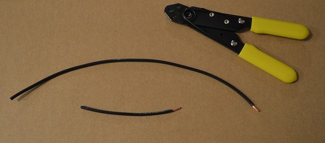
- Wire Cutters/Strippers (For Cutting/Stripping Ends of Primary wire/Fuse Wire)
- Wire Crimpers - Buy a good one if you don't have a decent one! (For Crimping Ends of Primary wire/Fuse Wire to connectors)
- Scissors (To cut heatshrink/tubing to size - not to cut wire with)
Parts List:
AutoZone:
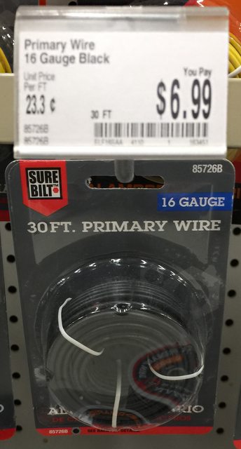
- 1 x 30ft 16ga Black Electrical Wire/Primary Wire - Part Number: 85726B
or 1 x 20ft 14ga Black Electrical Wire/Primary Wire - Part Number: 85718B
(Fuse/Wiring Aisle) - $6.99
Color options to differentiate the 12v from the load wire:
16ga: Red=85724R, White=85727W, Green=85731G, Blue=85728B, Yellow=85730Y
14ga: Red=85716R, White=85719W, Green=85723G, Blue=85720B, Yellow=85722Y
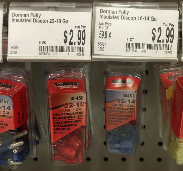
- 1 x Dorman/Fully Insulated Quick-Disconnect Terminal Set (5 pairs) - Part Number: 85460
(Fuse/Wiring Aisle) - $2.99
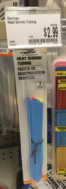
- 1 x Dorman/Heat Shrink Tubing - Part Number: 85686
(Fuse/Wiring Aisle) - $2.99
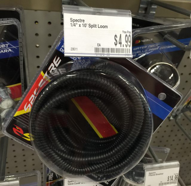
- 1 x 1/4" Plastic Split Loom Tubing - Part Number: 29511
(Specialty Aisle) - $4.99
Alternate Part @ Amazon (Prime Eligible):
Alt. Part - Techflex @ Amazon (Prime Eligible):
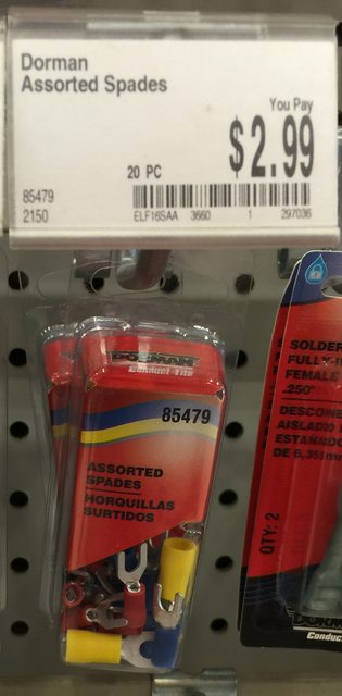
- 1 x Dorman/Mix Spade Connector - Part Number: 85479
(Fuse/Wiring Aisle) - $2.99
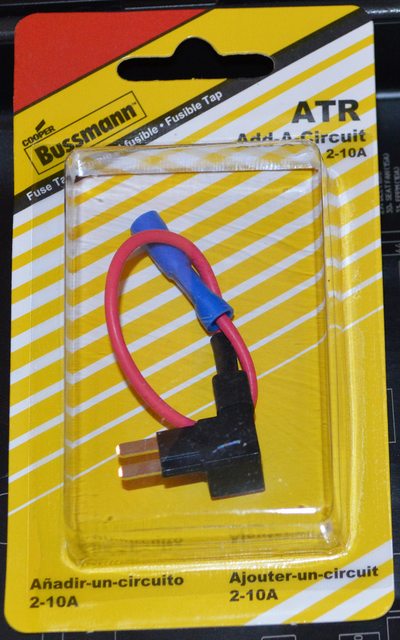
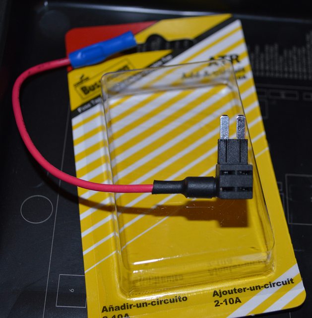
- 1 x Bussmann ATR Micro2 Add-A-Circuit - Part Number: BP-HHTR-RP
(Fuse/Wiring Aisle) - $6.99 - Does not appear online.
Alternate Part @ Amazon (Prime Eligible):
Alternate Part @ eBay (example): http://www.ebay.com/itm/NEW-ADD-A-CI...G/221517824774
- Choice of Switch
- [*]
Pictures of items (in order):
Last edited by Theta; 04-08-2015 at 05:13 PM. Reason: Added content.
03-29-2015, 06:46 PM
#3
Tech Contributor
Thread Starter
Member Since: Jan 2006
Location: Saint Louis MO
Posts: 4,761
Likes: 0
Received 219 Likes
on
110 Posts
St. Jude Donor '14-'15
Soldered option removed due to complexity. Those wishing to solder joints rather than crimp can certainly do so!
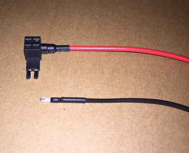
Begin by cutting two lengths of 16AWG primary wire, one 7-inches in length, the other 3-inches in length. Strip one end of both wires - 1/4" exposed wire is perfect. Set these wires aside.
Remove the Add-A-Circuit from the packaging. Regardless of where you purchased this, they will all look and work identically. The Bussmann rating of 2-10A is incorrect. The fixture is rated from 1A to 20A with a 16ga 5" lead. There is a wiring guide on page 2 that goes more in-depth with this.
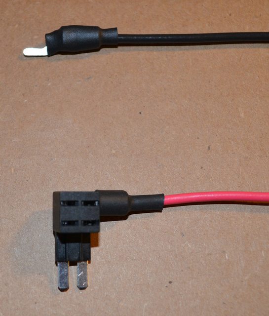
Next, open the box of assorted spades, and remove one blue spade. Cut the right 'fork' off of the spade, making sure there are no sharp edges remaining. A small metal file works well for this.
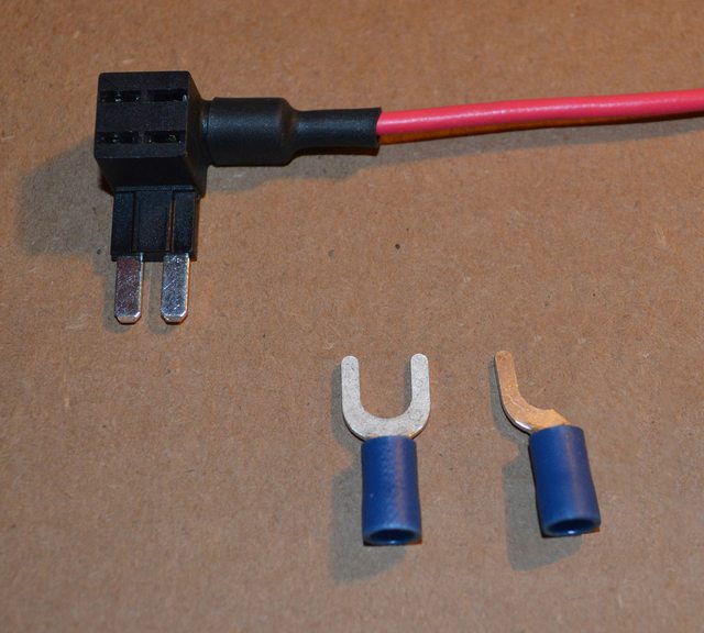
Take the 7" wire set aside, and insert one of the stripped ends into the cut spade crimp area. Crimp the wire securely using a quality wire crimper. These crimps must be done correctly as to not cause shorts in the system, which can lead to shocks, fires, etc.
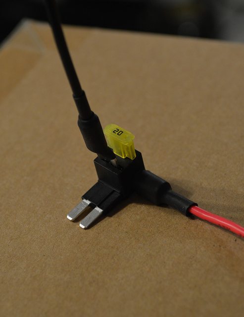
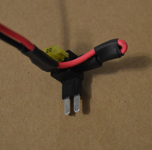
Take a length of 1/4" heat shrink tube, and cut a small piece off - approximately 1-inch long. Slide the shrink tube over the spade, making sure to cover the middle of the fork, as shown below. Using a heat gun on low, or hair dryer on high, heat the shrink tube until it is fully shrunk. Your result should look like this:
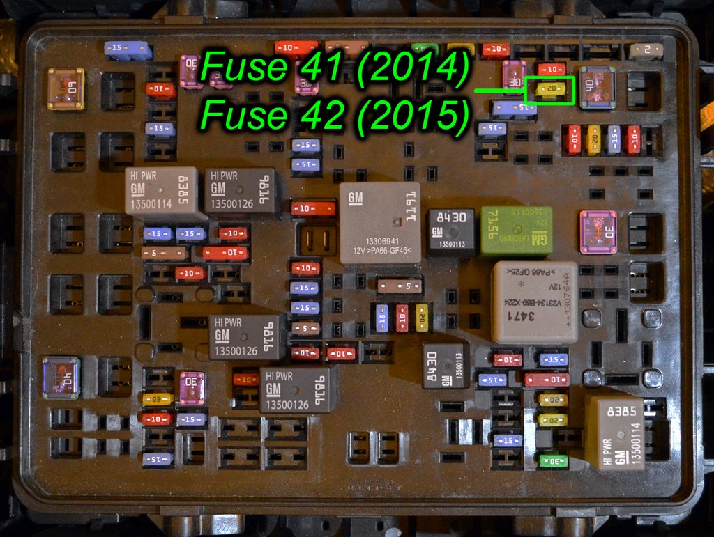
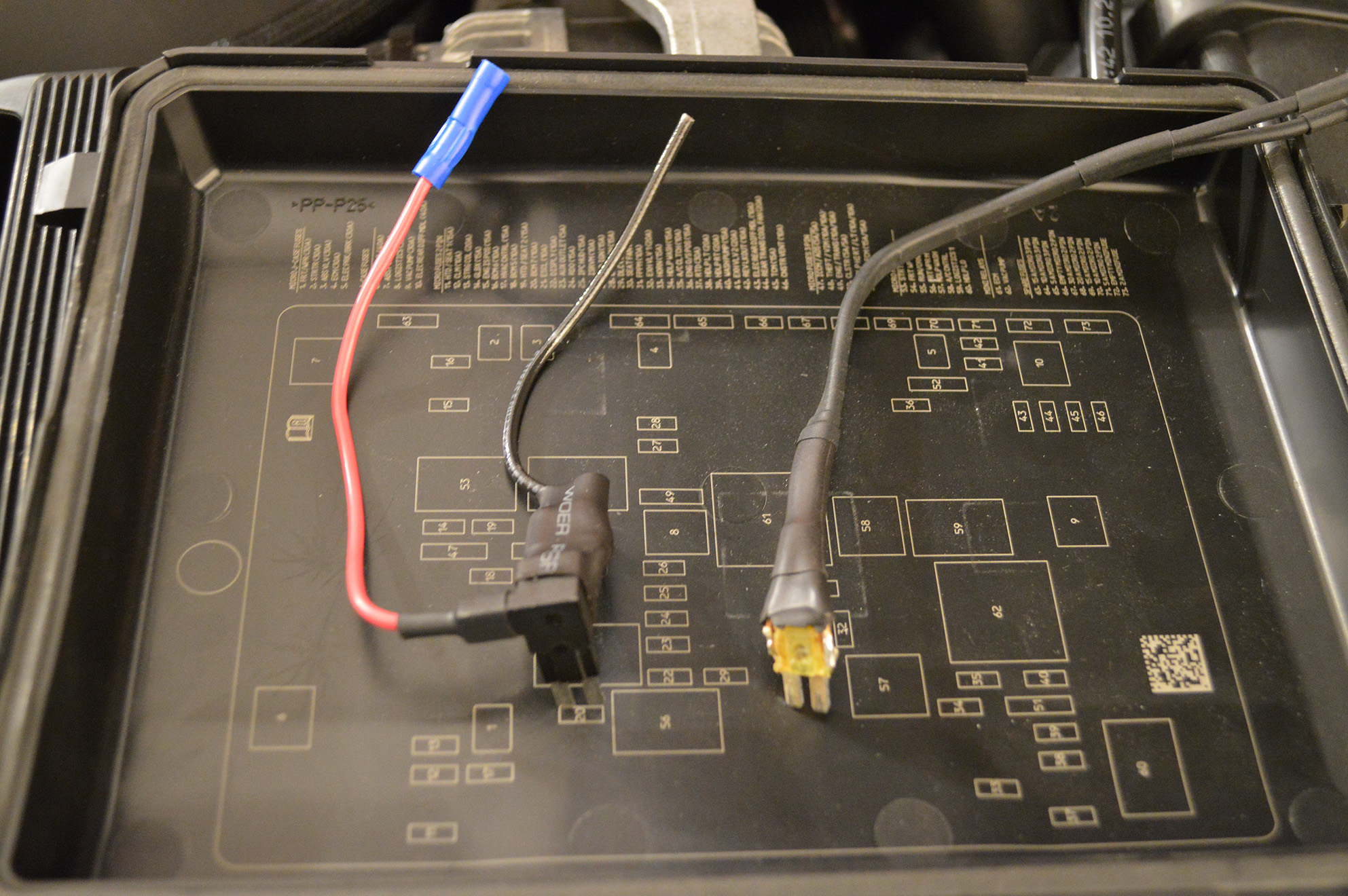
Remove the 20A Micro2 fuse from the front fuse box, position 41 (2014 only) or position 42 (2015 only) - same physical location, same 20A fuse.
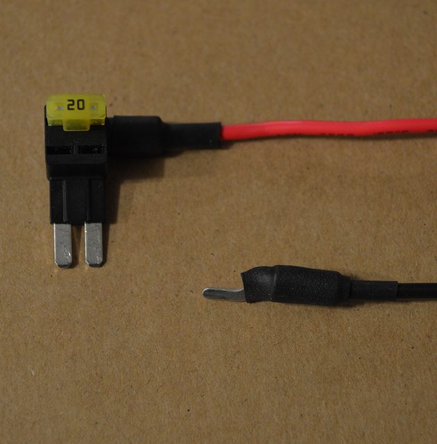
Insert the 20A Micro2 fuse into the top fuse slot of the Add-a-Circuit.
Insert the spade-terminated wire into the lower right slot as shown:
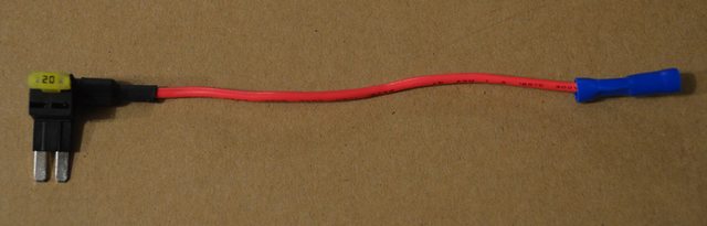
Insert the 3" wire set aside into the blue crimp connector coming from the Add-a-Circuit. Crimp this small wire using the pre-crimped blue connector.
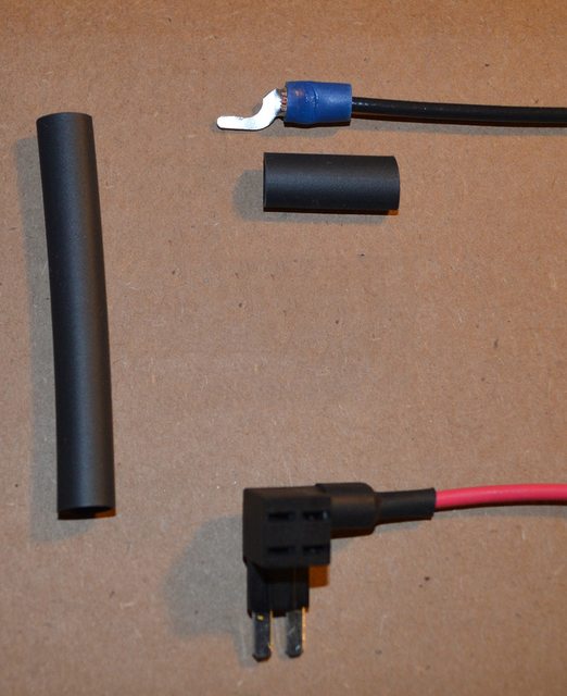
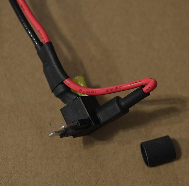
I took this opportunity to give the spade a bit of support by using a few pieces of 1/4" heat shrink to secure the wires to each other.
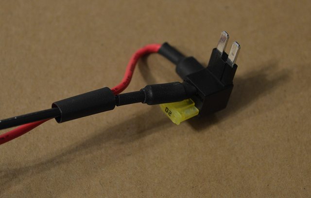
To make sure the red wire didn't pull on the spade, I also added a piece of heat shrink to the cable bend as shown:
For those that prefer to solder connections, solder the blade of a micro fuse (solder to the upper shoulder of the single fuse blade) to the wire and use shrink tube. This method does not require any additional bracing with shrink tube, as the fuse leg is held very tightly in the fuse slot.
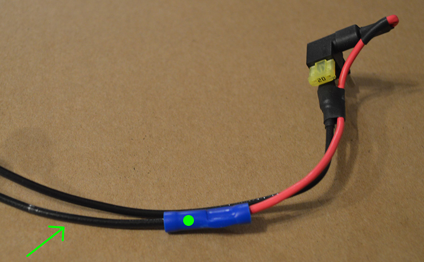
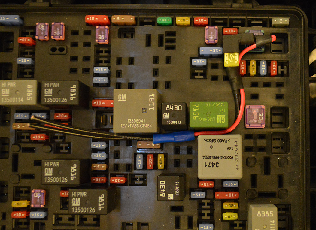
Test fit the assembly in the fuse box. Route the cabling similar to this example, and even out the length of the two wires as needed.
Once you have completed cutting the length of the wires, strip the ends of both wires leaving 1/4" exposed wire.
Note: Before crimping, you may want to place a length of 1/4" shrink tube over the blue butt crimp, and slide an inch of 1/4" shrink tube on each wire to seal the disconnect to the wire after being crimped next. This is not shown in the following pictures.
Crimp an insulated disconnect on each of the two wires. The red lead from the Add-a-Circuit is 12v hot, so if you would like to crimp a specific gender to signify this, feel free to do so. For this example, I have used male spades on both wires.
Note that it is important to know which wire is hot when running a lighted switch. If you would prefer to run red primary wire for this lead, see the parts list above for the red wire part number. Additionally, feel free to run a 3" red wire from the blue crimp connector, then to a spade gender of your choosing.
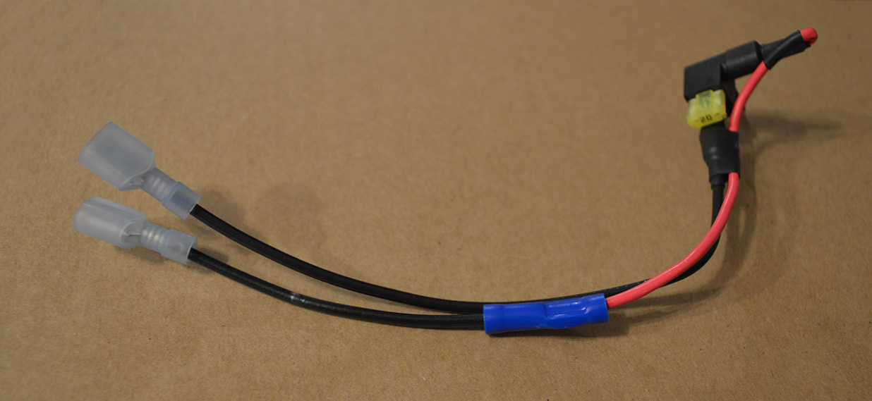
This completes the fuse box portion of the wiring. Now, we just need to get the cabin wiring to the fusebox, which is more tedious than it is difficult. See next post.
Begin by cutting two lengths of 16AWG primary wire, one 7-inches in length, the other 3-inches in length. Strip one end of both wires - 1/4" exposed wire is perfect. Set these wires aside.
Remove the Add-A-Circuit from the packaging. Regardless of where you purchased this, they will all look and work identically. The Bussmann rating of 2-10A is incorrect. The fixture is rated from 1A to 20A with a 16ga 5" lead. There is a wiring guide on page 2 that goes more in-depth with this.
Next, open the box of assorted spades, and remove one blue spade. Cut the right 'fork' off of the spade, making sure there are no sharp edges remaining. A small metal file works well for this.
Take the 7" wire set aside, and insert one of the stripped ends into the cut spade crimp area. Crimp the wire securely using a quality wire crimper. These crimps must be done correctly as to not cause shorts in the system, which can lead to shocks, fires, etc.
Take a length of 1/4" heat shrink tube, and cut a small piece off - approximately 1-inch long. Slide the shrink tube over the spade, making sure to cover the middle of the fork, as shown below. Using a heat gun on low, or hair dryer on high, heat the shrink tube until it is fully shrunk. Your result should look like this:
Remove the 20A Micro2 fuse from the front fuse box, position 41 (2014 only) or position 42 (2015 only) - same physical location, same 20A fuse.
Insert the 20A Micro2 fuse into the top fuse slot of the Add-a-Circuit.
Insert the spade-terminated wire into the lower right slot as shown:
Insert the 3" wire set aside into the blue crimp connector coming from the Add-a-Circuit. Crimp this small wire using the pre-crimped blue connector.
I took this opportunity to give the spade a bit of support by using a few pieces of 1/4" heat shrink to secure the wires to each other.
To make sure the red wire didn't pull on the spade, I also added a piece of heat shrink to the cable bend as shown:
For those that prefer to solder connections, solder the blade of a micro fuse (solder to the upper shoulder of the single fuse blade) to the wire and use shrink tube. This method does not require any additional bracing with shrink tube, as the fuse leg is held very tightly in the fuse slot.
Test fit the assembly in the fuse box. Route the cabling similar to this example, and even out the length of the two wires as needed.
Once you have completed cutting the length of the wires, strip the ends of both wires leaving 1/4" exposed wire.
Note: Before crimping, you may want to place a length of 1/4" shrink tube over the blue butt crimp, and slide an inch of 1/4" shrink tube on each wire to seal the disconnect to the wire after being crimped next. This is not shown in the following pictures.
Crimp an insulated disconnect on each of the two wires. The red lead from the Add-a-Circuit is 12v hot, so if you would like to crimp a specific gender to signify this, feel free to do so. For this example, I have used male spades on both wires.
Note that it is important to know which wire is hot when running a lighted switch. If you would prefer to run red primary wire for this lead, see the parts list above for the red wire part number. Additionally, feel free to run a 3" red wire from the blue crimp connector, then to a spade gender of your choosing.
This completes the fuse box portion of the wiring. Now, we just need to get the cabin wiring to the fusebox, which is more tedious than it is difficult. See next post.
Last edited by Theta; 04-11-2015 at 03:30 AM.
The following users liked this post:
solotronics (01-01-2019)
03-29-2015, 06:46 PM
#4
Tech Contributor
Thread Starter
Member Since: Jan 2006
Location: Saint Louis MO
Posts: 4,761
Likes: 0
Received 219 Likes
on
110 Posts
St. Jude Donor '14-'15
Installation of switch and wiring to fusebox...
In Progress...
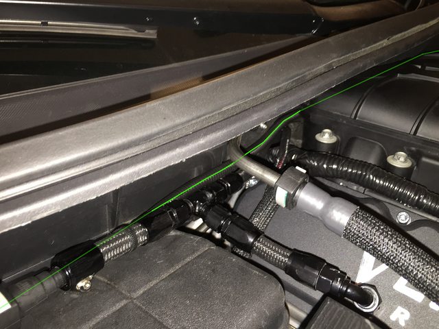
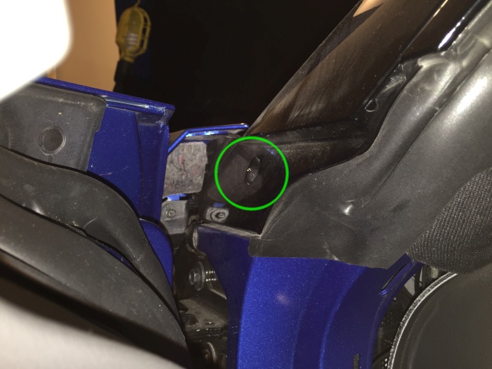
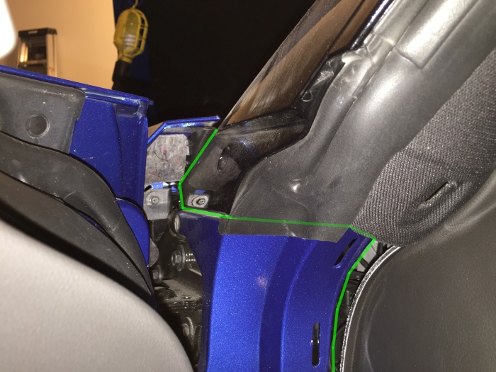
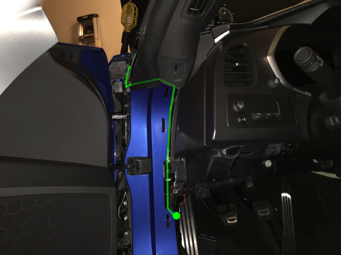
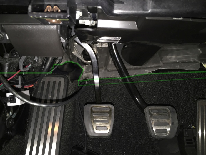
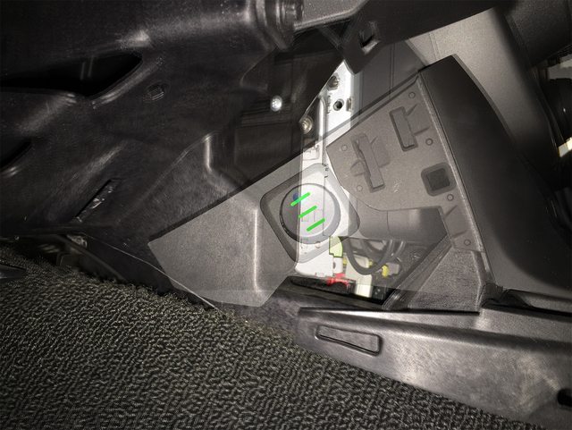
There will be two examples of mounting shown in this next section, and routing is slightly changed for each one. For the sake of simplicity, we will use grandpawmoses' routing method, which I've begun to refer to as the 'around the post' method, as it does not require the use of a jack, removal of the front wheel, fender liner, etc. For those of you familiar with running wires through the 'clutch grommet', feel free to use that routing method. Many of us have used this for Alky meth installs, gauges, etc.
If you plan to locate the switch on the driver's door sill / kick panel, begin by cutting two 8-foot lengths of wire - Note: If you used the AZ 16ga, you will have plenty left over - if you used the AZ 14ga, you may need another spool.
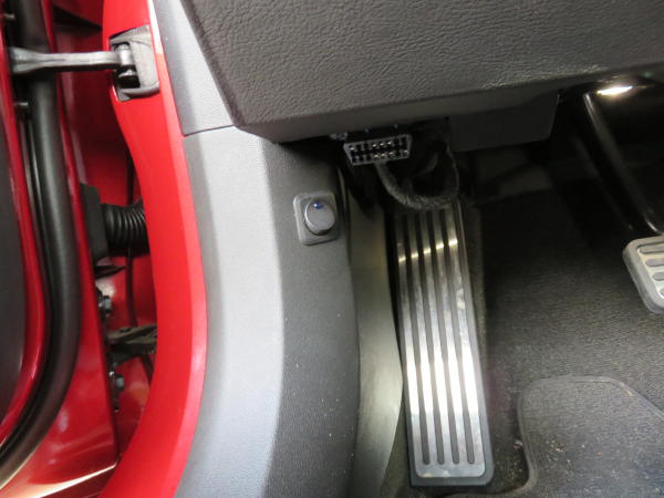
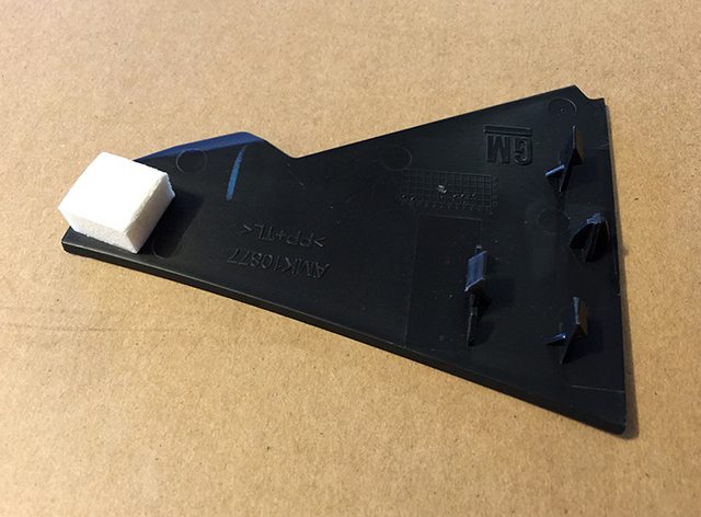
If you plan to locate the switch on the small panel on the side of the console (which requires the cutting of & soldering to the switch terminals), begin by cutting two 10-foot lengths of wire - Note: Same caution as above. Please note that this area is very tight due to the screen coming down - deep switches will interfere with the mechanism. Only by soldering flat to the rear of the switch can you hope to fit the AZ switch in there. Mouser stocks Cherry and a few other round switches that are more shallow and would work better for this.
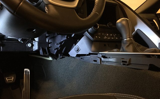
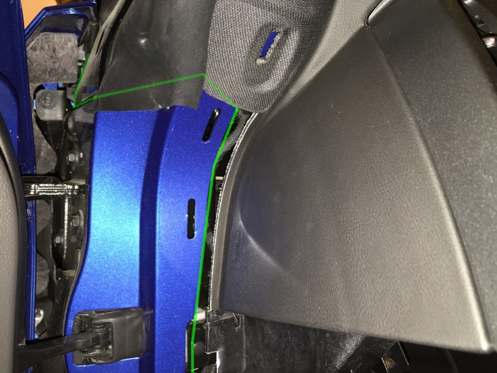
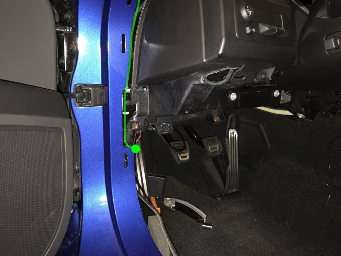
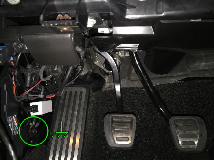
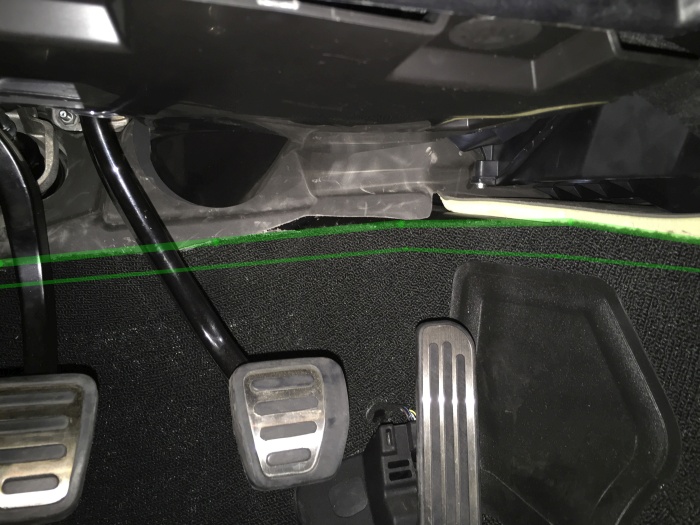
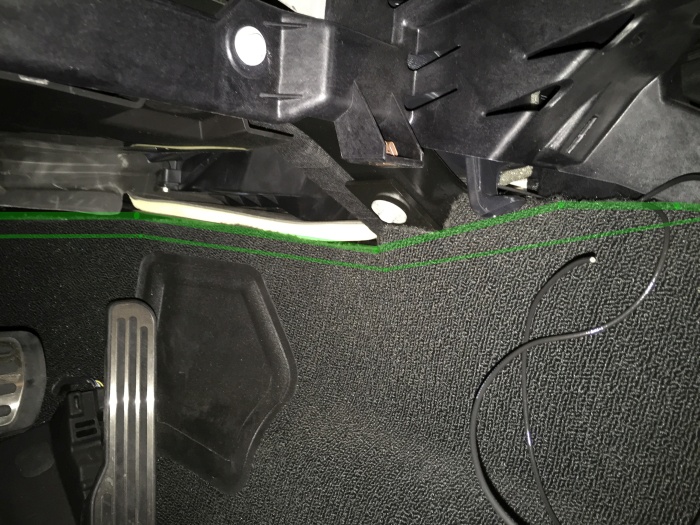
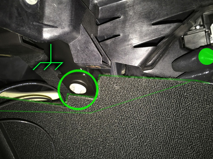
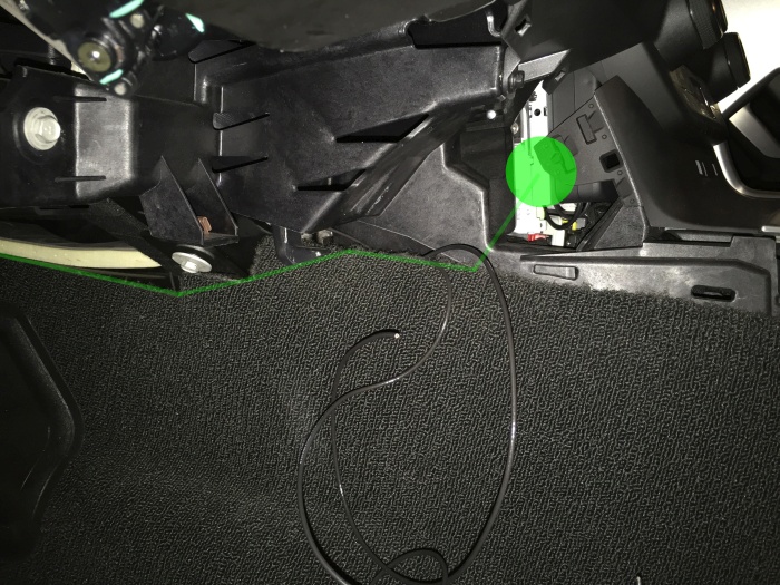
Starting at the fuse box, route the wiring as shown (or in a similar manner), leaving 6 inches of each wire to spare for adjustment, etc. Note that you do not need to use the split loom tubing until your wiring is final, though I chose to use it from the beginning just to make things easier. You will want to make sure and leave yourself plenty of extra tubing when you cut, for adjustment, etc.
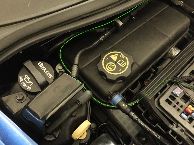
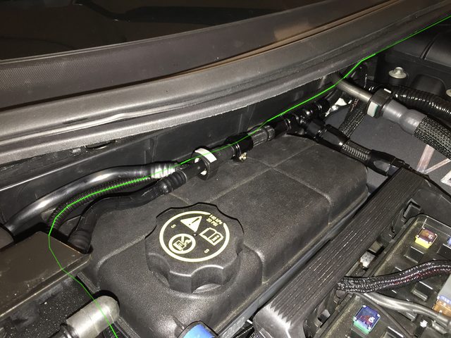
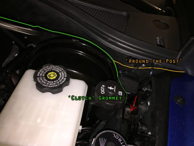
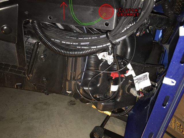
The next picture shows the routing I used for the clutch grommet method, and I'll leave these here for anyone else who would like to use that route. Otherwise, we'll move on to the aptly-named 'around the post' method.
I will add / edit / update text on these ASAP.
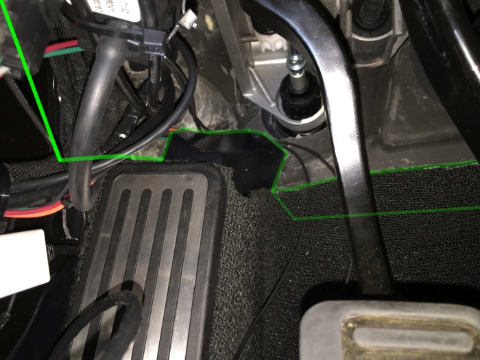
In Progress...
There will be two examples of mounting shown in this next section, and routing is slightly changed for each one. For the sake of simplicity, we will use grandpawmoses' routing method, which I've begun to refer to as the 'around the post' method, as it does not require the use of a jack, removal of the front wheel, fender liner, etc. For those of you familiar with running wires through the 'clutch grommet', feel free to use that routing method. Many of us have used this for Alky meth installs, gauges, etc.
If you plan to locate the switch on the driver's door sill / kick panel, begin by cutting two 8-foot lengths of wire - Note: If you used the AZ 16ga, you will have plenty left over - if you used the AZ 14ga, you may need another spool.
If you plan to locate the switch on the small panel on the side of the console (which requires the cutting of & soldering to the switch terminals), begin by cutting two 10-foot lengths of wire - Note: Same caution as above. Please note that this area is very tight due to the screen coming down - deep switches will interfere with the mechanism. Only by soldering flat to the rear of the switch can you hope to fit the AZ switch in there. Mouser stocks Cherry and a few other round switches that are more shallow and would work better for this.
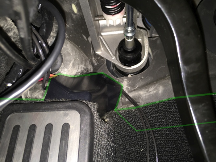
Starting at the fuse box, route the wiring as shown (or in a similar manner), leaving 6 inches of each wire to spare for adjustment, etc. Note that you do not need to use the split loom tubing until your wiring is final, though I chose to use it from the beginning just to make things easier. You will want to make sure and leave yourself plenty of extra tubing when you cut, for adjustment, etc.
The next picture shows the routing I used for the clutch grommet method, and I'll leave these here for anyone else who would like to use that route. Otherwise, we'll move on to the aptly-named 'around the post' method.
I will add / edit / update text on these ASAP.
Last edited by Theta; 06-16-2015 at 10:31 PM.
The following users liked this post:
solotronics (01-01-2019)
03-29-2015, 10:35 PM
#5
Tech Contributor
Thread Starter
Member Since: Jan 2006
Location: Saint Louis MO
Posts: 4,761
Likes: 0
Received 219 Likes
on
110 Posts
St. Jude Donor '14-'15
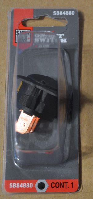
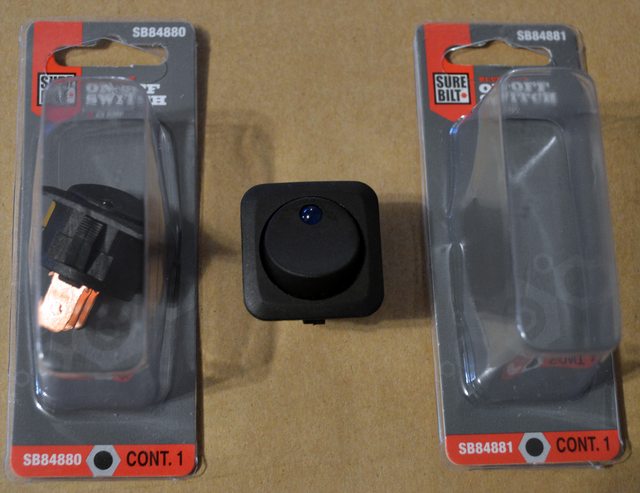
As mentioned in the parts post, there are two good options for switches available at AutoZone. Note that you can use any other type there or elsewhere, so long as it's an SPST. It does not need to be lighted, but this walkthrough will include the extra wiring for the LED.
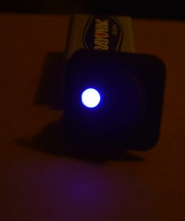
Here's a picture of the switch - they're identical except for the LED:
So, next up, we shift to the brightness of the LEDs. Suffice to say that both are stupidly bright (even at only 9v), and would become incredibly annoying at night. Here's an idea of how bright we're talking (the first photo is a control shot with the lens settings and normal lighting):
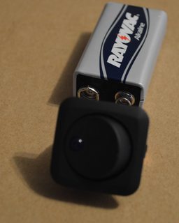
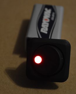
So, yes - the blue is stupidly bright, as it has a fairly high mA consumption rating. Also, these tests are at just 9v. Let's step this up to a lab inverter @ 13v nominal (pictures are intentionally distorted in some cases):
This was taken from 10 feet away - note the bright reflection off the underbelly pan from the C7!

Let's look at both of them side-by-side in normal lighting (same as always):
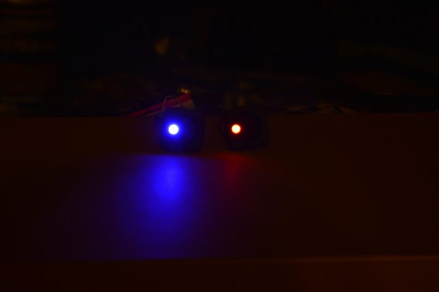
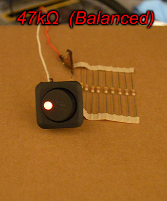
So we're all in agreement here that the blue is stupidly bright. That being said, I want blue - just not that much of it. Time to whip out the resistors!
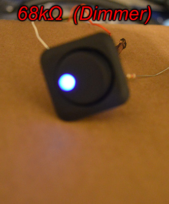
I'll save you a lot of time and just get down to it. Remember that the source on this is being passed on to the load, so putting a resistor on the forward voltage will end very badly. So, use a 1/4W on the ground (which is only used for the LED - I've made sure of this) and that's that.
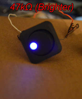
For a sensibly-bright blue glow, use one 68kOhm resistor. For a brighter daytime-oriented blue glow, use one 47kOhm resistor. For a balanced red glow, use one 47kOhm resistor.
And finally, if you don't want an LED on the switch at all, no problem! You can either source another non-LED SPST from Amazon, etc. Or, you can choose to not wire the LED and save a bit of time.
As for the resistors, that's the kind of thing that I get off on a tangent with, and get slowed down. But hey - it's a time savings to the others out there that will (certainly) want to dim these things down!
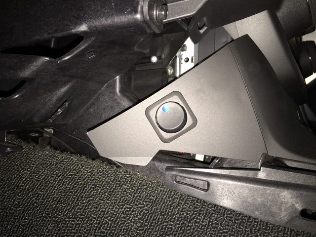
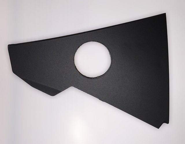
Sneak preview of the finished product:

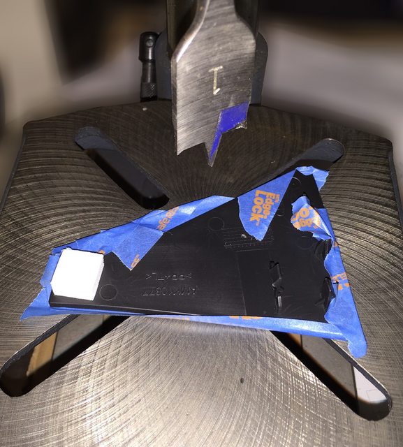
Spade bit is a little messy compared to a quality hole saw/tile saw:
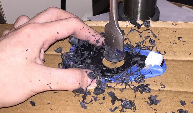
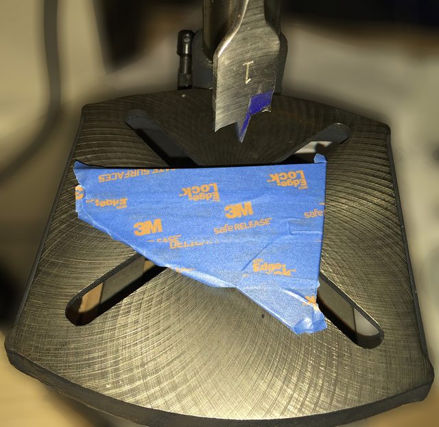
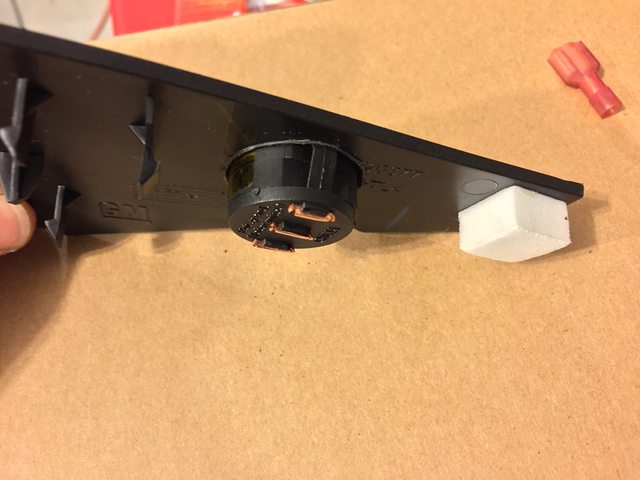
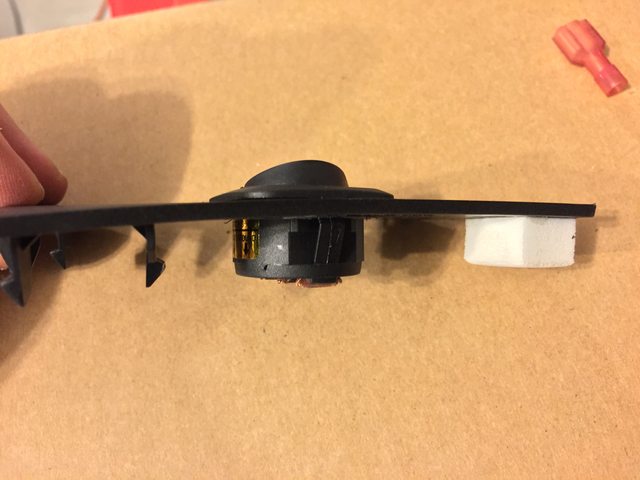
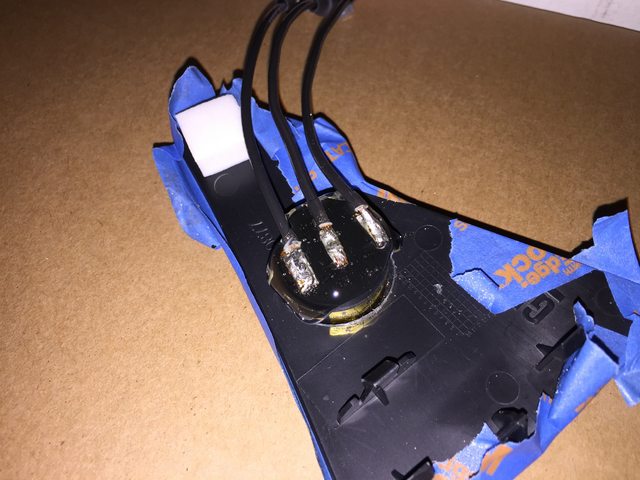
Caution - if installing the switch on the right (small) panel, cutting off and soldering to the switch terminals is required. The entertainment screen moves down causing any connectors to impede the travel. There is just enough room to solder wires at a right angle and protect them with a generous amount of hot glue/liquid electrical tape/etc.
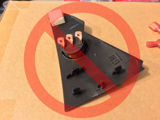
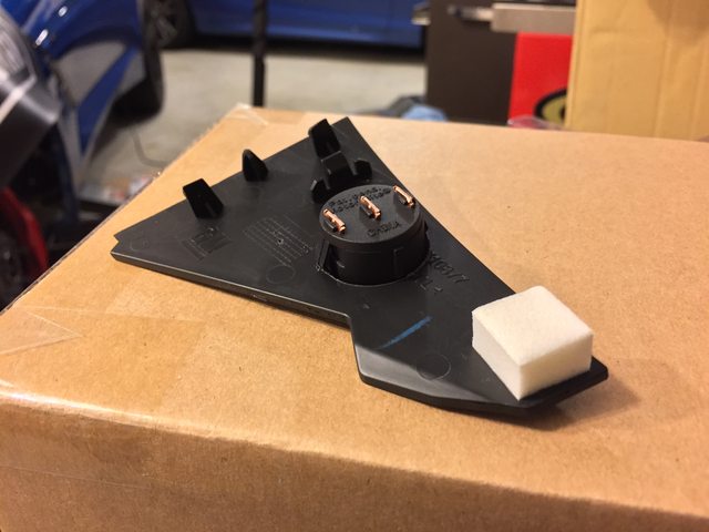
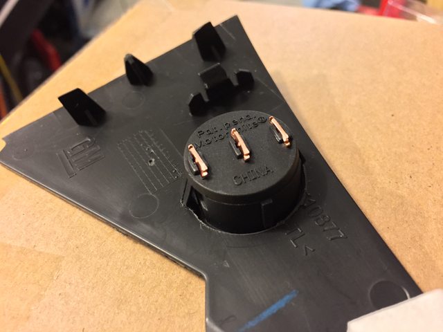
Clip the copper leads to leave only a small amount of material left on the rear of the switch. Be careful soldering to the leads, as if they overheat, you will destroy the switch. However, you also need to be careful to heat the leads enough to prevent getting a cold joint. To tin/join the leads with a micro-tip (and not get a cold joint) I needed to use ~325deg C and low-temp silver bearing solder.
I also recommend using painter's tape on the panel face when soldering. Sure, you can take the switch out, as well, but this gave me more balance for the tabletop. If you use a small clamp, you're all set - just protect the face.
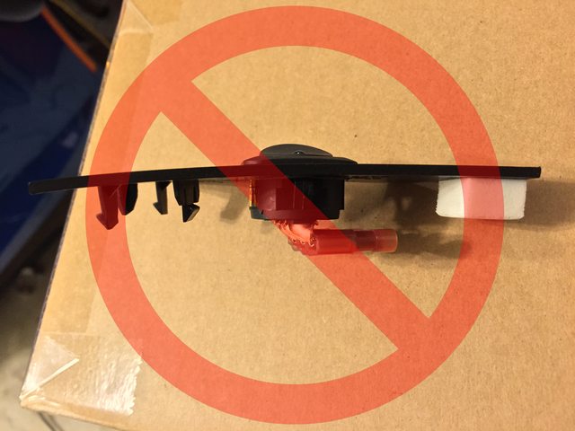
Once you have the wires soldered to the switch, select your choice of color and gender for quick disconnects, crimp, and heat shrink. Here, I'm using three different connectors to keep these straight without having to backtrace the circuit.
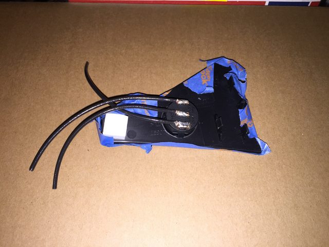
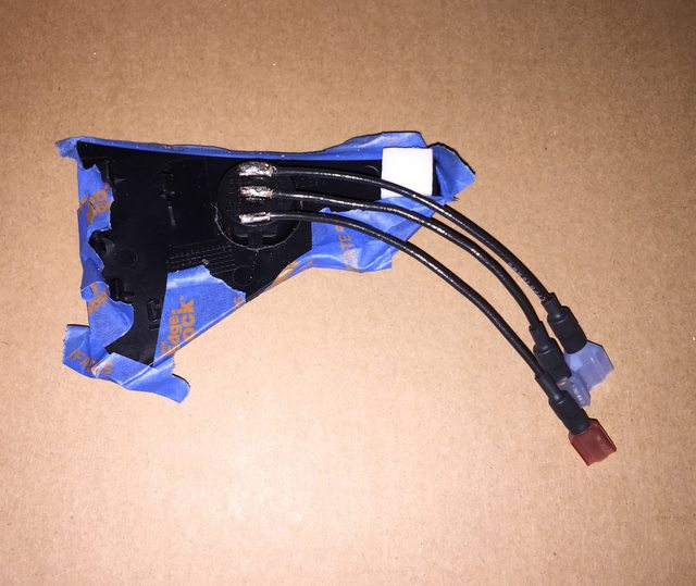
Lastly, and most importantly (as there is a high-amp ground risk), cover the solder joints with an appropriate insulator. I've chosen high-temp hot glue, which turns to a near-epoxy strength insulator. You can also use liquid electrical tape, etc. Be sure to use enough to also give you some passive cable strain relief.
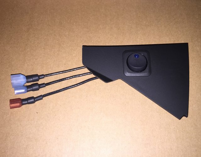
All done! One last test fit with the screen down, and then it's time to plug in the mating cables, and pop the panel back in for good.
Here's a picture of the switch - they're identical except for the LED:
So, next up, we shift to the brightness of the LEDs. Suffice to say that both are stupidly bright (even at only 9v), and would become incredibly annoying at night. Here's an idea of how bright we're talking (the first photo is a control shot with the lens settings and normal lighting):
So, yes - the blue is stupidly bright, as it has a fairly high mA consumption rating. Also, these tests are at just 9v. Let's step this up to a lab inverter @ 13v nominal (pictures are intentionally distorted in some cases):
This was taken from 10 feet away - note the bright reflection off the underbelly pan from the C7!
Let's look at both of them side-by-side in normal lighting (same as always):
So we're all in agreement here that the blue is stupidly bright. That being said, I want blue - just not that much of it.
Time to whip out the resistors!I'll save you a lot of time and just get down to it. Remember that the source on this is being passed on to the load, so putting a resistor on the forward voltage will end very badly. So, use a 1/4W on the ground (which is only used for the LED - I've made sure of this) and that's that.
For a sensibly-bright blue glow, use one 68kOhm resistor. For a brighter daytime-oriented blue glow, use one 47kOhm resistor. For a balanced red glow, use one 47kOhm resistor.
And finally, if you don't want an LED on the switch at all, no problem! You can either source another non-LED SPST from Amazon, etc. Or, you can choose to not wire the LED and save a bit of time.
As for the resistors, that's the kind of thing that I get off on a tangent with, and get slowed down. But hey - it's a time savings to the others out there that will (certainly) want to dim these things down!
Sneak preview of the finished product:
Spade bit is a little messy compared to a quality hole saw/tile saw:
Caution - if installing the switch on the right (small) panel, cutting off and soldering to the switch terminals is required. The entertainment screen moves down causing any connectors to impede the travel. There is just enough room to solder wires at a right angle and protect them with a generous amount of hot glue/liquid electrical tape/etc.
Clip the copper leads to leave only a small amount of material left on the rear of the switch. Be careful soldering to the leads, as if they overheat, you will destroy the switch. However, you also need to be careful to heat the leads enough to prevent getting a cold joint. To tin/join the leads with a micro-tip (and not get a cold joint) I needed to use ~325deg C and low-temp silver bearing solder.
I also recommend using painter's tape on the panel face when soldering. Sure, you can take the switch out, as well, but this gave me more balance for the tabletop. If you use a small clamp, you're all set - just protect the face.
Once you have the wires soldered to the switch, select your choice of color and gender for quick disconnects, crimp, and heat shrink. Here, I'm using three different connectors to keep these straight without having to backtrace the circuit.
Lastly, and most importantly (as there is a high-amp ground risk), cover the solder joints with an appropriate insulator. I've chosen high-temp hot glue, which turns to a near-epoxy strength insulator. You can also use liquid electrical tape, etc. Be sure to use enough to also give you some passive cable strain relief.
All done! One last test fit with the screen down, and then it's time to plug in the mating cables, and pop the panel back in for good.
Last edited by Theta; 06-16-2015 at 10:32 PM.
The following users liked this post:
Citizenworld (06-02-2019)


 03-29-2015, 11:57 PM
#8
I'm Batman..
Pro Mechanic

Member Since: Apr 2014
Location: Lehigh Acres FL
Posts: 6,130
Received 908 Likes
on
561 Posts
Tech Contributor

FINALLY! I am super excited to see this so I can do mine! It's only been almost a year since we were all heavy in debate on how to do this!! 
03-29-2015, 11:59 PM
#9
Tech Contributor
Thread Starter
Member Since: Jan 2006
Location: Saint Louis MO
Posts: 4,761
Likes: 0
Received 219 Likes
on
110 Posts
St. Jude Donor '14-'15
I know - that's my fault for dropping the ball.
If it's any consolation, losing track of the pictures ended up with me going out tonight to check numbers and coming home with a no-solder option (in my head anyway... putting it to the test now).
If it's any consolation, losing track of the pictures ended up with me going out tonight to check numbers and coming home with a no-solder option (in my head anyway... putting it to the test now).
 03-30-2015, 12:54 AM
#11
Tech Contributor
Thread Starter
Member Since: Jan 2006
Location: Saint Louis MO
Posts: 4,761
Likes: 0
Received 219 Likes
on
110 Posts
St. Jude Donor '14-'15
For all you know, this tutorial may suck. 
Nah, I wouldn't do that to everybody after making you wait this long.
There's some very good progress being made on this. I've spent most of my time tonight making the solderless option - it's working, and I've narrowed it down to a very simple few steps. I just have to go slowly and take a lot of pics (with SLR, not the iPhone 6 Plus potato camera anymore).
The other engineers are going to facepalm. First one to mention electromigration is getting slapped.
03-30-2015, 05:01 AM
#12
Tech Contributor
Thread Starter
Member Since: Jan 2006
Location: Saint Louis MO
Posts: 4,761
Likes: 0
Received 219 Likes
on
110 Posts
St. Jude Donor '14-'15
I'm a good chunk through this, but I need to finish it up tomorrow. I don't want to leave it at the point I'm at, so I'll post the full text tomorrow.
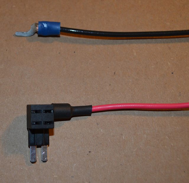
Here's a teaser pic before heading out for the night. Soldered on the right, non-soldered on the left.
Here's a teaser pic before heading out for the night. Soldered on the right, non-soldered on the left.
 03-30-2015, 03:59 PM
#14
Tech Contributor
Thread Starter
Member Since: Jan 2006
Location: Saint Louis MO
Posts: 4,761
Likes: 0
Received 219 Likes
on
110 Posts
St. Jude Donor '14-'15
Getting part numbers on switches while I'm out. O'Reilly has the best selection of the smaller lighted round type. RadioShack has a good 12v 25A plain switch, but who knows how many stores will be left of those soon.
AutoZone has terrible inventory management on the website lately - none of the part numbers will show up. Have to go to the store to even get a picture of something.
AutoZone has terrible inventory management on the website lately - none of the part numbers will show up. Have to go to the store to even get a picture of something.
03-30-2015, 08:03 PM
#15
Tech Contributor
Thread Starter
Member Since: Jan 2006
Location: Saint Louis MO
Posts: 4,761
Likes: 0
Received 219 Likes
on
110 Posts
St. Jude Donor '14-'15
I've been able to source everything at AutoZone after going to a few and getting all of the needed part numbers, etc. No more Lowes, etc.
They have everything needed, including a good 25A switch that's available with red or blue LED. Looks great, and only requires one additional wire to a nearby ground. It's a stocked part, so no worry of being discontinued. I bought all of the items needed to make sure I could duplicate the tutorial start to finish before posting it.
I will delete these little updates after putting the major one up here shortly.
It was a little irresponsible to put the first post up and then go on an escapade for making it easier... Overall, though, I've made this accessible to just about anyone with a C7, a pair of hands, and the ability to go to any AutoZone. That's kind of my goal with these DIYs, after all.
 03-30-2015, 11:00 PM
#17
Tech Contributor
Thread Starter
Member Since: Jan 2006
Location: Saint Louis MO
Posts: 4,761
Likes: 0
Received 219 Likes
on
110 Posts
St. Jude Donor '14-'15
Parts list is done, and all pictures have been added with regard to that list.
Hopefully this helps you guys find these items - they're all really easy to find, except for perhaps those which are not shown online.
Adding switch info and pictures now, along with some nerdy resistor info.
Hopefully this helps you guys find these items - they're all really easy to find, except for perhaps those which are not shown online.
Adding switch info and pictures now, along with some nerdy resistor info.
03-31-2015, 03:28 AM
#19
Tech Contributor
Thread Starter
Member Since: Jan 2006
Location: Saint Louis MO
Posts: 4,761
Likes: 0
Received 219 Likes
on
110 Posts
St. Jude Donor '14-'15
Soldered versions added (pics & walkthrough). Pics of no-solder version added, walkthrough being revised.
Preview shots added to the switch post.
Preview shots added to the switch post.
03-31-2015, 07:00 AM
#20
Race Director


Member Since: Feb 2014
Location: Center of the Universe, Alabama
Posts: 12,243
Received 95 Likes
on
41 Posts
Great info...great write up.
I had similar thoughts but with one difference, I wanted to keep the relocated 20 amp NPP fuse under the hood and on the +12v side of the wiring coming from the fuse panel. I'm a little **** and my reason being that if the wiring coming into the cabin ever chaffed enough to short to ground, that it would be protected. I'll explain what I mean by "+12v side of the wiring coming from the fuse panel". With the NPP fuse removed and with the car running, you take a volt meter and check each of the two fuse socket pin holes, one of them will measure +12 volts to ground. That's the wire I'd want the new fuse socket to be on.
Again kudos.