
NPP Reverse-Engineered - Full Open/Close, Non-Factory-NPP Retrofit
 06-02-2015, 10:32 PM
#61

Sorry, I was looking at the controller they made for a non-NPP car. If you have a non-NPP car, you buy the actuators + a controller from them in addition to their exhaust system.
They have this very tiny controller (it looks to be about 2in square) that taps into a blue and white wire from the CCM bundle which I suspect means some kind of bus (CAN?) which they can snoop signals from. They also then have cables that run to the actuators.
It is this controller I'd like to see - I imagine they have a microcontroller of some kind to interface with the CCM then they of course also have the solution you've reverse engineered to manage the actuators.
Their solution is interesting because it shows you can add NPP to a non-NPP car with just the stock NPP exhaust (including actuators) and their controller.
 06-02-2015, 10:43 PM
#62
Tech Contributor
Thread Starter
Member Since: Jan 2006
Location: Saint Louis MO
Posts: 4,761
Likes: 0
Received 218 Likes
on
110 Posts
St. Jude Donor '14-'15
Sorry, I was looking at the controller they made for a non-NPP car. If you have a non-NPP car, you buy the actuators + a controller from them in addition to their exhaust system.
They have this very tiny controller (it looks to be about 2in square) that taps into a blue and white wire from the CCM bundle which I suspect means some kind of bus (CAN?) which they can snoop signals from. They also then have cables that run to the actuators.
It is this controller I'd like to see - I imagine they have a microcontroller of some kind to interface with the CCM then they of course also have the solution you've reverse engineered to manage the actuators.
Their solution is interesting because it shows you can add NPP to a non-NPP car with just the stock NPP exhaust (including actuators) and their controller.
They have this very tiny controller (it looks to be about 2in square) that taps into a blue and white wire from the CCM bundle which I suspect means some kind of bus (CAN?) which they can snoop signals from. They also then have cables that run to the actuators.
It is this controller I'd like to see - I imagine they have a microcontroller of some kind to interface with the CCM then they of course also have the solution you've reverse engineered to manage the actuators.
Their solution is interesting because it shows you can add NPP to a non-NPP car with just the stock NPP exhaust (including actuators) and their controller.
The rest is the same - power, ground, 20A fuse tap, pins 1,2, and 4 to the actuators, etc.
Either one is capable of allowing non-NPP cars to convert to NPP systems - it comes down to what type of control you'd like. Theirs will be automatic (controlled by gear/speed/etc), whereas this one will be manual (controlled via a switch for instant-open/close).
Still nice to have a choice like this out there, and it's hard to get your feelings hurt when the bottom line is for charity, anyhow.

Price point has been the most difficult part of this thus far, as I don't yet have a good gauge on projected volume of sales yet. Since I don't have distribution (as this is non-profit), I have to take a risk without reward. I'll be interested to see what the MSRP on that unit is to make sure we can effectively produce these in small batches and still generate a good stream of revenue for St. Jude's.
 06-02-2015, 11:02 PM
#63
Tech Contributor
Thread Starter
Member Since: Jan 2006
Location: Saint Louis MO
Posts: 4,761
Likes: 0
Received 218 Likes
on
110 Posts
St. Jude Donor '14-'15
Well, at least I know what they're using now. Blue is High Speed GMLAN Serial Data (+), and White is High Speed GMLAN Serial Data (-).
Now I'm curious if it's inductive or has the standard wire tap. Inductive would be very trick, but expensive.
Hey, at least I feel better now that we know they're not the same circuit designs.
Now I'm curious if it's inductive or has the standard wire tap. Inductive would be very trick, but expensive.
Hey, at least I feel better now that we know they're not the same circuit designs.
06-03-2015, 12:59 AM
#64
Tech Contributor
Thread Starter
Member Since: Jan 2006
Location: Saint Louis MO
Posts: 4,761
Likes: 0
Received 218 Likes
on
110 Posts
St. Jude Donor '14-'15
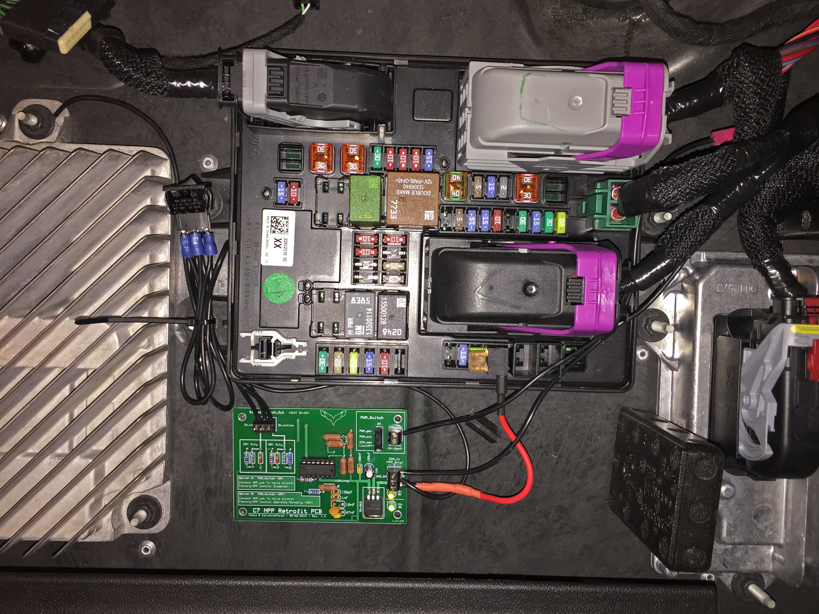
I went ahead and posted some install pics (on the front page) of the first production boards (v1.4) just so there was no bad blood about 'who-installed-what-where-first'. 
06-03-2015, 05:41 AM
#65
Tech Contributor
Thread Starter
Member Since: Jan 2006
Location: Saint Louis MO
Posts: 4,761
Likes: 0
Received 218 Likes
on
110 Posts
St. Jude Donor '14-'15
Due to a few questions and PMs, I've created a very short, impromptu video to show what exactly this mod does and does not do:
The pictures added to the front page have far more detail. Forgive the shakiness of the video - the iPhone 6+ in 60FPS seems to have no image stabilization, and YouTube's is terrible.
Anyway, it's in 1080p60 directly at YouTube, or this small window here:
What you're seeing is exactly what this circuit does - full manual control of the NPP valves. In addition, this does not require a CCM signal from an NPP-equipped vehicle. Translation, you can use this to retrofit all day long, or to take INSTANT and COMPLETE control of your NPP valves.
You will notice that I include a flurry of switching in there to show the response time on the valve. Actuation time is between 200ms and 400ms depending on direction.
What this does do:
What this does not do:
Hope that clears some things up for some of you.
The pictures added to the front page have far more detail. Forgive the shakiness of the video - the iPhone 6+ in 60FPS seems to have no image stabilization, and YouTube's is terrible.
Anyway, it's in 1080p60 directly at YouTube, or this small window here:
What you're seeing is exactly what this circuit does - full manual control of the NPP valves. In addition, this does not require a CCM signal from an NPP-equipped vehicle. Translation, you can use this to retrofit all day long, or to take INSTANT and COMPLETE control of your NPP valves.
You will notice that I include a flurry of switching in there to show the response time on the valve. Actuation time is between 200ms and 400ms depending on direction.
What this does do:
- Allows the user to have a manual control switch nearby - ALWAYS OFF / ALWAYS ON.
- Allows the user to toggle a switch on the board (or optional second breakout switch) to switch between factory/OEM NPP and the circuit generator NPP.
- Allows NPP owners with track decibel requirements to close the valves during certain stretches to maintain qualification sound levels.
- Allows instantaneous ON/OFF - perfect for the short-notice police moments with a blown 416.
- Allows spring to move valve to default open position on Ignition OFF.
What this does not do:
- Does not interact with the CANBUS or GMLAN BUS. This is a 'dumb' circuit, and knows only how to generate two precise signals (OPEN and CLOSE) in pulse wave.
- Does not allow for retrofitting NPP with AUTOMATIC controls. (Does allow for retrofitting with manual switch as previously stated).
- Does not become self aware... that we know of, yet.
Hope that clears some things up for some of you.
06-03-2015, 05:49 AM
#66
Tech Contributor
Thread Starter
Member Since: Jan 2006
Location: Saint Louis MO
Posts: 4,761
Likes: 0
Received 218 Likes
on
110 Posts
St. Jude Donor '14-'15
Last note for the evening / morning - I am working out pricing with all of the different parts suppliers since this is now a 100% charity drive.
All proceeds, minus the cost of parts, shipping supplies, and actual shipping will be sent through our St. Jude's organizer here. There will be a small assembly fee for those who want a fully finished board that's plug-and-play out of the box, but it will include testing, and will also be passed along directly to our charity.
The other manufacturer has a good-looking product, but the connectors/boxes/etc. do drive up the price with every addition. We (I) have to make sure I'm being responsible with spending, as well as making sure these sell (in order to actually get the money moving to charity). Otherwise, I'll be stuck with a bunch of boards.
I believe I will design an off-board (second board is more accurate) solution for retrofitting (routing high-amp power away from the signals), as to defray cost away from those that already have NPP, and do not require additional cables. Keep in mind that unlike any other solution on the market, this was made with NPP owners in mind.
Final note - v1.7 micro is well over 60% smaller than the first revision - absolutely no worries with finding a place for it back there.
06-03-2015, 11:25 AM
#67

Thanks for answering that, guys. Been at the wake all day.
Speaking for all exhaust types, assuming you wanted to cobble together 'brand-X' dual outlet mufflers with the factory spring-loaded butterflies (which are not sold alone - you'd have to cut apart an exhaust) on one side, this would make it possible. However, that's an awful lot of work. Corsa is out due to the single outlet.
Speaking for all exhaust types, assuming you wanted to cobble together 'brand-X' dual outlet mufflers with the factory spring-loaded butterflies (which are not sold alone - you'd have to cut apart an exhaust) on one side, this would make it possible. However, that's an awful lot of work. Corsa is out due to the single outlet.
06-03-2015, 11:45 AM
#69
I was seriously hoping for a circuit that would take my input as more of a request than a command. Like my wife.
 06-03-2015, 12:00 PM
#70
06-03-2015, 03:48 PM
#71
Race Director


Member Since: Feb 2014
Location: Center of the Universe, Alabama
Posts: 12,243
Received 95 Likes
on
41 Posts
So if one did want to add NPP functionality to a non-compatible NPP exhaust, you would just need to cut the tips off the NPP exhaust and weld them on to the aftermarket mufflers. That would explain why this could not work on the Corsa because they have single exit pipes coming out of each muffler. Ok I think I'm clear now, thanks!
06-03-2015, 06:30 PM
#72
Tech Contributor
Thread Starter
Member Since: Jan 2006
Location: Saint Louis MO
Posts: 4,761
Likes: 0
Received 218 Likes
on
110 Posts
St. Jude Donor '14-'15
Not touching that second part!

So if one did want to add NPP functionality to a non-compatible NPP exhaust, you would just need to cut the tips off the NPP exhaust and weld them on to the aftermarket mufflers. That would explain why this could not work on the Corsa because they have single exit pipes coming out of each muffler. Ok I think I'm clear now, thanks!
 06-03-2015, 07:05 PM
#73
Tech Contributor
Thread Starter
Member Since: Jan 2006
Location: Saint Louis MO
Posts: 4,761
Likes: 0
Received 218 Likes
on
110 Posts
St. Jude Donor '14-'15
A few updates for today:
First, (while we've discussed how the products are completely different) after learning of the prices for the other discussed retrofit device, I'm no longer worried about having to abandon the project due to cost concerns. I think many of you will be pleasantly surprised with the price, assuming we can wrap up the last part of manufacturing.
Second, I took a good drive today with the newer prototype to try to get some video of the mod doing its intended job in motion. Track mode, PTM engaged, blasting through corners, and flipping the tiny switch to close the valves. Nothing like a vision coming to reality.
Something to keep in mind - all versions of this mod are identical in function. The only difference is size and connectors. As you can see from the pictures, there's plenty of room back there. Getting these designs smaller and smaller has been a lot of fun (hey, most engineers are geeks), but the original v1.4 size has been a nice, comfortable size for DIY soldering, etc. We'll see what the final size will be shortly - I'm afraid I'm starting to make it too small with the Micro... Had lots of fun designing it, though!
I will post the video as soon as it's done encoding. It illustrates the point a little better than just a couple valves flapping open and closed. Still, it's come a long way from a benchtop breadboard turning a spindle.
06-03-2015, 07:07 PM
#74
I'm Batman..
Pro Mechanic

Member Since: Apr 2014
Location: Lehigh Acres FL
Posts: 6,130
Received 908 Likes
on
561 Posts
Tech Contributor

Due to a few questions and PMs, I've created a very short, impromptu video to show what exactly this mod does and does not do:
The pictures added to the front page have far more detail. Forgive the shakiness of the video - the iPhone 6+ in 60FPS seems to have no image stabilization, and YouTube's is terrible.
Anyway, it's in 1080p60 directly at YouTube, or this small window here:
What you're seeing is exactly what this circuit does - full manual control of the NPP valves. In addition, this does not require a CCM signal from an NPP-equipped vehicle. Translation, you can use this to retrofit all day long, or to take INSTANT and COMPLETE control of your NPP valves.
You will notice that I include a flurry of switching in there to show the response time on the valve. Actuation time is between 200ms and 400ms depending on direction.
What this does do:
What this does not do:
Hope that clears some things up for some of you.
The pictures added to the front page have far more detail. Forgive the shakiness of the video - the iPhone 6+ in 60FPS seems to have no image stabilization, and YouTube's is terrible.
Anyway, it's in 1080p60 directly at YouTube, or this small window here:
What you're seeing is exactly what this circuit does - full manual control of the NPP valves. In addition, this does not require a CCM signal from an NPP-equipped vehicle. Translation, you can use this to retrofit all day long, or to take INSTANT and COMPLETE control of your NPP valves.
You will notice that I include a flurry of switching in there to show the response time on the valve. Actuation time is between 200ms and 400ms depending on direction.
What this does do:
- Allows the user to have a manual control switch nearby - ALWAYS OFF / ALWAYS ON.
- Allows the user to toggle a switch on the board (or optional second breakout switch) to switch between factory/OEM NPP and the circuit generator NPP.
- Allows NPP owners with track decibel requirements to close the valves during certain stretches to maintain qualification sound levels.
- Allows instantaneous ON/OFF - perfect for the short-notice police moments with a blown 416.
- Allows spring to move valve to default open position on Ignition OFF.
What this does not do:
- Does not interact with the CANBUS or GMLAN BUS. This is a 'dumb' circuit, and knows only how to generate two precise signals (OPEN and CLOSE) in pulse wave.
- Does not allow for retrofitting NPP with AUTOMATIC controls. (Does allow for retrofitting with manual switch as previously stated).
- Does not become self aware... that we know of, yet.
Hope that clears some things up for some of you.
 06-03-2015, 07:19 PM
#75
Tech Contributor
Thread Starter
Member Since: Jan 2006
Location: Saint Louis MO
Posts: 4,761
Likes: 0
Received 218 Likes
on
110 Posts
St. Jude Donor '14-'15
There are two parts to this answer. The valves, themselves, on a factory NPP vehicle are powered by a fuse that is switched with full ignition. Hence, it barks sharply right before closing on a normal NPP car (no mod, etc).
The answer is more complicated for owners of factory NPP cars, but you're not in that set, so the news is a lot better.
Since you're retrofitting, the valves/actuators are pulling power from a switched circuit that goes hot on the first button press (I usually call it pre-ignition or aux) - that's the same power flowing to this circuit board. So, assuming you have the switch in the correct direction, those valves will close as soon as you hit the start/ignition button the first time.
I don't know what the voltage drop is like when starting the car with regard to the rear fuse box, but I'm going to assume there will be at least 10v of charge left to power the circuit, and hold the motors in place.
So, long answer to a simple question... Yes, you will be able to start your car with the valves closed. You will need to make sure to press the start/ignition button once BEFORE putting your foot on the brake (and clutch if applicable) to go into aux mode. Otherwise, the car just goes right into fire-up mode, and most likely won't have time to give the circuit and valves the juice they need to actuate before turning over. Could be wrong, though, and it may just be near-instantaneous. That would be an unexpected bonus!
06-03-2015, 08:01 PM
#76
I go through and hand-pick the op-amps with the lowest aptitude. That way, they're more likely to keep in line and not rebel.
Not touching that second part!
You've got it! Assuming there was a Corsa muffler that worked for us with dual outlets, that's exactly what you'd be able to do. The Corsa sound, though, is most likely related to the way the single pipe travels/is baffled, etc. I love that sound, too! Just can't give up the NPP. Maybe we'll figure out a good dual exit muffler that keeps a similar sound signature.
When they open, the exhaust gases take the more direct route of going straight out versus traveling through larger perforations in the tube, and flowing to smaller perforations in the inside tube and then out to the atmosphere. The direct path also skips most of the baffling (not all, of course), making the exhaust much louder.
 06-03-2015, 08:04 PM
#77
Tech Contributor
Thread Starter
Member Since: Jan 2006
Location: Saint Louis MO
Posts: 4,761
Likes: 0
Received 218 Likes
on
110 Posts
St. Jude Donor '14-'15
06-03-2015, 08:21 PM
#78
I'm Batman..
Pro Mechanic
Member Since: Apr 2014
Location: Lehigh Acres FL
Posts: 6,130
Received 908 Likes
on
561 Posts
Tech Contributor
Got you covered on that! I have a 22-month old, so I get it - trust me.
There are two parts to this answer. The valves, themselves, on a factory NPP vehicle are powered by a fuse that is switched with full ignition. Hence, it barks sharply right before closing on a normal NPP car (no mod, etc).
The answer is more complicated for owners of factory NPP cars, but you're not in that set, so the news is a lot better.
Since you're retrofitting, the valves/actuators are pulling power from a switched circuit that goes hot on the first button press (I usually call it pre-ignition or aux) - that's the same power flowing to this circuit board. So, assuming you have the switch in the correct direction, those valves will close as soon as you hit the start/ignition button the first time.
I don't know what the voltage drop is like when starting the car with regard to the rear fuse box, but I'm going to assume there will be at least 10v of charge left to power the circuit, and hold the motors in place.
So, long answer to a simple question... Yes, you will be able to start your car with the valves closed. You will need to make sure to press the start/ignition button once BEFORE putting your foot on the brake (and clutch if applicable) to go into aux mode. Otherwise, the car just goes right into fire-up mode, and most likely won't have time to give the circuit and valves the juice they need to actuate before turning over. Could be wrong, though, and it may just be near-instantaneous. That would be an unexpected bonus!
 06-03-2015, 08:23 PM
#79
Tech Contributor
Thread Starter
Member Since: Jan 2006
Location: Saint Louis MO
Posts: 4,761
Likes: 0
Received 218 Likes
on
110 Posts
St. Jude Donor '14-'15
well that's is just splendid news! Since I am a short guy at 5'6", I use my memory seats to my advantage and when I get in the car I press my start button to "get me into position" and then I start the car. So, that sounds that will work better than OEM as far as I am concerned!
06-03-2015, 08:36 PM
#80
Safety Car

I know this is not exactly the core part of your design, but what about the switch/button itself? What does it look like? Where does it mount?
Say I'm manhandling the car around a track, is it easy to reach and operate between gearshifts and steering inputs?
Say I'm manhandling the car around a track, is it easy to reach and operate between gearshifts and steering inputs?

