
NPP Reverse-Engineered - Full Open/Close, Non-Factory-NPP Retrofit
 04-28-2015, 05:50 AM
#1
Tech Contributor
Thread Starter
Member Since: Jan 2006
Location: Saint Louis MO
Posts: 4,761
Likes: 0
Received 218 Likes
on
110 Posts
St. Jude Donor '14-'15
Welp, here it is!
This mod is, quite simply, the 'full version' of the previously-posted NPP on/off control. Rather than a simple fuse relocation, this mod re-creates the necessary PWM signals that allow the NPP actuators to open and close the NPP butterfly valves. Much like the other version, this version uses a switch to both open and close the valves - however, this mod allows those changes to be made at any point, in any mode, and even without a factory-equipped NPP CCM. What does this mean? It means the NPP retrofit mod that everyone has been waiting for is finally here!

Purpose/Scope of Project:
This project was taken up for dual purposes:
1) Offering an option for owners of tracked C7s (with NPP) to force the NPP valves closed to meet sound regulations, and
2) Offering an option for C7 owners to retrofit and install an NPP exhaust system (with NPP rear exhaust valves) on a car that was not factory-equipped with the NPP option.
Now, let's have a little question and answer session!
Why are you making a big deal out of this? You could have just done this with a servo controller...
Well, there's a reason that it took this long, and it wasn't a $7 part available on Amazon. In fact, it wasn't any of the 13 controllers I purchased on Amazon. Nor was it any of the 6 devices I ordered from DealExtreme out of Hong Kong. Why did none of those work?
Simply put, the 555 is not appropriate, even with a 393 or similar, for this circuit. The overshoot, jitter, and overall inaccuracy of the astable 555 circuit make it highly unsuitable. These devices can, indeed, cause the valve to turn, but only for a small amount of time, and not in the correct fashion. The internal logic on both the factory-NPP CCM and the valves is very precise, and expects a very tight response 'window', along with several other variables. Assuming we were able to regulate the 555 circuit using multiples (which I did with both single and dual 556s), we run smack into another wall - the signal is not a true square wave. It is a positive-pulse wave extending from 0mV to 9V - a typical square wave would see this as -4.5V to 4.5V. A function generator normally can set an offset on a square wave, but that doesn't help much in the IC world, unless we want to carry AC-powered function generators in our trunks.
There have been several other 'fun' lessons learned, including the problems with testing the valves in free-air. Without the torque being applied to the valve by the spring-loaded butterfly, the valve essentially loses the calibration performed on the vehicle by the CCM. This causes the valves to stop responding to typical PWM signals, and instead forces it into what I'm going to refer to as a linear voltage mode. In this state, the valve can be 'tripped' at different intervals (by adjusting frequency and duty cycle much like the cheap 555 controllers do) and voltage levels. This isn't really true control - you're essentially using an AED on the valve to get it to turn, and relying on different voltage patterns (not a specific voltage, mind you) to trigger the actuation. In one of my circuit examples that I will not be posting here (for reference, I have 11 circuits in total - this is the correct and final version), I was able to trip actuation when exceeding the threshold of 12.7v, and have it return at 13.2v. Can anyone guess the problem? When the car is running, there's almost no way of getting a swing all the way down to 12.7v to get the actuation to reset. I can continue going further into this, but it's just discussing the results of an incorrect avenue of study.
To really throw you for a loop, the valves actually carry voltage over Pin 2... Yep - the input pin. The voltage scales in a linear fashion with the supply voltage, and generally sits in the 8-12% region. This wreaks all sorts of havoc, as when you throw that back into the circuit, you cause further instability. So, we just put a diode in the... Oh, wait... Positive pulse 0v, meaning that even a 200mV Schottky is out. Damn the bad luck! Put this on a 555 circuit and watch the scope - that's just too much fun.
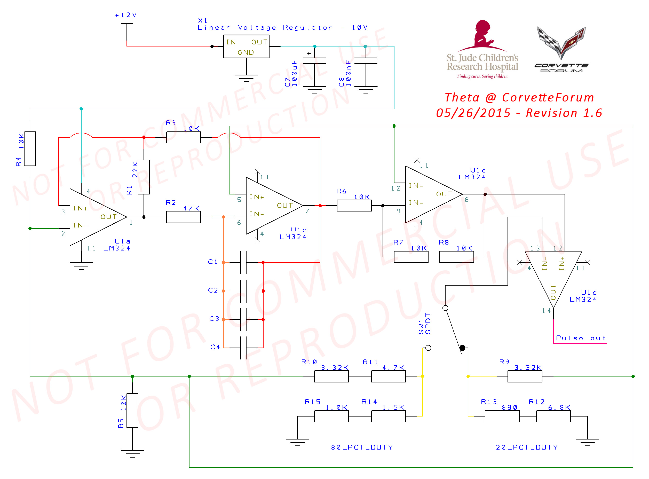
So, what are we left with here? Simply put, four op-amps are being used to create the logic circuit, with a fairly simple regulation circuit in front of it. We're using a single IC that actually contains 4 op-amps in a 14-pin package. For those not familiar with what an op-amp is, suffice it to say that it's the Swiss Army Knife of the EE world - you can really do just about anything you need with a pair (let alone two pair) of op-amps. The LM324 is an excellent choice here for many reasons, but I won't bore you. What we're using these four op-amps for is essentially creating 'parts' of the signal, refining, and smoothing. The first set creates a sawtooth/triangle by being configured as a trigger/integrator. The third is used as a comparator (against reference voltage). The fourth is just along for the ride... Kidding - we're using it here as a voltage follower/buffering device. What does this mean? These four op-amps are, in a properly-built circuit, creating the exact combination we need to replicate the factory PWM signals sent by a factory-NPP CCM.
I will post more technical information in a subsequent post. Getting late.
Why did you use fixed resistors? You know we'll need to use pots to tweak the signal!
Actually, I did use pots for the first three revisions. I calculated all of the needed resistances within a margin of +/- 0.01kΩ (10Ω), and used fixed 1% (or in some cases, tighter) metal film resistors to guarantee proper values. This eliminates any need for an end user (the majority of which are not engineers) to calibrate the device, or potentially cause any damage to the valves by feeding incorrect values. Additionally, I started out with most everything being adjustable (down to the LM317K voltage regulator). As the project dragged on, piece by piece, I exchanged variable components for fixed (of course, re-testing at each point).
Why did this take so long?
Honestly, there are probably several people along the way that just gave up because it's a terribly frustrating process. Between the unsuitability of the simple 555, the need for an exact timing, frequency, slew, etc. it can get a little disheartening. Also, there aren't many of us with the equipment to do this research outside of a lab. I ended up buying all of the equipment needed to make this project a reality, and it was far more expensive than I could have imagined it being.
Oh boy, now he's going to ask for money...
Well, I won't lie - when I first set out on this, I asked the administrators about getting crowdfunding together to pay for the needed equipment, parts, etc. That's when I thought I might have $2000 or so invested... Oh, if only that could have been the end of it. As it ended up, I needed to buy a newer digital oscilloscope (my Tek is wonderful, but PWM really sucks to measure on analog scopes - anybody with me there?), two function generators (there's a story there, but for another time), a variable linear power supply (needed a 10A capacity for inrush simulation), 19 (yes, really) different square wave/PWM pre-fab controllers, breadboards, stripboards, special order resistors, caps, connectors, etc. from Mouser, a CarDaq-Plus for GDS2 support (for doing valve re-learns), a new NPP exhaust with the valves (for testing, and this will be up for sale soon) and God knows what else along the way. One bright spot was already having GDS2 as part of my $3100/yr subscription to the GM Support Package - so, I didn't have to re-buy that. Small bit of sunshine. Turned out to be a lot more than I was expecting. Thankfully, a member here actually split the cost of the exhaust with me to help my up-front out-of-pocket costs. I think that puts me somewhere around $3200. 
But you're going to sell these, so you'll make that back pretty quick...
Actually, no. I don't want the legal hassles associated with the reverse engineering of a system (even though this was done on a personal vehicle without any intrusion into the module, itself), nor do I want to deal with any potential liability issues moving forward. I've decided to make this into a hybrid-DIY of sorts. Don't worry, I'll wait for you to stop facepalming.
Why would you do that? Seems dumb...
Well, here's the kicker... Here's where I ask you guys for something. I talked this over with the administrators, and we're all in agreement here. I'd very much like to see a return on this investment of time, money, frustration - you name it. I don't want the money, though. If this information helps you, even just a little (or, if you're just feeling sorry for me for jumping through flaming hoops), please make a donation to St. Jude's here:
Donate to St. Jude's (2015 Annual Fundraiser Thread).
It can be large, small, or anywhere in between - I don't have to know, I'm just going to leave that up to you.
I know that many of you already make a yearly donation (and for that I thank you), but consider this project separate from the normal yearly banner/tag we all get. Trust me, those kids need the money far more than I do. You can decide however much you want to donate, but it would make me extremely happy to know that the money, effort, time, etc. spent on trying to make a little 1.5" spindle turn 90-degrees for a month ended up yielding a positive result for a worthy cause.
Nice guilt trip! Now how do I buy one of these?
Well, I have that (sort of) covered. I have designed a custom 2-layer mini PCB that can be produced by ExpressPCB for $75/3 ($25 each), plus shipping to me (or anyone who wants to order these). In larger volume, I was given a quote of $575/50 for 2-day production, and $408/50 for 10-day production. Breaking it down further isn't much better - it's $336/20 boards for 10-day production. Anyway, I don't really want to end up being the middle-man here, so we'll all have to figure something out.
If that's not your speed, or you don't need a PCB to make things work (completely respect that, schematic is below), I have made a stripboard diagram, as well. The custom PCB is kind of fun, as it becomes a kit of sorts to assemble. Then again, some of my fondest childhood memories revolve around buying slot car parts at hobby shops to assemble faster cars with my dad, so I may not be quite right - engineers are a little off.
You'll also need the components (of course), and I have a full Mouser parts list available which will be posted shortly. The retro-fitters adding the valves to a non-NPP car will be thrilled to know what I've sourced the female valve weatherproof connectors, wiring lugs, and insulator boots for an OEM-quality exterior install.
I believe it goes without saying that soldering is required. We can try to figure out a plan for those of you who need this mod, but don't have the tools or ability to do this. I just don't want to find myself on the wrong side of anybody after this headache, but I'm always willing to help others here.
I will be fleshing out the following posts over the next day or so with more information. In the mean time, I will try my best to answer questions and respond to posts. I will begin by posting the schematics and a video showing the mod in action.
I also believe it goes without saying that I would prefer that my work not be used or reproduced in any commercial capacity (be it a device, concept, etc) without first contacting me. I'm sure there are grey areas of what I can reserve the rights to, and what GM retains ownership of, but I'd rather this effort not turn into a giant mess after all of the time and money spent. I'm sure everyone here can understand that.
Finally, the standard disclaimer (tweaked a little):
This information is neither endorsed by or property of Corvette Forum in any way/shape/form. All liability stemming from any actions taken in relation to this information is solely placed upon the user. You, as the user, are responsible for using this information in a safe and productive way. If, for any reason, you do not understand any part of this information, please seek a qualified engineer. All (reservable) rights are reserved by the author, and no warranty or guarantee of accuracy (either implicit or explicit) has been or will be given. This information is subject to change at any time, and most likely will have slight revisions made to the final designs.
I truly hope this makes some of you happy. I'm really hoping it makes a lot of you happy enough to donate, which in turn will make a lot of kids happy. As someone who is going to be starting round 3 of cancer/surgical treatment (due to previous surgical errors), and the father of a wonderful 20-month-old (damn, they grow up quick), I can't begin to imagine how the kids and parents that both need the help of and are helped by St. Jude's must feel. Helplessness and hopelessness are not feelings that any child (or parent) should have.
Progress Updates (as of 06/15/2015):
Test units (version 1.4) have been in use for nearly a month now with minor updates to cabling here and there. Troubleshooting has been minimal, with no major issues reported. Changing switch wiring to CAT5 allowed signal strength and integrity to remain constant. Other board changes done for size and space constraints. Idea for a two-board system were thrown around, but ultimately would raise the cost greatly.
I'd like to get more units out there and testing shortly - I may do another small run of newer boards with new connectors to test the retrofit valve design, as all testers thus far have had factory NPP.
DIY kit may be iffy at this point, due to inability to troubleshoot without having the built circuit on a scope to see what's going on if something goes wrong. Still happy to sell kits to EEs and those that have the ability to troubleshoot.
Since this is more of a 'hack' using frequencies to control the valves, there is a possibility for the valves to panic (not die), but we've still yet to see one of those happen. With the factory rate of panicing AFM valves being so high, it's surprising that the NPP doesn't act up as often (probably due to less heat and feedback, thanks to lacking a Pin 3 connection, and not being located directly over the transmission and forward of the mufflers).
This mod is, quite simply, the 'full version' of the previously-posted NPP on/off control. Rather than a simple fuse relocation, this mod re-creates the necessary PWM signals that allow the NPP actuators to open and close the NPP butterfly valves. Much like the other version, this version uses a switch to both open and close the valves - however, this mod allows those changes to be made at any point, in any mode, and even without a factory-equipped NPP CCM. What does this mean? It means the NPP retrofit mod that everyone has been waiting for is finally here!
Purpose/Scope of Project:
This project was taken up for dual purposes:
1) Offering an option for owners of tracked C7s (with NPP) to force the NPP valves closed to meet sound regulations, and
2) Offering an option for C7 owners to retrofit and install an NPP exhaust system (with NPP rear exhaust valves) on a car that was not factory-equipped with the NPP option.
Now, let's have a little question and answer session!
Why are you making a big deal out of this? You could have just done this with a servo controller...
Well, there's a reason that it took this long, and it wasn't a $7 part available on Amazon. In fact, it wasn't any of the 13 controllers I purchased on Amazon. Nor was it any of the 6 devices I ordered from DealExtreme out of Hong Kong. Why did none of those work?
Simply put, the 555 is not appropriate, even with a 393 or similar, for this circuit. The overshoot, jitter, and overall inaccuracy of the astable 555 circuit make it highly unsuitable. These devices can, indeed, cause the valve to turn, but only for a small amount of time, and not in the correct fashion. The internal logic on both the factory-NPP CCM and the valves is very precise, and expects a very tight response 'window', along with several other variables. Assuming we were able to regulate the 555 circuit using multiples (which I did with both single and dual 556s), we run smack into another wall - the signal is not a true square wave. It is a positive-pulse wave extending from 0mV to 9V - a typical square wave would see this as -4.5V to 4.5V. A function generator normally can set an offset on a square wave, but that doesn't help much in the IC world, unless we want to carry AC-powered function generators in our trunks.
There have been several other 'fun' lessons learned, including the problems with testing the valves in free-air. Without the torque being applied to the valve by the spring-loaded butterfly, the valve essentially loses the calibration performed on the vehicle by the CCM. This causes the valves to stop responding to typical PWM signals, and instead forces it into what I'm going to refer to as a linear voltage mode. In this state, the valve can be 'tripped' at different intervals (by adjusting frequency and duty cycle much like the cheap 555 controllers do) and voltage levels. This isn't really true control - you're essentially using an AED on the valve to get it to turn, and relying on different voltage patterns (not a specific voltage, mind you) to trigger the actuation. In one of my circuit examples that I will not be posting here (for reference, I have 11 circuits in total - this is the correct and final version), I was able to trip actuation when exceeding the threshold of 12.7v, and have it return at 13.2v. Can anyone guess the problem? When the car is running, there's almost no way of getting a swing all the way down to 12.7v to get the actuation to reset. I can continue going further into this, but it's just discussing the results of an incorrect avenue of study.
To really throw you for a loop, the valves actually carry voltage over Pin 2... Yep - the input pin. The voltage scales in a linear fashion with the supply voltage, and generally sits in the 8-12% region. This wreaks all sorts of havoc, as when you throw that back into the circuit, you cause further instability. So, we just put a diode in the... Oh, wait... Positive pulse 0v, meaning that even a 200mV Schottky is out. Damn the bad luck! Put this on a 555 circuit and watch the scope - that's just too much fun.
So, what are we left with here? Simply put, four op-amps are being used to create the logic circuit, with a fairly simple regulation circuit in front of it. We're using a single IC that actually contains 4 op-amps in a 14-pin package. For those not familiar with what an op-amp is, suffice it to say that it's the Swiss Army Knife of the EE world - you can really do just about anything you need with a pair (let alone two pair) of op-amps. The LM324 is an excellent choice here for many reasons, but I won't bore you. What we're using these four op-amps for is essentially creating 'parts' of the signal, refining, and smoothing. The first set creates a sawtooth/triangle by being configured as a trigger/integrator. The third is used as a comparator (against reference voltage). The fourth is just along for the ride... Kidding - we're using it here as a voltage follower/buffering device. What does this mean? These four op-amps are, in a properly-built circuit, creating the exact combination we need to replicate the factory PWM signals sent by a factory-NPP CCM.
I will post more technical information in a subsequent post. Getting late.
Why did you use fixed resistors? You know we'll need to use pots to tweak the signal!
Actually, I did use pots for the first three revisions. I calculated all of the needed resistances within a margin of +/- 0.01kΩ (10Ω), and used fixed 1% (or in some cases, tighter) metal film resistors to guarantee proper values. This eliminates any need for an end user (the majority of which are not engineers) to calibrate the device, or potentially cause any damage to the valves by feeding incorrect values. Additionally, I started out with most everything being adjustable (down to the LM317K voltage regulator). As the project dragged on, piece by piece, I exchanged variable components for fixed (of course, re-testing at each point).
Why did this take so long?
Honestly, there are probably several people along the way that just gave up because it's a terribly frustrating process. Between the unsuitability of the simple 555, the need for an exact timing, frequency, slew, etc. it can get a little disheartening. Also, there aren't many of us with the equipment to do this research outside of a lab. I ended up buying all of the equipment needed to make this project a reality, and it was far more expensive than I could have imagined it being.
Oh boy, now he's going to ask for money...
Well, I won't lie - when I first set out on this, I asked the administrators about getting crowdfunding together to pay for the needed equipment, parts, etc. That's when I thought I might have $2000 or so invested... Oh, if only that could have been the end of it. As it ended up, I needed to buy a newer digital oscilloscope (my Tek is wonderful, but PWM really sucks to measure on analog scopes - anybody with me there?), two function generators (there's a story there, but for another time), a variable linear power supply (needed a 10A capacity for inrush simulation), 19 (yes, really) different square wave/PWM pre-fab controllers, breadboards, stripboards, special order resistors, caps, connectors, etc. from Mouser, a CarDaq-Plus for GDS2 support (for doing valve re-learns), a new NPP exhaust with the valves (for testing, and this will be up for sale soon) and God knows what else along the way. One bright spot was already having GDS2 as part of my $3100/yr subscription to the GM Support Package - so, I didn't have to re-buy that. Small bit of sunshine.
Turned out to be a lot more than I was expecting. Thankfully, a member here actually split the cost of the exhaust with me to help my up-front out-of-pocket costs. I think that puts me somewhere around $3200. But you're going to sell these, so you'll make that back pretty quick...
Actually, no. I don't want the legal hassles associated with the reverse engineering of a system (even though this was done on a personal vehicle without any intrusion into the module, itself), nor do I want to deal with any potential liability issues moving forward. I've decided to make this into a hybrid-DIY of sorts. Don't worry, I'll wait for you to stop facepalming.
Why would you do that? Seems dumb...
Well, here's the kicker... Here's where I ask you guys for something. I talked this over with the administrators, and we're all in agreement here. I'd very much like to see a return on this investment of time, money, frustration - you name it. I don't want the money, though. If this information helps you, even just a little (or, if you're just feeling sorry for me for jumping through flaming hoops), please make a donation to St. Jude's here:
Donate to St. Jude's (2015 Annual Fundraiser Thread).
It can be large, small, or anywhere in between - I don't have to know, I'm just going to leave that up to you.
I know that many of you already make a yearly donation (and for that I thank you), but consider this project separate from the normal yearly banner/tag we all get. Trust me, those kids need the money far more than I do. You can decide however much you want to donate, but it would make me extremely happy to know that the money, effort, time, etc. spent on trying to make a little 1.5" spindle turn 90-degrees for a month ended up yielding a positive result for a worthy cause.
Nice guilt trip! Now how do I buy one of these?
Well, I have that (sort of) covered. I have designed a custom 2-layer mini PCB that can be produced by ExpressPCB for $75/3 ($25 each), plus shipping to me (or anyone who wants to order these). In larger volume, I was given a quote of $575/50 for 2-day production, and $408/50 for 10-day production. Breaking it down further isn't much better - it's $336/20 boards for 10-day production. Anyway, I don't really want to end up being the middle-man here, so we'll all have to figure something out.
If that's not your speed, or you don't need a PCB to make things work (completely respect that, schematic is below), I have made a stripboard diagram, as well. The custom PCB is kind of fun, as it becomes a kit of sorts to assemble. Then again, some of my fondest childhood memories revolve around buying slot car parts at hobby shops to assemble faster cars with my dad, so I may not be quite right - engineers are a little off.
You'll also need the components (of course), and I have a full Mouser parts list available which will be posted shortly. The retro-fitters adding the valves to a non-NPP car will be thrilled to know what I've sourced the female valve weatherproof connectors, wiring lugs, and insulator boots for an OEM-quality exterior install.
I believe it goes without saying that soldering is required. We can try to figure out a plan for those of you who need this mod, but don't have the tools or ability to do this. I just don't want to find myself on the wrong side of anybody after this headache, but I'm always willing to help others here.
I will be fleshing out the following posts over the next day or so with more information. In the mean time, I will try my best to answer questions and respond to posts. I will begin by posting the schematics and a video showing the mod in action.
I also believe it goes without saying that I would prefer that my work not be used or reproduced in any commercial capacity (be it a device, concept, etc) without first contacting me. I'm sure there are grey areas of what I can reserve the rights to, and what GM retains ownership of, but I'd rather this effort not turn into a giant mess after all of the time and money spent. I'm sure everyone here can understand that.
Finally, the standard disclaimer (tweaked a little):
This information is neither endorsed by or property of Corvette Forum in any way/shape/form. All liability stemming from any actions taken in relation to this information is solely placed upon the user. You, as the user, are responsible for using this information in a safe and productive way. If, for any reason, you do not understand any part of this information, please seek a qualified engineer. All (reservable) rights are reserved by the author, and no warranty or guarantee of accuracy (either implicit or explicit) has been or will be given. This information is subject to change at any time, and most likely will have slight revisions made to the final designs.
I truly hope this makes some of you happy. I'm really hoping it makes a lot of you happy enough to donate, which in turn will make a lot of kids happy. As someone who is going to be starting round 3 of cancer/surgical treatment (due to previous surgical errors), and the father of a wonderful 20-month-old (damn, they grow up quick), I can't begin to imagine how the kids and parents that both need the help of and are helped by St. Jude's must feel. Helplessness and hopelessness are not feelings that any child (or parent) should have.
Progress Updates (as of 06/15/2015):
Test units (version 1.4) have been in use for nearly a month now with minor updates to cabling here and there. Troubleshooting has been minimal, with no major issues reported. Changing switch wiring to CAT5 allowed signal strength and integrity to remain constant. Other board changes done for size and space constraints. Idea for a two-board system were thrown around, but ultimately would raise the cost greatly.
I'd like to get more units out there and testing shortly - I may do another small run of newer boards with new connectors to test the retrofit valve design, as all testers thus far have had factory NPP.
DIY kit may be iffy at this point, due to inability to troubleshoot without having the built circuit on a scope to see what's going on if something goes wrong. Still happy to sell kits to EEs and those that have the ability to troubleshoot.
Since this is more of a 'hack' using frequencies to control the valves, there is a possibility for the valves to panic (not die), but we've still yet to see one of those happen. With the factory rate of panicing AFM valves being so high, it's surprising that the NPP doesn't act up as often (probably due to less heat and feedback, thanks to lacking a Pin 3 connection, and not being located directly over the transmission and forward of the mufflers).
Last edited by Theta; 06-15-2015 at 04:20 PM.
 04-28-2015, 05:51 AM
#2
Tech Contributor
Thread Starter
Member Since: Jan 2006
Location: Saint Louis MO
Posts: 4,761
Likes: 0
Received 218 Likes
on
110 Posts
St. Jude Donor '14-'15
Reserved for Technical Information / Proofs of Concept.
Additional technical information being compiled for posting tonight.
This plays in 1080p60 (60fps) on YouTube if you'd care to watch it outside of the small player:
Valve Voltage Induction Into Circuit @ 80% Duty Cycle, 13.2V supply (Pin 2 input)
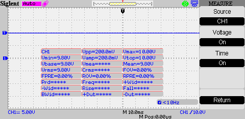
C7 NPP Vehicle CCM 80% Duty Cycle:
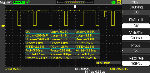
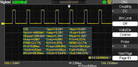
Signal Generator 80% Duty Cycle:

Retrofit Circuit 80% Duty Cycle:
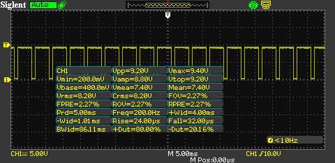
Retrofit Circuit 80% Duty Cycle (Valves Connected) - Notice the Voltage Difference:
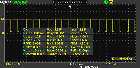
Valve Voltage Induction Into Circuit @ 20% Duty Cycle, 13.2V supply (Pin 2 input)
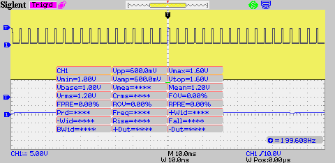
C7 NPP Vehicle CCM 20% Duty Cycle:
Signal Generator 20% Duty Cycle:
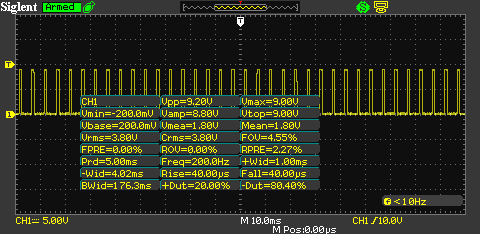
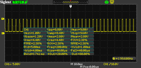
Retrofit Circuit 20% Duty Cycle:

Retrofit Circuit 20% Duty Cycle (Valves Connected) - Notice the Voltage Difference:
Additional technical information being compiled for posting tonight.
This plays in 1080p60 (60fps) on YouTube if you'd care to watch it outside of the small player:
Valve Voltage Induction Into Circuit @ 80% Duty Cycle, 13.2V supply (Pin 2 input)
C7 NPP Vehicle CCM 80% Duty Cycle:
Signal Generator 80% Duty Cycle:
Retrofit Circuit 80% Duty Cycle:
Retrofit Circuit 80% Duty Cycle (Valves Connected) - Notice the Voltage Difference:
Valve Voltage Induction Into Circuit @ 20% Duty Cycle, 13.2V supply (Pin 2 input)
C7 NPP Vehicle CCM 20% Duty Cycle:
Signal Generator 20% Duty Cycle:
Retrofit Circuit 20% Duty Cycle:
Retrofit Circuit 20% Duty Cycle (Valves Connected) - Notice the Voltage Difference:
Last edited by Theta; 04-30-2015 at 06:29 AM.
04-28-2015, 05:51 AM
#3
Tech Contributor
Thread Starter
Member Since: Jan 2006
Location: Saint Louis MO
Posts: 4,761
Likes: 0
Received 218 Likes
on
110 Posts
St. Jude Donor '14-'15
Schematics (ALL updated to 1.6 on 05/26/15):
Main Layout/Schematic Design Rev 1.6:
Note, I have used these two logos without explicit permission. I will remove either or both if asked to do so. Thank you.
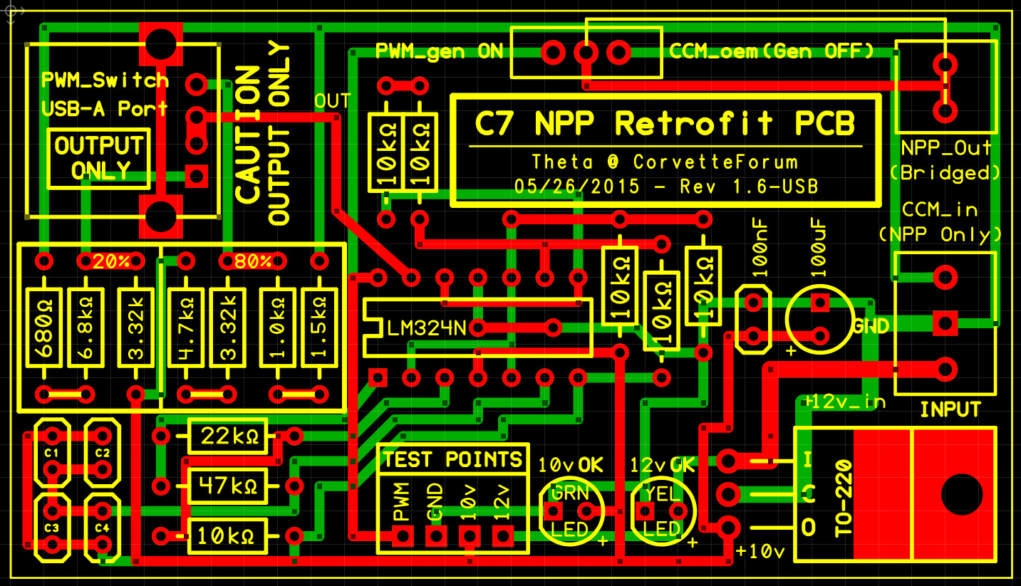
PCB Design Rev. 1.6-USB:
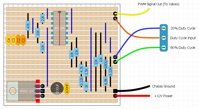
Stripboard Rev. 1.6:
C1-C4 values directly control the circuit frequency, and are stacked in parallel. These four capacitors must have a total initial value of 55.1uF, and sink to a floor no lower than 54.5 to maintain the proper frequency tolerance of 197Hz-203Hz.
I have tried to source caps with tight tolerances at these levels, but it has proved to be a futile effort. For now, I'm having to batch groups of caps by hand - a long and tedious process.
.
Main Layout/Schematic Design Rev 1.6:
Note, I have used these two logos without explicit permission. I will remove either or both if asked to do so. Thank you.
PCB Design Rev. 1.6-USB:
Stripboard Rev. 1.6:
C1-C4 values directly control the circuit frequency, and are stacked in parallel. These four capacitors must have a total initial value of 55.1uF, and sink to a floor no lower than 54.5 to maintain the proper frequency tolerance of 197Hz-203Hz.
I have tried to source caps with tight tolerances at these levels, but it has proved to be a futile effort. For now, I'm having to batch groups of caps by hand - a long and tedious process.
.
Last edited by Theta; 06-15-2015 at 04:05 PM.
The following users liked this post:
joemosfet (04-02-2018)
04-28-2015, 05:51 AM
#4
Tech Contributor
Thread Starter
Member Since: Jan 2006
Location: Saint Louis MO
Posts: 4,761
Likes: 0
Received 218 Likes
on
110 Posts
St. Jude Donor '14-'15
Due to a few questions and PMs, I've created a very short, impromptu video to show what exactly this mod does and does not do:
The pictures added to the front page have far more detail. Forgive the shakiness of the video - the iPhone 6+ in 60FPS seems to have no image stabilization, and YouTube's is terrible.
Anyway, it's in 1080p60 directly at YouTube, or this small window here:
What you're seeing is exactly what this circuit does - full manual control of the NPP valves. In addition, this does not require a CCM signal from an NPP-equipped vehicle. Translation, you can use this to retrofit all day long, or to take INSTANT and COMPLETE control of your NPP valves.
You will notice that I include a flurry of switching in there to show the response time on the valve. Actuation time is between 200ms and 400ms depending on direction.
What this does do:
What this does not do:
Hope that clears some things up for some of you.
The pictures added to the front page have far more detail. Forgive the shakiness of the video - the iPhone 6+ in 60FPS seems to have no image stabilization, and YouTube's is terrible.
Anyway, it's in 1080p60 directly at YouTube, or this small window here:
What you're seeing is exactly what this circuit does - full manual control of the NPP valves. In addition, this does not require a CCM signal from an NPP-equipped vehicle. Translation, you can use this to retrofit all day long, or to take INSTANT and COMPLETE control of your NPP valves.
You will notice that I include a flurry of switching in there to show the response time on the valve. Actuation time is between 200ms and 400ms depending on direction.
What this does do:
- Allows the user to have a manual control switch nearby - ALWAYS OFF / ALWAYS ON.
- Allows the user to toggle a switch on the board (or optional second breakout switch) to switch between factory/OEM NPP and the circuit generator NPP.
- Allows NPP owners with track decibel requirements to close the valves during certain stretches to maintain qualification sound levels.
- Allows instantaneous ON/OFF - perfect for the short-notice police moments with a blown 416.

- Allows spring to move valve to default open position on Ignition OFF.
What this does not do:
- Does not interact with the CANBUS or GMLAN BUS. This is a 'dumb' circuit, and knows only how to generate two precise signals (OPEN and CLOSE) in pulse wave.
- Does not allow for retrofitting NPP with AUTOMATIC controls. (Does allow for retrofitting with manual switch as previously stated).
- Does not become self aware... that we know of, yet.
Hope that clears some things up for some of you.
Last edited by Theta; 06-03-2015 at 05:42 AM.
04-28-2015, 05:52 AM
#5
Tech Contributor
Thread Starter
Member Since: Jan 2006
Location: Saint Louis MO
Posts: 4,761
Likes: 0
Received 218 Likes
on
110 Posts
St. Jude Donor '14-'15
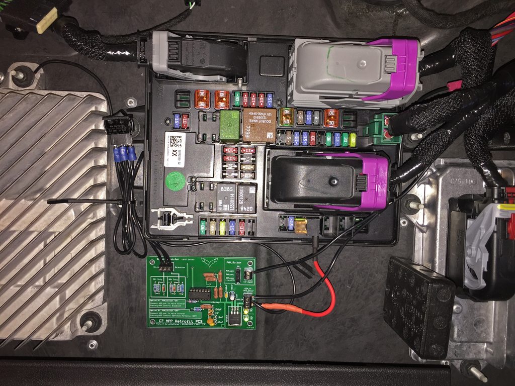
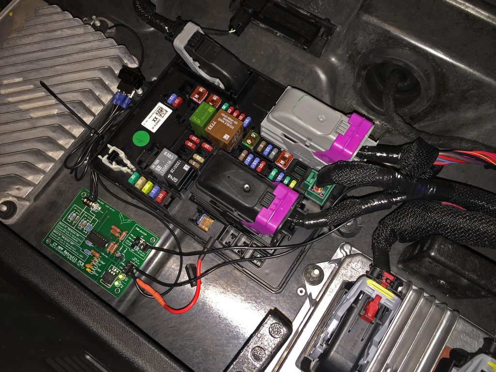
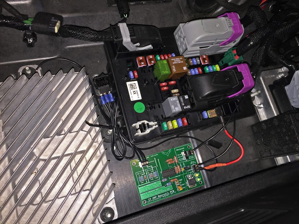
Rev. 1.4 Placement (Full Size Board) - Initial Test Fitting & Wiring (from 05/18):
Last edited by Theta; 06-03-2015 at 01:02 AM.
04-28-2015, 08:49 AM
#7
I'm Batman..
Pro Mechanic

Member Since: Apr 2014
Location: Lehigh Acres FL
Posts: 6,130
Received 908 Likes
on
561 Posts
Tech Contributor

Very, VERY impressive sir . I am indeed very thrilled you have a source for the actual weatherproof connectors for us non-NPP retrofitters! I'm going to be watching this thread like a hawk for more info so I can do this. 
Ant
. I am indeed very thrilled you have a source for the actual weatherproof connectors for us non-NPP retrofitters! I'm going to be watching this thread like a hawk for more info so I can do this. Ant
04-28-2015, 09:41 AM
#8
Race Director


Member Since: Feb 2014
Location: Center of the Universe, Alabama
Posts: 12,243
Received 95 Likes
on
41 Posts
This is great work. A true C7 "Mild to Wild" controller. Congratulations again.
Just a thought but what about putting your idea(s) up on the "KickStarter" website to recoup something? Maybe the admins would let you link your projects to the forum because they're so Corvette specific.
Just a thought but what about putting your idea(s) up on the "KickStarter" website to recoup something? Maybe the admins would let you link your projects to the forum because they're so Corvette specific.
Last edited by grandpawmoses; 04-28-2015 at 09:46 AM.
04-28-2015, 02:01 PM
#9
Safety Car


I have no need for this device given my usage of the car. But I'm impressed enough with what you've done, and the level of effort you put into it, that I'm going to make a small donation to St. Jude's anyway.
(Fond memories of building and improving slot cars, and Heathkits and Dynakits, help your cause, too.)
Nice work.
(Fond memories of building and improving slot cars, and Heathkits and Dynakits, help your cause, too.)
Nice work.
Last edited by meyerweb; 04-28-2015 at 02:03 PM.
04-30-2015, 01:54 AM
#10
Tech Contributor
Thread Starter
Member Since: Jan 2006
Location: Saint Louis MO
Posts: 4,761
Likes: 0
Received 218 Likes
on
110 Posts
St. Jude Donor '14-'15
Just finished and added a stripboard design, updated the PCB design further (rev 1.0b), working on the parts list - nearly complete for both sets.
Been filling other requests and catching up today.
Been filling other requests and catching up today.
05-01-2015, 06:53 AM
#11
Tech Contributor
Thread Starter
Member Since: Jan 2006
Location: Saint Louis MO
Posts: 4,761
Likes: 0
Received 218 Likes
on
110 Posts
St. Jude Donor '14-'15
Leaving this with Rev 1.0c tonight (I have a fun sleep pattern). Large changes with regard to series resistors. Mouser is having issues keeping the weird sizes in stock, and I don't want to run people into supply issues. Series resistors at =/<1% work just fine - just needed to make more room on the tiny boards.
These values were all built and tested this evening on a PCB and passed without issue. I will still tweak a few more things tomorrow, but we're pretty close to pulling the trigger on this.
I know a lot of you have contacted me, but I'll get that revised parts list up, and then take care of what needs to be ordered/shipped, built, etc.
PS: Special thanks to those of you who have commented, PMed, donated, etc. - means a lot to me.
05-07-2015, 04:57 PM
#12
Tech Contributor
Thread Starter
Member Since: Jan 2006
Location: Saint Louis MO
Posts: 4,761
Likes: 0
Received 218 Likes
on
110 Posts
St. Jude Donor '14-'15
Update on this - final revision boards (version 1.4) have been sent to production, and will arrive on Monday. Small batch was given priority (at a price premium) to get a quick turnaround.
All components are arriving tomorrow, and the first of the kits will be organized and/or assembled and shipped out. After that small batch is assembled, fully tested, and confirmed as being perfect, a much larger batch will be sent to production, and components will be purchased in bulk.
I'm still working out the distribution system on this - I have several vendors that would like to have the rights to distribute, but I need to focus on keeping the charity aspect in the forefront.
Many of you will be happy to know that I have different options setup for polycarbonate (clear or tinted) cases, normal lack cases, assembly options, and more to come. The boards look fantastic, and should look great in those clear cases - I took a long time on the finished models making sure everything was perfect both electrically and aesthetically.
I will update the main posts further - I've literally been spending weeks in SolidWorks and MultiSim perfecting everything. The newer circuits need to be posted.
Costs have not been released yet, as I've still trying to get a solid figure for bulk ordering prices. I am going to be offering a full assembly option for a nominal price that will go entirely to charity. Suffice to say that this should be comparable in price to the M2W without any options - nothing too crazy!
Thanks for all the positive interest, PMs, etc.
05-10-2015, 12:17 AM
#13
Tech Contributor
Thread Starter
Member Since: Jan 2006
Location: Saint Louis MO
Posts: 4,761
Likes: 0
Received 218 Likes
on
110 Posts
St. Jude Donor '14-'15
Well, here's a nice little weekend surprise / confirmation for you potential retrofitters out there!
Turns out that after searching for months and speaking to the OE manufacturer, I have finally found the correct female connectors with the leads and watertight seals (and yes, they properly latch, slide, and even lock). Just add wiring.
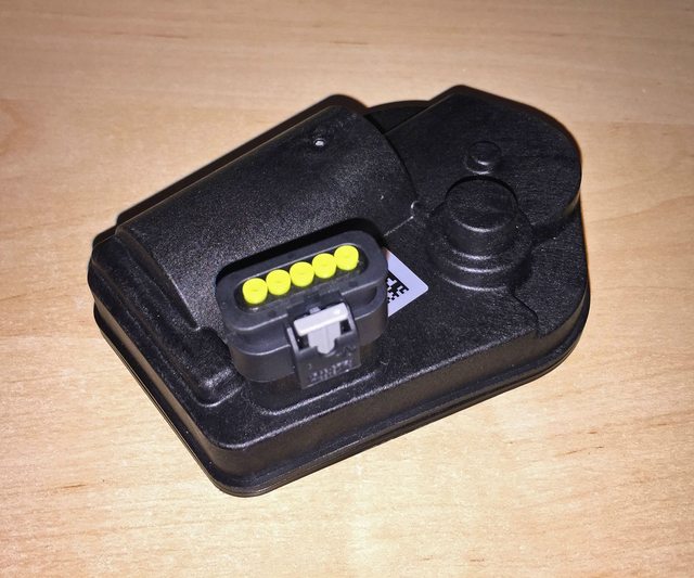
Turns out that after searching for months and speaking to the OE manufacturer, I have finally found the correct female connectors with the leads and watertight seals (and yes, they properly latch, slide, and even lock). Just add wiring.
05-10-2015, 02:10 AM
#14
I'm Batman..
Pro Mechanic
Member Since: Apr 2014
Location: Lehigh Acres FL
Posts: 6,130
Received 908 Likes
on
561 Posts
Tech Contributor
Well, here's a nice little weekend surprise / confirmation for you potential retrofitters out there!
Turns out that after searching for months and speaking to the OE manufacturer, I have finally found the correct female connectors with the leads and watertight seals (and yes, they properly latch, slide, and even lock). Just add wiring.

Turns out that after searching for months and speaking to the OE manufacturer, I have finally found the correct female connectors with the leads and watertight seals (and yes, they properly latch, slide, and even lock). Just add wiring.

The following users liked this post:
bustdnukles (03-18-2024)
05-10-2015, 05:58 PM
#15
Burning Brakes


Theta, awesome efforts expended on this project and I'm likely to be wanting this when my '16 C7 Z06 finally arrives.
Honestly I'm lost on all this intricate electrical stuff, glad to have individuals such as yourself who have this set of skills.
Honestly I'm lost on all this intricate electrical stuff, glad to have individuals such as yourself who have this set of skills.
 05-11-2015, 08:28 PM
#17
Tech Contributor
Thread Starter
Member Since: Jan 2006
Location: Saint Louis MO
Posts: 4,761
Likes: 0
Received 218 Likes
on
110 Posts
St. Jude Donor '14-'15
Thanks, Steve!
First (small set) of production boards will be arriving tomorrow. Pretty exciting to see a long-shot turn into reality.
First (small set) of production boards will be arriving tomorrow. Pretty exciting to see a long-shot turn into reality.
05-15-2015, 02:43 AM
#18
Tech Contributor
Thread Starter
Member Since: Jan 2006
Location: Saint Louis MO
Posts: 4,761
Likes: 0
Received 218 Likes
on
110 Posts
St. Jude Donor '14-'15
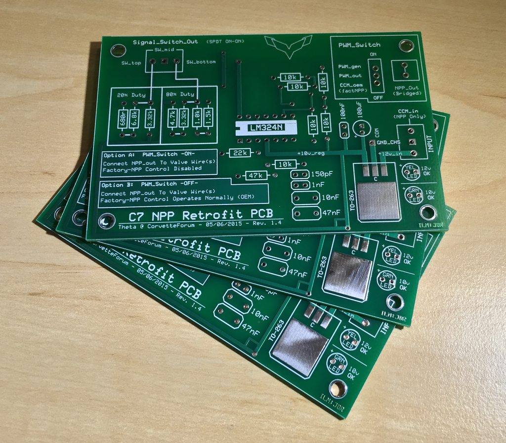
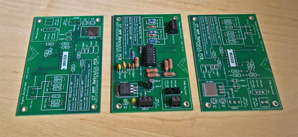
Sorry for the delay - these arrived on Tuesday, and the first 'production' board was built later in the day. After a few tweaks (the Vishay/Dale resistors were the incorrect size, and the cap tolerances were a bit too far off), the circuit was dead-on.
These turned out far better than I could have hoped for.
I am designing another (smaller) version at the moment, but that version removes the DIY aspect of this project. The size of these boards makes this a perfect (and easy) kit to put together if you're into that sort of fun.
Comments are welcome, as I'm curious if this size of PCB with thru-hole (easy) soldering appeals to more people than a smaller, ready-made SMD/SMT board design.
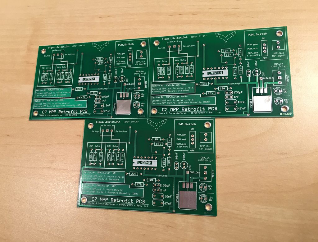
Board Arrival (first run of 3):
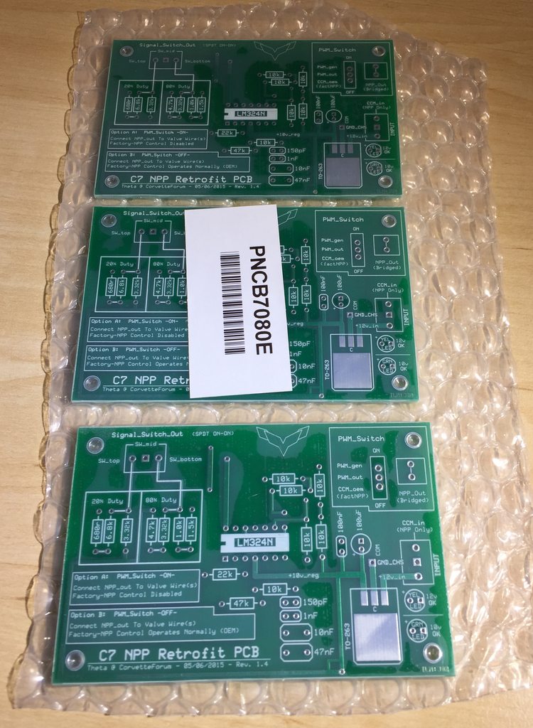
Unpacked:
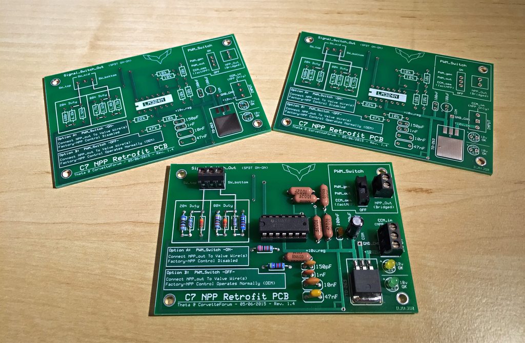
First Assembly & Test:
These turned out far better than I could have hoped for.
I am designing another (smaller) version at the moment, but that version removes the DIY aspect of this project. The size of these boards makes this a perfect (and easy) kit to put together if you're into that sort of fun.
Comments are welcome, as I'm curious if this size of PCB with thru-hole (easy) soldering appeals to more people than a smaller, ready-made SMD/SMT board design.
Board Arrival (first run of 3):
Unpacked:
First Assembly & Test:
05-15-2015, 01:44 PM
#19

[QUOTE=Theta;1589633517]Comments are welcome, as I'm curious if this size of PCB with thru-hole (easy) soldering appeals to more people than a smaller, ready-made SMD/SMT board design.
The DIY aspect appeals to me in the sense of a personal involvement to tinker for myself and others of your efforts to identify the need, design, prototype, and offer this cool device capability for charitable purposes.
Being familiar with the electronics business, it also makes sense only if there is not a dramatic cost difference from an SMT module as the base of a kit.
Count me in either way for a donation.
05-15-2015, 03:44 PM
#20
Advanced


[QUOTE=Theta;1589633517]
Comments are welcome, as I'm curious if this size of PCB with thru-hole (easy) soldering appeals to more people than a smaller, ready-made SMD/SMT board design.
Very professional looking. I am in for either the 'DIY' or preassembled version, whichever you decide to pursue. I'm in countdown mode as my order just went in for my car. I expect it in July.

