When you click on links to various merchants on this site and make a purchase, this can result in this site earning a commission. Affiliate programs and affiliations include, but are not limited to, the eBay Partner Network.
Also did you run across any issues with lash. I set my TDC and set my zero lash on the #1 exhaust, when i go to the intake side on #1 with the same pushrod length checker i have all kinds of play. I can feel the plunger on both compress and rebound.
As it is with no preload and splitting the difference between the 2 for zero lash, it seems like my rod length is around 8.0.
Originally Posted by SteveOO
My TX Speed kit came with stock length push rods. I think your rocker bolts are to long and bottoming out in head before the saddle gets tight. That's what mine did, using the new bolts in the kit. I used my bench grinder to shorten them, die to clean up starting thread. The aftermarket bolts have a bigger shoulder which I think you need to locate the rocker correctly.
Pretty sure my push rods are 7.800". I agree with above that you may have issues with the bolts. I also had to get the right bolts sent out and my kit was from a different vendor. Check you lash with the stock bolts and see if it corrects the issue. That will help to confirm if bolts are to blame..
Pretty sure my push rods are 7.800". I agree with above that you may have issues with the bolts. I also had to get the right bolts sent out and my kit was from a different vendor. Check you lash with the stock bolts and see if it corrects the issue. That will help to confirm if bolts are to blame..
My kit did not come with new rocker bolts, still using the stock rocker and bolts(plus trunion ipgrade). If i have seating issues with the rocker now i would think it would have been an issue also beforehand. I found out that the Jhonson lifters i am using has a different height though whch sould account for the over all length difference, mine came out to 7.970 at zero lash.
My kit did not come with new rocker bolts, still using the stock rocker and bolts(plus trunion ipgrade). If i have seating issues with the rocker now i would think it would have been an issue also beforehand. I found out that the Jhonson lifters i am using has a different height though whch sould account for the over all length difference, mine came out to 7.970 at zero lash.
I think the advertised lfiter cup height is lower than the factory lifters. That i have no problem with. Its the lack of consistency between the two. TSP is sending me some 8.0 rods and will see how it goes. Im hoping that it might just be the cup being a little sticky. Spring installed heights should be the same since it was just a spring change. That leaves the cam,lifter or rocker perch.
Fryant thanks for posting the cam/Head swap, awesome Wright up. I have been looking for a write up to do a cam swap on my 14 stingray. Do you have any sound clips of your car with the cam/Head swap, I would love to hear it. Thanks
Fryant thanks for posting the cam/Head swap, awesome Wright up. I have been looking for a write up to do a cam swap on my 14 stingray. Do you have any sound clips of your car with the cam/Head swap, I would love to hear it. Thanks
Thanks! Yes, I do. Its not the best vid, but you'll get the idea..
In the LS days it was important to center the timing cover with the GM tool, the crank pulley, or an ATI pin fixture before torquing to ensure no front main leak. Is that no longer important?
Crazy on the oil pump... did many LS jobs over the years and never an issue and never did any special alignment. Did pay attention to the pick-up o-ring.
In the LS days it was important to center the timing cover with the GM tool, the crank pulley, or an ATI pin fixture before torquing to ensure no front main leak. Is that no longer important?
the front and rear covers have dowel pins to ensure they are installed where they need to be.
All right, I�ll assume that at this point you have installed your cam phaser limiter, and performed your rocker arm trunnion upgrade. I�ll also assume your cylinder head valvetrain is upgraded and ready to go in both heads.
Now we will need to install the DoD delete kit. The Vengeance Racing DoD delete kit is simply a small aluminum plug kit that plugs the DoD/AFM oil galley towers to prevent oil from making its way up into the AFM hardware on the bottom side of the valley cover.
These plugs are soft aluminum so you simply need to hammer them into the holes for the AFM towers. I would recommend after getting the plug started in the hole, use a rag between the plug and the hammer to prevent marring up the top of the plugs. This is important later on to ensure the valley cover fits back on properly.
Once these are installed, now is a good time to clean out your bolt holes in the block and the thread of your bolts for the heads, timing cover, oil pan, etc. In the case of the head bolts, we will replace those with studs next so no worries about those. If you are in a pinch to find a proper thread chaser for the cylinder head bolt holes, you can actually take one of the old bolts, and use a cutoff wheel to carve a few cuts into the bolt long ways to make it simulate a thread tap. It works great actually.
Cleaning out the bolt holes is required as there will be old RTV sealants, and threadlocker present that will interfere with reassembly. Also you�ll need to make sure to clean off all the old RTV sealant from the mating surfaces of the block and parts we removed. Razor blades are your friend. I personally used an angle die grinder with a soft blue scuff pad but if you�ve never done that before don�t do it. You can easily take off too much material to cause an issue. You should use razor blades!
Once everything is all cleaned up, let�s install the new ARP head studs. Make sure you use the included ARP grease to grease up the threads on both ends of the studs. Install the studs by hand! Do not use a ratchet with an Allen bit! I chose to use some T-handle Allen wrenches to get the studs installed easier and evenly. Again, do not tighten the stud itself!
Once the head studs are all installed, we are ready to start greasing up our cam. Grease all contact points as I have done in the below picture. For this step, I prefer to use Redline Cam Paste, as it�s thicker than competitors engine assembly lube and will stay put until engine is started up.
Ok, now go put on a Metallica shirt because this is going to get heavy VERY CAREFULLY slide the cam into the block.
Now that the cam is installed, we need to install the cam retainer plate. To do this, apply BLUEthread locker to the bolts, install them and torque to 11 lb. ft. in the sequence shown.
Once the cam retainer plate is installed, grab your cam phaser, your new C5R timing chain, and you crank timing gear. First, put the crank timing gear on the front of the crankshaft, then put the timing chain on it, then lastly put the phaser gear inside the chain, and slide it all back.
If you did it correctly, you should be able to get the phaser onto the cam guide seated, and the timing should line up like how we took it off. If the timing does not line up, remove, adjust, install until you get it right. Now install the new CMP Actuator bolt through the phaser, and hand tighten for now.
In order to properly tighten this bolt, which is a one-time use Torque To Yield (TTY) bolt, we need to torque it to 48 lb. ft. first, and then turn the bolt an additional 90 degrees. To do this, you will need a digital angle gauge. I use a Brownline Digital Angle Gauge for this as pictured below. It�s magnetic and sticks right to the torque wrench. After I get to 48 lb. ft., and set my gauge for 90 degrees, I can then turn it exactly 90 degrees farther so it is torqued properly.
Alright, that�s all set. Now let�s go ahead and install our new lifters! Go ahead and grab them from the bowl of oil you had them stewing in, and slide them into the block one at a time ensuring the �roller� side is down.
After getting these installed, you need to install the new lifter trays, ensuring that they mate up to the lifters so that the lifters sit inside the trays. This is so the lifters do not turn sideways in the block. After these are in, install the 10MM bolts, one for each tray, (four total) to hold the lifter trays in place, and torque to 106 lb. in. each.
Now we will go ahead and install the fuel pump lifter back into the block, and torque the 13MM bolt to 106 lb. in.
Let�s go ahead and put on our cylinder heads gaskets next:
Man that�s friggin� gorgeous..
Now install your first cylinder head onto the block making sure you put it on the right side. Install the ARP nuts onto the studs, and torque these down in three equal phases using the below sequence to 115 lb. ft. This means do three passes, one complete pass at a time, to approx. 38 lb. ft., then to 76 lb. ft., then to 115 lb. ft. on the final pass.
Once this is completed, repeat the process for the other cylinder head.
Now that you�ve made it this far, it�s a great idea to consider �degreeing� your new cam. Doing this ensures that the cam �grind� you have is the same as what is on your cam card. If it�s off by 5-10 degrees and you didn�t degree the cam to figure this out, you could be chasing that problem extensively trying to figure it out later when the engine is assembled!
After both Cylinder heads are installed, you�re ready to tackle the oil pump. Grab your oil pump, and put it back on the front of the engine and finger screw in the bolts leaving them a pinch loose. Now you will need to torque the bolts to 18 lb. ft. in the below sequence WHILE KEEPING PRESSURE ON THE OIL PUMP AGAINST THE OIL PUMP ALIGNMENT TOOLS THE ENTIRE TIME!
Once the oil pump has been installed and torqued, go ahead and remove the oil pump alignment tools, we�re done with them. Now it�s time to tackle the front timing cover. While it�s not required, I would recommend replacing the front main seal while you have the front cover off, it�s cheap!
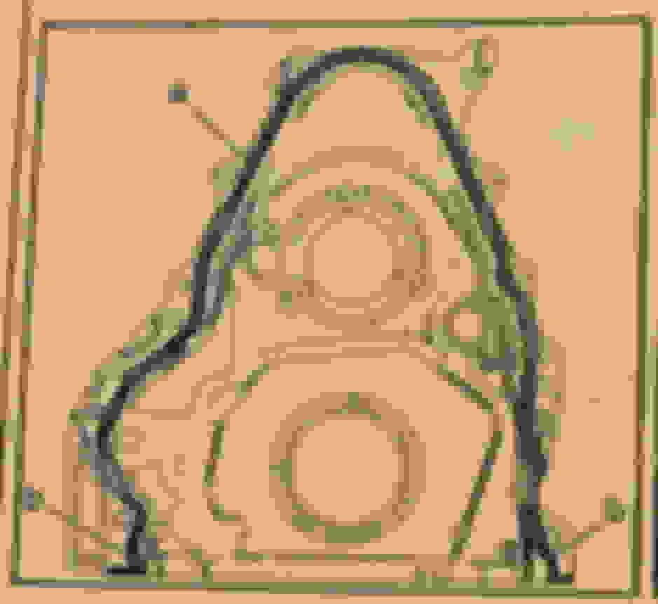
To install the RTV Sealant properly, you must follow the below diagram along with these instructions:
Apply a 3MM bead of RTV sealant to the area marked with a letter A, and apply a 5MM bead of RTV sealant to the area marked with the letter B. Install the cover and torque within 10 minutes of applying the bead!
Install the front cover onto the front of the engine, and finger screw all the bolts in evenly to draw the cover onto the block. Next, tighten them in sequence as shown below. For all numbers indicated by a �2 or 3� torque them to 18 lb. ft.
Once all bolts are torqued, make sure to reconnect the electrical connector to the oil pump on the underside of the engine!
Next is the oil pan. Install the oil pan as follows:
Apply a 3MM bead of RTV sealant to the area marked with a letter A, and apply a 5MM bead of RTV sealant to the area marked with the letter B. Install the cover and torque within 10 minutes of applying the bead!
Install all bolts for the oil pan finger tight and evenly to draw the oil pan on properly. Torque all bolts according to the below sequence. 13MM bolts (indicated in the below diagram with the number �2�) will be torqued to 106 lb. in. and all 10MM bolts (indicated in the below diagram with the number �3�) will be torqued to 18 lb. ft. No, you didn�t read that wrong, the smaller bolts have a higher torque.
Alrighty, now we need to also torque the bolts for the oil cooler bracket. Torque the 13MM bolts to 18 lb. ft., and torque the 11MM bolts to 89 lb. in.
Next you need to install the valley cover, but before doing so, do you need to install a lash cap for the fuel pump?! If you are using a cam with a 32% fuel lobe, then yes, you do need a lash cap.
Follow this guide to perform the proper measurements and get the right lash cap installed:
After you get your lash cap installed, go ahead and install the valley cover on the top of the valley, you may need a few taps from a rubber mallet to get it to seat properly with the new DoD delete plugs on the top of the block. They will sit inside some recessed areas in the bottom of the valley cover. Once the valley cover is sitting correctly, go ahead and install the bolts and torque them down a first pass to 106 lb. in., and then a final pass of 18 lb. ft. using the below sequence:
Now that the Valley cover it back on, we're going to move on to the final steps before we are ready to reinstall the motor. The last things to do are to install the pushrods and the rocker arms.
The pushrods are pretty straightforward. Install them one at a time, and ensure that they seat into the middle of the lifter properly.
Now go ahead and install the rocker arms and bolts finger tight for all valves. If you had your heads ported, then there is a good chance that the intake runners will have "holes" in them where the porting exposed the bottom of the rocker arm bolt holes. No problem if this is the case, you simply need to install the rocker arm bolts with thread SEALANT on them, NOT THREADLOCKER!
Ensure that the pushrods seat themselves alllll the way into the rocker arm properly. a good test is to use your fingers to twist the pushrod to ensure it rotates freely and is not binding on anything.
The rocker arms have a "net build" valve lash. This means they are not adjustable, but they MUST be torqued down in a specific order when the lifters are "off-lobe".
1. Ensure that the engine is at top dead center of the compression stroke. (if you have not rotated the crankshaft, then you are still at TDC at this point, "dot-to-dot"). In this position, Cylinder 1 will be "off-lobe" on base of circle, and the crankshaft sprocket key will be at the 1:30 position.
2. The engine firing order is 1, 8, 7, 2, 6, 5, 4, 3
Cylinders 1, 3, 5, 7 are left bank
Cylinders 2, 4, 6, 8 are right bank
3. Tighten the rocker arm bolts for the EXHAUST VALVES for 1, 2, 7, and 8 to 22 lb. ft.
4. Tighten the rocker arm bolts for the INTAKE VALVES for 1, 3, 4, and 5 to 22 lb. ft.
5. Rotate the crankshaft 360 degrees.
6. Tighten the rocker arm bolts for the EXHAUST VALVES for 3, 4, 5, and 6 to 22 lb. ft.
7. Tighten the rocker arm bolts for the INTAKE VALVES for 2, 6, 7, and 8 to 22 lb. ft.
Check, check, and check again to ensure you didn't miss any!!
Go ahead and reinstall your crank pulley now. If you are using an OEM crank pulley, then use your old crank pulley bolt to "draw on" the crank pulley. Then remove it and use your new crank pulley bolt and torque to spec using RED threadlocker on the threads. If you have an innovators west pulley, then you should have a longer bolt to use for drawing on the crank pulley, and then a shorter bolt for final installation.
Now its time to put the engine back in the car! I would recommend using some painters tape to mask off the intake and exhaust ports, and use small cutout sections of a black garbage bag taped over the heads to protect from dirt getting in there during the reinstall. Follow the guide I mentioned at the beginning of this guide in the reverse order to get the engine installed.
One thing I will mention regarding the reassembly of the fuel system is that the gasket for the HPFP, the bolts for the HPFP, and both of the fuel hardlines that bolt to the top of the valley are all one time use and must be replaced when reassembling! When reinstalling the fuel rails, technically you are support to replace the injector seals, but I never replaced mine as they were in good shape and I did not have a problem.
Hope this guide helps! Next How To guide will be doing Vengeance Racing drop in LT1 pistons! Stay tuned!
Ant
it says the fuel lines under the valley cover are a one time use. Where did you order new ones? Can�t find any.
it says the fuel lines under the valley cover are a one time use. Where did you order new ones? Can�t find any.
Any chevy dealer or chevy parts website will have them. If they don�t show the part numbers online then go down to your dealer and they can show you the diagram and get the part numbers
Is this a DRY SUMP? I am doing my heads/cam soon not pulling my motor I know it can be done curious if there are any tips to doing it that way. I may just do a nice cam and upgrade my valvetrain components (springs, retainers, pushrods, etc.) and do the Katech Valley cover/DoD/AFM delete. I am personally not chasing anymore horsepower it's more about reliability at the 1000 horsepower mark and 20+ lbs of boost on my F1A-94. Appreciate the write-up I may do one similar in car.
Is this a DRY SUMP? I am doing my heads/cam soon not pulling my motor I know it can be done curious if there are any tips to doing it that way. I may just do a nice cam and upgrade my valvetrain components (springs, retainers, pushrods, etc.) and do the Katech Valley cover/DoD/AFM delete. I am personally not chasing anymore horsepower it's more about reliability at the 1000 horsepower mark and 20+ lbs of boost on my F1A-94. Appreciate the write-up I may do one similar in car.
Hi, I'm new to the forum. Absolute fan of your guides and has been huge help in the newer lt1 engines. I have done work with ls engines before but not a whole lot of info yet out there on these new ones yet. Any how, I have a few questions I hope you have time to answer .
I had a little bit of a set back putting in the lifter trays. I was on my last bolt tightening it down when my boys cam out to the garage looking for me to settle another one of their fights and distracted me and snapped the head off. Anyways its deep in there. So i started to drill it out and it was going well but i think i nicked the side wall cause the screw will nut catch the thread now. So at this point i was just feeling like i screwed my engine. I have read people have had luck with helicoils. but this makes me nervous given its location. My other thought was just dropping in the ls7 style link bar lifters instead and eliminate the need for the trays all together which i feel would be best option. But not sure how well these would work with lt1 gen 5 engine as there not much info on this. So my question is, if I go this route. What is the correct push rod length for these if i say go with the Johnson brand TSP sells and is there adjustment involved for preload?
I really appreciate your time and any help you can provide me. In little bit of freak out mode at the moment.

 01-12-2018, 10:45 AM


 VERY CAREFULLY slide the cam into the block.