When you click on links to various merchants on this site and make a purchase, this can result in this site earning a commission. Affiliate programs and affiliations include, but are not limited to, the eBay Partner Network.
HOW TO: LT1 Camshaft and Cylinder Head Install Guide
NOTE: This How-To guide is neither endorsed by or property of Corvette Forum or myself in any way/shape/form. All liability stemming from any actions taken in relation to this guide is solely placed upon the end user. (This means you!)
Part 1
Installing a new cam into the LT1 engine is nowhere near as simple as it was with the LS motors. Why? Because with the LT1 we need to take the oil pump off, which protrudes down into the oil pan on the LT motors. In order to get the oil pump off, you must fully remove the oil pan, and on the C7, that�s no small feat.
Only way�s to do this are to either suspend the engine from the top, and drop the engine cradle, or to pull the motor from the top of the car. It �MAY- be possible to remove the motor mounts and lift the motor slightly to get the oil pan out without pulling the motor, but I cannot vouch for this method. For the purpose of this guide, I pulled the motor from the top of the car.
So, let�s get our hands dirty. First things first, pull the motor. I�ve already written a guide on how to pull the motor, which you can find here. Come back here after you are done with that guide...
Okay! Now that the motor is out of the car and on an engine stand, you�re ready to start digging into the cam job! Make sure you have a clean and spacious table available to put all the stuff you take off the car and all the stuff you�ll be putting back on. Also, now would be a good time to drain the engine oil if you haven�t already.
Personally I am very particular about every bolt that will be reused going back into its exact same hole so I organize my bolts and parts like the below pics. Why? Well in the case of bolts, the threads on the bolt and the part it holds down are both stretched in a matching fashion. It�s always best to make sure you don�t install bolts in mismatched holes as one hole may have its threads stretched more than the adjacent one, and on that one the bolt itself may have stretched more so rather than the bolt hole itself.
For my scenario I installed a �Vengeance Racing stage 2 cam kit plus�. This includes all of the following goodies:
Ok now that we are familiar with the parts, we can get the tools out. We need to remove the fuel rails first, and since you already removed the high-pressure fuel pump and all the fuel hard-lines as part of taking the engine out of the car, the fuel rails will come out as complete assemblies. Simply disconnect the wiring harness from the back of each of the fuel rails (no need to disconnect it from each of the injectors), and then fully loosen the four 13MM bolts for each fuel rail as shown below. Note: these bolts will NOT come out of the rail, they are meant to stay in the rail itself.
Now that we have the bolts out, you�ll need to carefully remove the rails from the heads. This can be tricky, as you don�t want to damage the rails or injectors. I chose to use a small pry bar, and very carefully, very slightly wiggle the rail while trying to pull it out to get them off.
Once the fuel rails are removed, place them on your clean table, and for ease of reinstallation, make sure to mark which side each one goes on. Next, we need to remove the Valley cover. Remove all the remaining 13MM bolts (the two rearmost bolts will be already removed from where we pulled the fuel pump).
Once these bolts are all out, remove the valley cover being sure not to hold it by anything on the underside, its best to hold it by the edges and place it on your clean table.
Next, remove the 13MM bolt for the fuel pump lifter circled in red, then remove the entire lifter out (circled in yellow) and place it on the table.
Now go ahead and remove the 8MM rocker arm bolts and rocker arms. Remember, make sure to use a method like at the beginning of this thread so you know exactly where each bolt went! Repeat for opposite side.
Now we need to remove the pushrods one at a time notating each ones location.
Now it is time to remove the cylinder heads. Remove the 15MM bolts starting from the farthest point away from the center of the cylinder head and work your way towards the middle.
You�ll notice that on the front of the driver�s side head, there is one bolt that is different and utilizes an inverted hex (Allen bolt) that you need an Allen headed socket for. This is an Allen size of 1/2�.
Once the cylinder head bolts are out, go ahead and carefully remove the cylinder heads and place them on your table one at a time, and mark which head goes on which bank of the engine!
Now we will remove the Lifter trays. Remove the 10MM bolt for each lifter tray (four total), and then take the trays out. Since the car has AFM/DoD, you�ll likely also get some of the lifters that come out with the trays, this is normal.
Now go ahead and finish removing all remaining lifters. To make the job easier, use a telescoping magnet to pull them right out.
Ok that does it for the top part of the engine, now we have to flip the engine over, and take off the oil pan. Remove all 13MM bolts circled in red and the two 10MM bolts circled in yellow.
In the above pic, the bolts highlighted in green must be removed so we can get the top part of the oil cooler out of the way. These are also 13MM bolts on the top part in the photo, and 11MM bolts back by where it connects near the oil filter mount. Make sure you have a new gasket for this area, as it needs to be replaced once you open it up.
Now that you have all bolts off for the oil pan and oil cooler bracket, flip the oil cooler bracket out of the way, (no need to remove it completely) and remove the oil pan. You will likely need to pry up on the oil pan to get it off due to the RTV sealant, just be careful not to mar up any surfaces.
Ok. Oil pans off. Phew. Next, we need to remove the crank pulley, and then the front timing cover. The crank pulley will require an air impact to remove the 24MM bolt since it�s held on with red threadlocker. After getting the bolt off, you will need to use a three arm gear puller to pull the pulley off the crank (If you already have an Innovators West pulley, do not used a three arm puller, you will bend the pulley!). After this is off, remove the front timing cover. To do this, remove all 13MM bolts circled in red:
With these bolts off, again the cover is held on with RTV sealant so you�ll have to pry the cover off, being careful not to damage any mating surfaces. Before removing these bolts, you�ll want to disconnect the electrical connector on the bottom of the front cover that connects to the oil pump, as that will need to be removed as well.
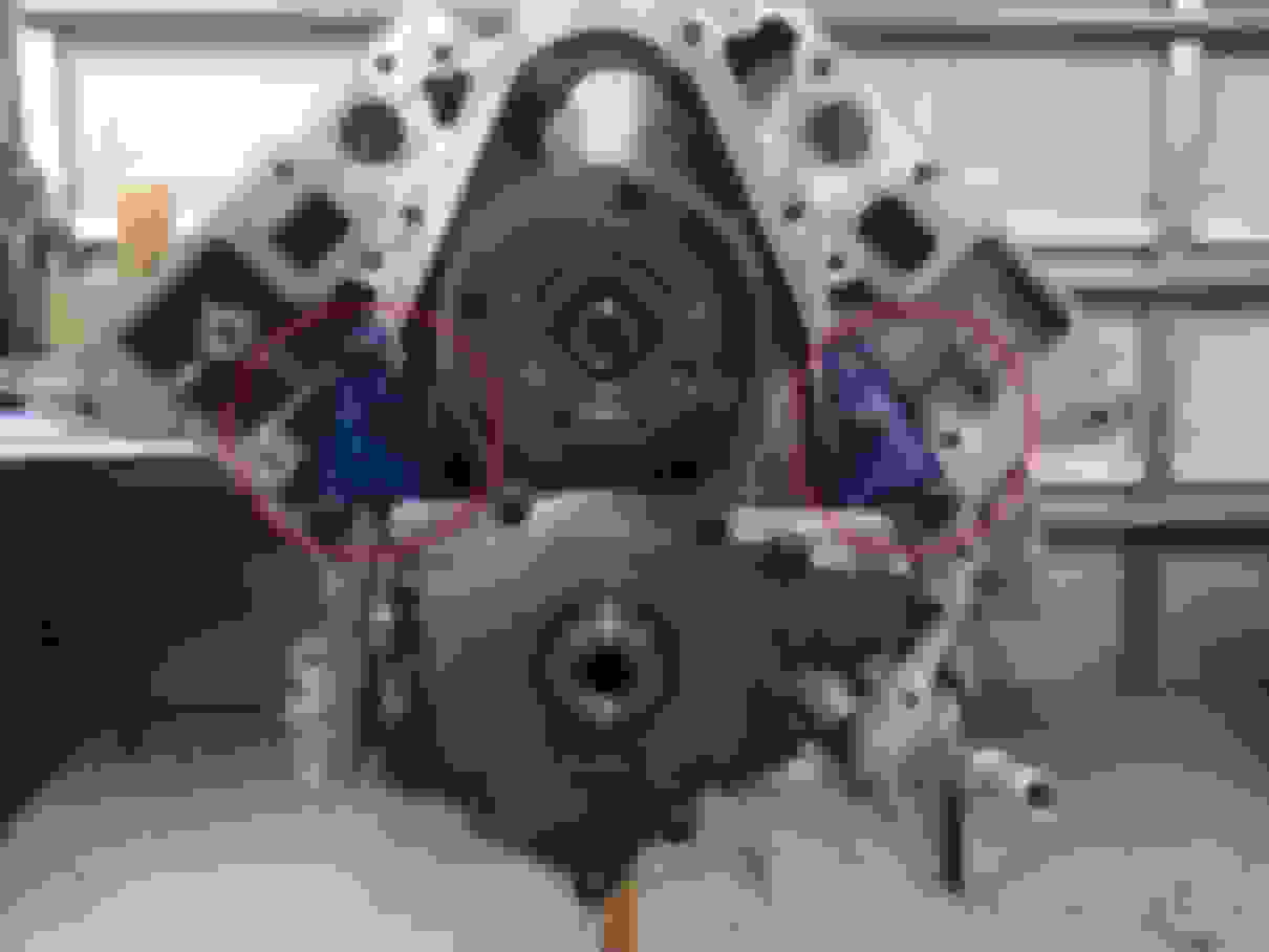
Next, we need to remove the oil pump, but before we do that, we MUST install these blue things! These blue things are the factory specialty oil pump alignment tools. These ensure that the oil pump is PERFECTLY aligned when you reinstall it. You may think, �Nah, I don�t need to do this..�. I can assure you, yes you do! There have been dozens of posts for C7 cam upgrades where the person has low oil pressure after doing the job and can�t figure out why, and this is typically the cause! If the oil pump is not aligned properly, it WILL cause low oil pressure!
Ok now that I have reamed you a new one to make sure you don�t skip that step, we can take off the oil pump by removing these four 13MM bolts shown below, ensuring to notate which bolt goes where.
After all bolts are off, take the oil pump off carefully, and place it on the table.
Now that the oil pumps off, we need to set the timing before removing any other parts. We want the engine at top dead center at this point. That means the #1 piston, (first piston on the right side when looking at the front of the engine as pictured above) is at its highest point, and also that the timing marks on the gears are pointing to each other like the below pic. We call this �dot to dot�.
If the top gear is pointing up when the bottom gear is also pointing up, then you need to turn the crank over one more whole turn as you are on the wrong engine stroke. Once they are both all lined up where the cam gear arrow is pointing straight down and the crank gear is pointing straight up, we are good to proceed.
Next, take off the bolt for the phaser (cam gear). This bolt is known as the Camshaft Position Actuator Solenoid Valve (CMP). This bolt MUST be replaced once it is removed, and you should have received one if you got a full cam kit. Be careful when removing this bolt, as the phaser will barely be suspended on there!
Once this bolt is removed, carefully remove the phaser (cam gear), along with the timing chain, and the gear that goes around the crank, and put all of these items on the table.
Now that all the timing stuff is out of the way, remove these four Torx bolts shown above, and remove the retainer plate for the cam.
With the retainer plate removed, VERY CAREFULLY remove the cam from the block.
Ok great! We are like half way there!!
Now is a good time to prepare your new lifters, so you�ll want to clean them with mineral spirits, then HAND dry them (do NOT blow dry with air and do not clean out the grease in them!)
Fill a clean bowl with fresh oil, after you have them mostly dry, and fully submerge them all.
�Cook 2 hours, stir, and continue cooking 2 additional hours. Careful, contents will be oiled when served �
Also, before you continue, you�ll need to upgrade some of the other components before we can begin re-assembly.
In addition to these things, the cylinder heads must have its components upgraded as well so that the valvetrain can keep up with the lift and demand from that new shiny cam. If you purchased ported cylinder heads from a company like Vengeance, they can port the heads, and then assemble your new dual springs, retainers, keepers, seals, and set valve height for you ahead of time.
I chose to have my cylinder heads ported by Texas Speed and Performance, and sent them my new valvetrain parts to install prior to shipping back so the disassembly and reassembly of the cylinder head valvetrain I will not be going over in detail.
All right, I’ll assume that at this point you have installed your cam phaser limiter, and performed your rocker arm trunnion upgrade. I’ll also assume your cylinder head valvetrain is upgraded and ready to go in both heads.
Now we will need to install the DoD delete kit. The Vengeance Racing DoD delete kit is simply a small aluminum plug kit that plugs the DoD/AFM oil galley towers to prevent oil from making its way up into the AFM hardware on the bottom side of the valley cover.
These plugs are soft aluminum so you simply need to hammer them into the holes for the AFM towers. I would recommend after getting the plug started in the hole, use a rag between the plug and the hammer to prevent marring up the top of the plugs. This is important later on to ensure the valley cover fits back on properly.
Once these are installed, now is a good time to clean out your bolt holes in the block and the thread of your bolts for the heads, timing cover, oil pan, etc. In the case of the head bolts, we will replace those with studs next so no worries about those. If you are in a pinch to find a proper thread chaser for the cylinder head bolt holes, you can actually take one of the old bolts, and use a cutoff wheel to carve a few cuts into the bolt long ways to make it simulate a thread tap. It works great actually.
Cleaning out the bolt holes is required as there will be old RTV sealants, and threadlocker present that will interfere with reassembly. Also you’ll need to make sure to clean off all the old RTV sealant from the mating surfaces of the block and parts we removed. Razor blades are your friend. I personally used an angle die grinder with a soft blue scuff pad but if you’ve never done that before don’t do it. You can easily take off too much material to cause an issue. You should use razor blades!
Once everything is all cleaned up, let’s install the new ARP head studs. Make sure you use the included ARP grease to grease up the threads on both ends of the studs. Install the studs by hand! Do not use a ratchet with an Allen bit! I chose to use some T-handle Allen wrenches to get the studs installed easier and evenly. Again, do not tighten the stud itself!
Once the head studs are all installed, we are ready to start greasing up our cam. Grease all contact points as I have done in the below picture. For this step, I prefer to use Redline Cam Paste, as it’s thicker than competitors engine assembly lube and will stay put until engine is started up.
Ok, now go put on a Metallica shirt because this is going to get heavy VERY CAREFULLY slide the cam into the block.
Now that the cam is installed, we need to install the cam retainer plate. To do this, apply BLUEthread locker to the bolts, install them and torque to 11 lb. ft. in the sequence shown.
Once the cam retainer plate is installed, grab your cam phaser, your new C5R timing chain, and you crank timing gear. First, put the crank timing gear on the front of the crankshaft, then put the timing chain on it, then lastly put the phaser gear inside the chain, and slide it all back.
If you did it correctly, you should be able to get the phaser onto the cam guide seated, and the timing should line up like how we took it off. If the timing does not line up, remove, adjust, install until you get it right. Now install the new CMP Actuator bolt through the phaser, and hand tighten for now.
In order to properly tighten this bolt, which is a one-time use Torque To Yield (TTY) bolt, we need to torque it to 48 lb. ft. first, and then turn the bolt an additional 90 degrees. To do this, you will need a digital angle gauge. I use a Brownline Digital Angle Gauge for this as pictured below. It’s magnetic and sticks right to the torque wrench. After I get to 48 lb. ft., and set my gauge for 90 degrees, I can then turn it exactly 90 degrees farther so it is torqued properly.
Alright, that’s all set. Now let’s go ahead and install our new lifters! Go ahead and grab them from the bowl of oil you had them stewing in, and slide them into the block one at a time ensuring the “roller” side is down.
After getting these installed, you need to install the new lifter trays, ensuring that they mate up to the lifters so that the lifters sit inside the trays. This is so the lifters do not turn sideways in the block. After these are in, install the 10MM bolts, one for each tray, (four total) to hold the lifter trays in place, and torque to 106 lb. in. each.
Now we will go ahead and install the fuel pump lifter back into the block, and torque the 13MM bolt to 106 lb. in.
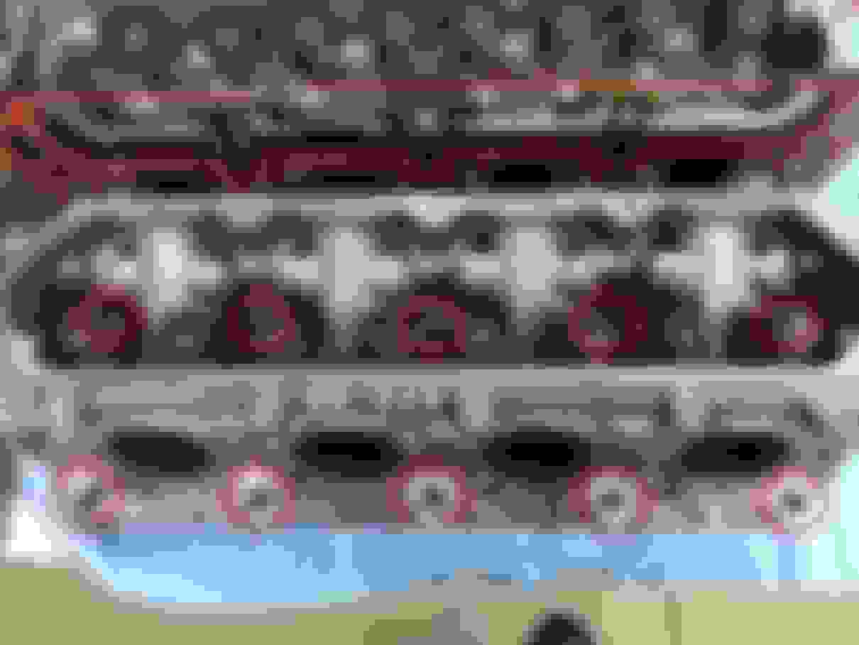
Let’s go ahead and put on our cylinder heads gaskets next:
Man that’s friggin’ gorgeous..
Now install your first cylinder head onto the block making sure you put it on the right side. Install the ARP nuts onto the studs, and torque these down in three equal phases using the below sequence to 115 lb. ft. This means do three passes, one complete pass at a time, to approx. 38 lb. ft., then to 76 lb. ft., then to 115 lb. ft. on the final pass.
Once this is completed, repeat the process for the other cylinder head.
Now that you’ve made it this far, it’s a great idea to consider “degreeing” your new cam. Doing this ensures that the cam “grind” you have is the same as what is on your cam card. If it’s off by 5-10 degrees and you didn’t degree the cam to figure this out, you could be chasing that problem extensively trying to figure it out later when the engine is assembled!
After both Cylinder heads are installed, you’re ready to tackle the oil pump. Grab your oil pump, and put it back on the front of the engine and finger screw in the bolts leaving them a pinch loose. Now you will need to torque the bolts to 18 lb. ft. in the below sequence WHILE KEEPING PRESSURE ON THE OIL PUMP AGAINST THE OIL PUMP ALIGNMENT TOOLS THE ENTIRE TIME!
Once the oil pump has been installed and torqued, go ahead and remove the oil pump alignment tools, we’re done with them. Now it’s time to tackle the front timing cover. While it’s not required, I would recommend replacing the front main seal while you have the front cover off, it’s cheap!
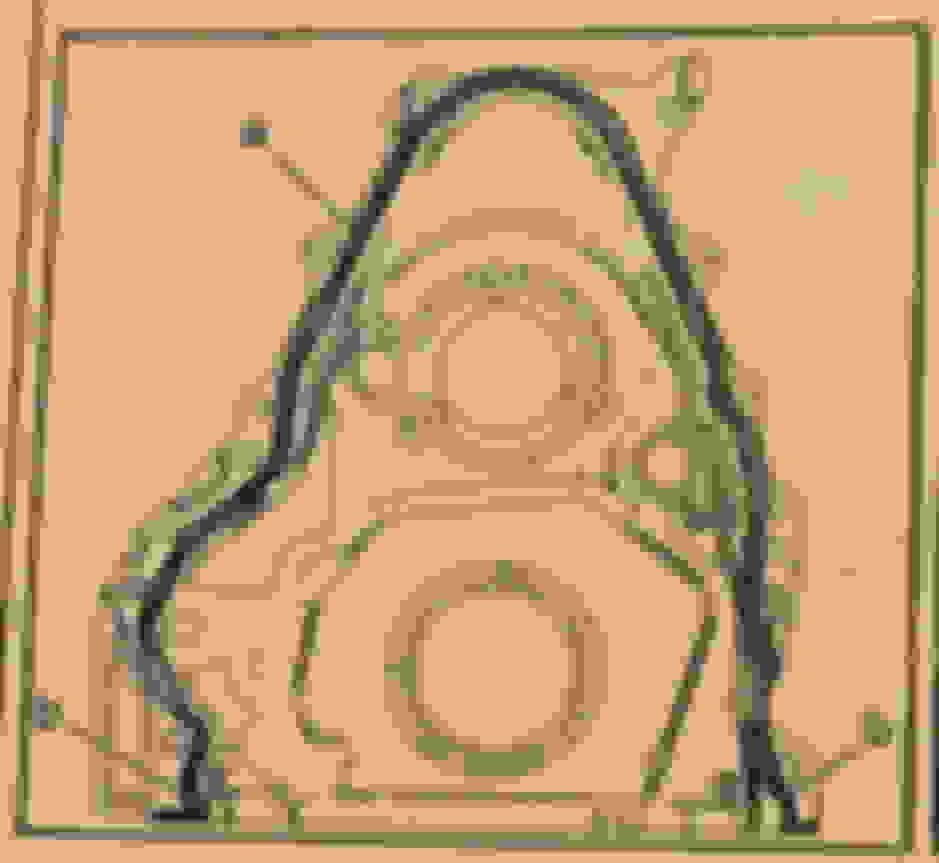
To install the RTV Sealant properly, you must follow the below diagram along with these instructions:
Apply a 3MM bead of RTV sealant to the area marked with a letter A, and apply a 5MM bead of RTV sealant to the area marked with the letter B. Install the cover and torque within 10 minutes of applying the bead!
Install the front cover onto the front of the engine, and finger screw all the bolts in evenly to draw the cover onto the block. Next, tighten them in sequence as shown below. For all numbers indicated by a “2 or 3” torque them to 18 lb. ft.
Once all bolts are torqued, make sure to reconnect the electrical connector to the oil pump on the underside of the engine!
Next is the oil pan. Install the oil pan as follows:
Apply a 3MM bead of RTV sealant to the area marked with a letter A, and apply a 5MM bead of RTV sealant to the area marked with the letter B. Install the cover and torque within 10 minutes of applying the bead!
Install all bolts for the oil pan finger tight and evenly to draw the oil pan on properly. Torque all bolts according to the below sequence.
NOTE: It was recently discovered that the torque values below may be accidentally reversed in the 2014 service manual. I am attempting to confirm this.
Per 2014 service manual:
13MM bolts (indicated in the below diagram with the number “2”) will be torqued to 106 lb. in. and all 10MM bolts (indicated in the below diagram with the number “3”) will be torqued to 18 lb. ft. No, you didn’t read that wrong, the smaller bolts have a higher torque.
Per current GM SI website (9/4/19) These values are reported to be:
13MM bolts (indicated in the below diagram with the number “2”) will be torqued to 18 lb. ft. and all 10MM bolts (indicated in the below diagram with the number “3”) will be torqued to 106 lb. in.
Alrighty, now we need to also torque the bolts for the oil cooler bracket. Torque the 13MM bolts to 18 lb. ft., and torque the 11MM bolts to 89 lb. in.
Next you need to install the valley cover, but before doing so, do you need to install a lash cap for the fuel pump?! If you are using a cam with a 32% fuel lobe, then yes, you do need a lash cap.
Follow this guide to perform the proper measurements and get the right lash cap installed:
After you get your lash cap installed, go ahead and install the valley cover on the top of the valley, you may need a few taps from a rubber mallet to get it to seat properly with the new DoD delete plugs on the top of the block. They will sit inside some recessed areas in the bottom of the valley cover. Once the valley cover is sitting correctly, go ahead and install the bolts and torque them down a first pass to 106 lb. in., and then a final pass of 18 lb. ft. using the below sequence:
Now that the Valley cover it back on, we're going to move on to the final steps before we are ready to reinstall the motor. The last things to do are to install the pushrods and the rocker arms.
The pushrods are pretty straightforward. Install them one at a time, and ensure that they seat into the middle of the lifter properly.
Now go ahead and install the rocker arms and bolts finger tight for all valves. If you had your heads ported, then there is a good chance that the intake runners will have "holes" in them where the porting exposed the bottom of the rocker arm bolt holes. No problem if this is the case, you simply need to install the rocker arm bolts with thread SEALANT on them, NOT THREADLOCKER!
Ensure that the pushrods seat themselves alllll the way into the rocker arm properly. a good test is to use your fingers to twist the pushrod to ensure it rotates freely and is not binding on anything.
The rocker arms have a "net build" valve lash. This means they are not adjustable, but they MUST be torqued down in a specific order when the lifters are "off-lobe".
1. Ensure that the engine is at top dead center of the compression stroke. (if you have not rotated the crankshaft, then you are still at TDC at this point, "dot-to-dot"). In this position, Cylinder 1 will be "off-lobe" on base of circle, and the crankshaft sprocket key will be at the 1:30 position.
2. The engine firing order is 1, 8, 7, 2, 6, 5, 4, 3
Cylinders 1, 3, 5, 7 are left bank
Cylinders 2, 4, 6, 8 are right bank
3. Tighten the rocker arm bolts for the EXHAUST VALVES for 1, 2, 7, and 8 to 22 lb. ft.
4. Tighten the rocker arm bolts for the INTAKE VALVES for 1, 3, 4, and 5 to 22 lb. ft.
5. Rotate the crankshaft 360 degrees.
6. Tighten the rocker arm bolts for the EXHAUST VALVES for 3, 4, 5, and 6 to 22 lb. ft.
7. Tighten the rocker arm bolts for the INTAKE VALVES for 2, 6, 7, and 8 to 22 lb. ft.
Check, check, and check again to ensure you didn't miss any!!
Go ahead and reinstall your crank pulley now. If you are using an OEM crank pulley, then use your old crank pulley bolt to "draw on" the crank pulley. Then remove it and use your new crank pulley bolt and torque to spec using RED threadlocker on the threads. If you have an innovators west pulley, then you should have a longer bolt to use for drawing on the crank pulley, and then a shorter bolt for final installation.
Now its time to put the engine back in the car! I would recommend using some painters tape to mask off the intake and exhaust ports, and use small cutout sections of a black garbage bag taped over the heads to protect from dirt getting in there during the reinstall. Follow the guide I mentioned at the beginning of this guide in the reverse order to get the engine installed.
One thing I will mention regarding the reassembly of the fuel system is that the gasket for the HPFP, the bolts for the HPFP, and both of the fuel hardlines that bolt to the top of the valley are all one time use and must be replaced when reassembling! When reinstalling the fuel rails, technically you are support to replace the injector seals, but I never replaced mine as they were in good shape and I did not have a problem.
Hope this guide helps! Next How To guide will be doing Vengeance Racing drop in LT1 pistons! Stay tuned!
All right, I’ll assume that at this point you have installed your cam phaser limiter, and performed your rocker arm trunnion upgrade. I’ll also assume your cylinder head valvetrain is upgraded and ready to go in both heads.
Now we will need to install the DoD delete kit. The Vengeance Racing DoD delete kit is simply a small aluminum plug kit that plugs the DoD/AFM oil galley towers to prevent oil from making its way up into the AFM hardware on the bottom side of the valley cover.
These plugs are soft aluminum so you simply need to hammer them into the holes for the AFM towers. I would recommend after getting the plug started in the hole, use a rag between the plug and the hammer to prevent marring up the top of the plugs. This is important later on to ensure the valley cover fits back on properly.
Once these are installed, now is a good time to clean out your bolt holes in the block and the thread of your bolts for the heads, timing cover, oil pan, etc. In the case of the head bolts, we will replace those with studs next so no worries about those. If you are in a pinch to find a proper thread chaser for the cylinder head bolt holes, you can actually take one of the old bolts, and use a cutoff wheel to carve a few cuts into the bolt long ways to make it simulate a thread tap. It works great actually.
Cleaning out the bolt holes is required as there will be old RTV sealants, and threadlocker present that will interfere with reassembly. Also you’ll need to make sure to clean off all the old RTV sealant from the mating surfaces of the block and parts we removed. Razor blades are your friend. I personally used an angle die grinder with a soft blue scuff pad but if you’ve never done that before don’t do it. You can easily take off too much material to cause an issue. You should use razor blades!
Once everything is all cleaned up, let’s install the new ARP head studs. Make sure you use the included ARP grease to grease up the threads on both ends of the studs. Install the studs by hand! Do not use a ratchet with an Allen bit! I chose to use some T-handle Allen wrenches to get the studs installed easier and evenly. Again, do not tighten the stud itself!
Once the head studs are all installed, we are ready to start greasing up our cam. Grease all contact points as I have done in the below picture. For this step, I prefer to use Redline Cam Paste, as it’s thicker than competitors engine assembly lube and will stay put until engine is started up.
Ok, now go put on a Metallica shirt because this is going to get heavy VERY CAREFULLY slide the cam into the block.
Now that the cam is installed, we need to install the cam retainer plate. To do this, apply BLUEthread locker to the bolts, install them and torque to 11 lb. ft. in the sequence shown.
Once the cam retainer plate is installed, grab your cam phaser, your new C5R timing chain, and you crank timing gear. First, put the crank timing gear on the front of the crankshaft, then put the timing chain on it, then lastly put the phaser gear inside the chain, and slide it all back.
If you did it correctly, you should be able to get the phaser onto the cam guide seated, and the timing should line up like how we took it off. If the timing does not line up, remove, adjust, install until you get it right. Now install the new CMP Actuator bolt through the phaser, and hand tighten for now.
In order to properly tighten this bolt, which is a one-time use Torque To Yield (TTY) bolt, we need to torque it to 48 lb. ft. first, and then turn the bolt an additional 90 degrees. To do this, you will need a digital angle gauge. I use a Brownline Digital Angle Gauge for this as pictured below. It’s magnetic and sticks right to the torque wrench. After I get to 48 lb. ft., and set my gauge for 90 degrees, I can then turn it exactly 90 degrees farther so it is torqued properly.
Alright, that’s all set. Now let’s go ahead and install our new lifters! Go ahead and grab them from the bowl of oil you had them stewing in, and slide them into the block one at a time ensuring the “roller” side is down.
After getting these installed, you need to install the new lifter trays, ensuring that they mate up to the lifters so that the lifters sit inside the trays. This is so the lifters do not turn sideways in the block. After these are in, install the 10MM bolts, one for each tray, (four total) to hold the lifter trays in place, and torque to 106 lb. in. each.
Now we will go ahead and install the fuel pump lifter back into the block, and torque the 13MM bolt to 106 lb. in.
Let’s go ahead and put on our cylinder heads gaskets next:
Man that’s friggin’ gorgeous..
Now install your first cylinder head onto the block making sure you put it on the right side. Install the ARP nuts onto the studs, and torque these down in three equal phases using the below sequence to 115 lb. ft. This means do three passes, one complete pass at a time, to approx. 38 lb. ft., then to 76 lb. ft., then to 115 lb. ft. on the final pass.
Once this is completed, repeat the process for the other cylinder head.
Now that you’ve made it this far, it’s a great idea to consider “degreeing” your new cam. Doing this ensures that the cam “grind” you have is the same as what is on your cam card. If it’s off by 5-10 degrees and you didn’t degree the cam to figure this out, you could be chasing that problem extensively trying to figure it out later when the engine is assembled!
After both Cylinder heads are installed, you’re ready to tackle the oil pump. Grab your oil pump, and put it back on the front of the engine and finger screw in the bolts leaving them a pinch loose. Now you will need to torque the bolts to 18 lb. ft. in the below sequence WHILE KEEPING PRESSURE ON THE OIL PUMP AGAINST THE OIL PUMP ALIGNMENT TOOLS THE ENTIRE TIME!
Once the oil pump has been installed and torqued, go ahead and remove the oil pump alignment tools, we’re done with them. Now it’s time to tackle the front timing cover. While it’s not required, I would recommend replacing the front main seal while you have the front cover off, it’s cheap!
To install the RTV Sealant properly, you must follow the below diagram along with these instructions:
Apply a 3MM bead of RTV sealant to the area marked with a letter A, and apply a 5MM bead of RTV sealant to the area marked with the letter B. Install the cover and torque within 10 minutes of applying the bead!
Install the front cover onto the front of the engine, and finger screw all the bolts in evenly to draw the cover onto the block. Next, tighten them in sequence as shown below. For all numbers indicated by a “2 or 3” torque them to 18 lb. ft.
Once all bolts are torqued, make sure to reconnect the electrical connector to the oil pump on the underside of the engine!
Next is the oil pan. Install the oil pan as follows:
Apply a 3MM bead of RTV sealant to the area marked with a letter A, and apply a 5MM bead of RTV sealant to the area marked with the letter B. Install the cover and torque within 10 minutes of applying the bead!
Install all bolts for the oil pan finger tight and evenly to draw the oil pan on properly. Torque all bolts according to the below sequence.
NOTE: It was recently discovered that the torque values below may be accidentally reversed in the 2014 service manual. I am attempting to confirm this.
Per 2014 service manual:
13MM bolts (indicated in the below diagram with the number “2”) will be torqued to 106 lb. in. and all 10MM bolts (indicated in the below diagram with the number “3”) will be torqued to 18 lb. ft. No, you didn’t read that wrong, the smaller bolts have a higher torque.
Per current GM SI website (9/4/19) These values are reported to be:
13MM bolts (indicated in the below diagram with the number “2”) will be torqued to 18 lb. ft. and all 10MM bolts (indicated in the below diagram with the number “3”) will be torqued to 106 lb. in.
Alrighty, now we need to also torque the bolts for the oil cooler bracket. Torque the 13MM bolts to 18 lb. ft., and torque the 11MM bolts to 89 lb. in.
Next you need to install the valley cover, but before doing so, do you need to install a lash cap for the fuel pump?! If you are using a cam with a 32% fuel lobe, then yes, you do need a lash cap.
Follow this guide to perform the proper measurements and get the right lash cap installed:
After you get your lash cap installed, go ahead and install the valley cover on the top of the valley, you may need a few taps from a rubber mallet to get it to seat properly with the new DoD delete plugs on the top of the block. They will sit inside some recessed areas in the bottom of the valley cover. Once the valley cover is sitting correctly, go ahead and install the bolts and torque them down a first pass to 106 lb. in., and then a final pass of 18 lb. ft. using the below sequence:
Now that the Valley cover it back on, we're going to move on to the final steps before we are ready to reinstall the motor. The last things to do are to install the pushrods and the rocker arms.
The pushrods are pretty straightforward. Install them one at a time, and ensure that they seat into the middle of the lifter properly.
Now go ahead and install the rocker arms and bolts finger tight for all valves. If you had your heads ported, then there is a good chance that the intake runners will have "holes" in them where the porting exposed the bottom of the rocker arm bolt holes. No problem if this is the case, you simply need to install the rocker arm bolts with thread SEALANT on them, NOT THREADLOCKER!
Ensure that the pushrods seat themselves alllll the way into the rocker arm properly. a good test is to use your fingers to twist the pushrod to ensure it rotates freely and is not binding on anything.
The rocker arms have a "net build" valve lash. This means they are not adjustable, but they MUST be torqued down in a specific order when the lifters are "off-lobe".
1. Ensure that the engine is at top dead center of the compression stroke. (if you have not rotated the crankshaft, then you are still at TDC at this point, "dot-to-dot"). In this position, Cylinder 1 will be "off-lobe" on base of circle, and the crankshaft sprocket key will be at the 1:30 position.
2. The engine firing order is 1, 8, 7, 2, 6, 5, 4, 3
Cylinders 1, 3, 5, 7 are left bank
Cylinders 2, 4, 6, 8 are right bank
3. Tighten the rocker arm bolts for the EXHAUST VALVES for 1, 2, 7, and 8 to 22 lb. ft.
4. Tighten the rocker arm bolts for the INTAKE VALVES for 1, 3, 4, and 5 to 22 lb. ft.
5. Rotate the crankshaft 360 degrees.
6. Tighten the rocker arm bolts for the EXHAUST VALVES for 3, 4, 5, and 6 to 22 lb. ft.
7. Tighten the rocker arm bolts for the INTAKE VALVES for 2, 6, 7, and 8 to 22 lb. ft.
Check, check, and check again to ensure you didn't miss any!!
Go ahead and reinstall your crank pulley now. If you are using an OEM crank pulley, then use your old crank pulley bolt to "draw on" the crank pulley. Then remove it and use your new crank pulley bolt and torque to spec using RED threadlocker on the threads. If you have an innovators west pulley, then you should have a longer bolt to use for drawing on the crank pulley, and then a shorter bolt for final installation.
Now its time to put the engine back in the car! I would recommend using some painters tape to mask off the intake and exhaust ports, and use small cutout sections of a black garbage bag taped over the heads to protect from dirt getting in there during the reinstall. Follow the guide I mentioned at the beginning of this guide in the reverse order to get the engine installed.
One thing I will mention regarding the reassembly of the fuel system is that the gasket for the HPFP, the bolts for the HPFP, and both of the fuel hardlines that bolt to the top of the valley are all one time use and must be replaced when reassembling! When reinstalling the fuel rails, technically you are support to replace the injector seals, but I never replaced mine as they were in good shape and I did not have a problem.
Hope this guide helps! Next How To guide will be doing Vengeance Racing drop in LT1 pistons! Stay tuned!
Again buddy great job on your work with great step by step DIY.
Thanks!
Originally Posted by ajrothm
This is one of the best write ups I have seen on this forum for a cam install in 11 years here.
Very nice job and thanks for your effort! Keep us posted on the numbers!
Thanks for the kind words
I try to do a lot of guides like this to help the community as much as I can. Trying to fill the shoes of Theta since he's hasn't been around . Miss that guy..
FYREANT does great job on his HOW TOs... We need more people like him
I wanted to add one thing... If you are not getting your heads CNCed or changing heads or upgrading your fuel injectors... You don't have to take your Fuel Injectors out... Just leave the injectors in and fuel rail attached to them...
May i ask how you cleaned the pistons, head deck and exhaust ports?
thx
I didn't. I replaced the pistons with forged ones, and had the heads ported by Texas Speed and Performance. They cleaned the heads and planed the deck as part of the process.
I didn't. I replaced the pistons with forged ones, and had the heads ported by Texas Speed and Performance. They cleaned the heads and planed the deck as part of the process.
Ant
Here is a link for the Oil Pump housing alignment tool.
@ $125 its a little pricy
Could I scribe the alignment on a template using the bolt holes as a work around? or is this absolutely the way to go.
Here is a link for the Oil Pump housing alignment tool.
@ $125 its a little pricy
Could I scribe the alignment on a template using the bolt holes as a work around? or is this absolutely the way to go.
Good luck with that site. I ordered for them and after three weeks of not getting a tracking number and no package demanded a refund. Could you "make" one? Probably. But you need a real one to copy first. Personally I'd keep an eye on ebay. Thats where I got mine..
Great job I cant tell you how much i like your threads, pics, and descriptions are great and show what I like to see. and I use to write instructions for a living ha.
One question. On the oil pump. how can the oil pump be miss alighned? its bolted on using bolt holes, you cant spin it and mount it wrong? I see how to use the alignment things but how can you do it wrong some more info would be good to have in my head.
Thank you, I appreciate it. I try to help the community as much as I can!
The bolt holes that go through the oil pump have some play in them, and heres the big reveal.. the gear inside the middle of the pump (that the crank goes through, has all kinds of play. Look up the inside of an LS oil pump and you will see what I mean. All those things combined and the pump can certainly get misaligned.

 07-08-2017, 11:22 AM


 VERY CAREFULLY slide the cam into the block.


 . Miss that guy..


