When you click on links to various merchants on this site and make a purchase, this can result in this site earning a commission. Affiliate programs and affiliations include, but are not limited to, the eBay Partner Network.
HOW TO: Install a Mantic Twin Disc Clutch and Flywheel in your C7
NOTE: This How-To guide is neither endorsed by or property of Corvette Forum or myself in any way/shape/form. All liability stemming from any actions taken in relation to this guide is solely placed upon the end user. (This means you!)
Part 1
So you�ve pulled the motor to put a cam in or some forged pistons and you�re thinking �while I have it out, lets upgrade the clutch too..� Here�s the guide to follow! It�s a good idea to lay your parts out and make sure you aren�t missing anything before you start:
Make sure you remove these small Styrofoam pieces now, so you don�t forget to do so later!
If you haven�t already pulled the motor, you�ll need to do that first, or remove the torque-tube to get access to the clutch and flywheel.
Assuming you haven�t pulled the motor yet, I�ve already written a guide on how to get it out, which you can find here. Come back here after you are done with that guide...
Also, you�re going to need a flywheel holder tool for this, so I�d recommend picking one up off of eBay:
Once the motor is out, go ahead and remove the old clutch pressure plate bolts located in the red circles below.
Next, remove the clutch disc (simply grab it by the middle splines and pull it out)
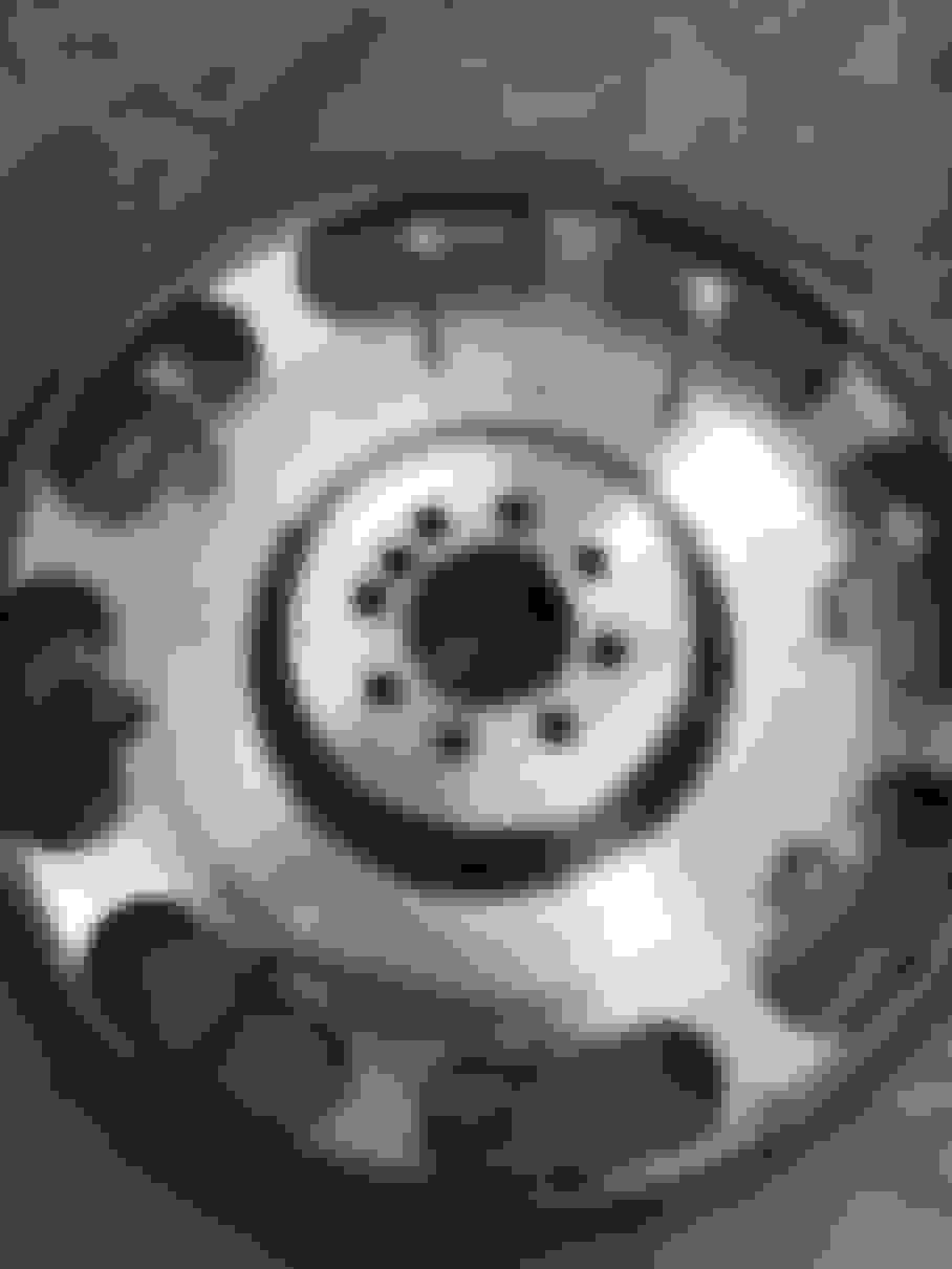
Now we need to take off the flywheel. Remove the eight 15MM 12-point bolts, and then remove the flywheel from the end of the crank.
Next lets go over removing the clutch release bearing (also known as the throw-out bearing)
First remove the throw-out bearing itself:
Then, if you still see a black rubber piece around the plastic, remove that too. You want it to look like this when you are done:
Next lets install the new throw-out bearing and spacer that came with our kit. First, put a little bit of Vaseline onto the white plastic part of the concentric slave cylinder, and also on the O-rings that are in the throw-out bearing spacer.
The spacer is particularly tricky to install as it has two small O-rings inside of it. Size is 2MM C.S. (Cross section) x 38MM I.D. (42MM O.D) in case you damage them and need to find them in a pinch. The tricky part is getting this spacer on there without ripping the O-rings to shreds like I did!
Here�s the trick.. well, how I did it. I took one of those gold letter sized envelopes (because its thicker than paper, but not as thick as cardboard) and cut a rectangular section out about 2� x 4�. I then wrapped it around the white plastic section of the concentric slave cylinder, and then tucked the protruding part of the paper inside the throw-out bearing spacer. Then I simply wiggled it on there very slowly.
Doing it this way provides a smooth path for the O-rings to travel without them having anything to bind up against. After its done, you�ll need to wiggle the spacer a bit to get the paper out, and then you�re all set. Don�t worry, the spacer is not supposed to sit on there �tight�. If you wiggle it, it will wiggle. Don�t try to pull if off as it could pull of easily and you�d have to go through that again.. lol.
Once you have the spacer on there, now you can install the throw-out bearing itself onto the spacer and you�re all set in the engine bay at this point.
While we are replacing the clutch and flywheel, we�re going to go over replacement of the input shaft pilot bearing as pictured below:
To remove it, you�ll need to use a bearing puller as shown in the two pictures below to get it out:
This set is from Harbor Freight Tools and comes with four size collets, which I used the 9/16� to 11/16� (not smallest one but second smallest one) as the smallest one would not get large enough to grab the bearing properly. I did have to sand down the edges of the collet tip so it would fit into the bearing hole, but it was not much at all as I did it with plumbers cloth (180 grit).
After you get it in there, expand it out as large as it will go until it gets tight. Now you�re ready to start slamming the slide hammer back until it walks it out.
Once that�s out, we will need to install the new one. It�s already pre-greased inside, so no need to worry about that. To install it, I actually used a harmonic balancer tool which you can also get from Harbor Freight Tools. Below you can see how it needs to be setup. I used a thick square of solid steel where my yellow arrow is so that the tip of the puller bolt would be able to press against the entire bearing to push it in.
You do NOT want to use the centerpoint to push the inner section of the bearing!! This will put too much stress on the ball bearings and cause pre-mature failure! I would also recommend removing the pointy tip from the centerpoint so you don�t damage it anyway. Push the bearing in until the outer ring of the bearing is flush with the outer edge of the bearing race.
NOTE: I won�t go over it in this guide, but if you�re already at this point it would be a good idea to replace the rear main seal, and the �engine block plug� (oil filter diverter valve).
Once you’re all down with the pilot bearing, we can turn our focus to the flywheel. Be sure to clean the flywheel with brake cleaner first and wipe it down good before going further. Also, before we put the new one on, I’d recommend chasing the threads with a tap, and if you don’t have one that size you can use one of the old flywheel bolts to do it. Simply use a pneumatic cutoff wheel to grind some vertical lines in the bolt and you essentially have a tap now that is the perfect size.
Once the threads a cleaned out, go ahead and bring your new shiny flywheel over. First we need to install the long bolts that they give us from the back side of the flywheel like this:
Now go ahead and stand the flywheel up, and push the bolts through so the heads seat into the recessed channel in the back of the flywheel. They will be used to hold the bolts indefinitely while we tighten nuts onto them later on. With all the bolts pulled through, you are cleared to mount the flywheel on the crank as shown below. Before you do that, read this so you know what you are getting into. The flywheel bolts require that you use RED Threadlocker!
Also, these new bolts (the ones included with the Mantic clutch kit) have a shallow head on them, so you need to make sure you have a socket that grips them REALLY well or you will round these things off before you get them tightened properly! Additionally, these bolts require you to toque them to in three complete passes using the sequence shown below. The third pass requires you to torque the bolts to a specific angle, so you will need a digital angle gauge to complete this. I personally use a Brownline Digital Angle Gauge but you can use any one that works. After applying the RED threadlocker, go ahead and finger screw these bolts in.
• First pass torque bolts 1-8 to 11 lb. ft.
• Second pass torque bolts 1-8 to 22 lb. ft.
• Third pass torque bolts 1-8 to an additional 45 DEGREES.
(Should you choose to go with ARP flywheel bolts, the part number for them are as follows: For LT1 and LT4: 234-2801. I called ARP and they advised that the LT4 used 234-2802, however, when I look up both part numbers in their catalog its conflicting information (shown below). I measured mine (LT1) and 234-2801 was indeed correct for my application. I would recommend you confirm your own specifics before ordering. My best guess is that the second line item is for the 6.2L trucks.)
Fantastic. Now that the flywheel is installed, we can move on to the next part, installing the drive blocks. Slide the drive blocks onto the bolts all the way, and use your finger from the back side to ensure the head of the bolts do not work their way out of the recessed channel in the flywheel.
Now we need to locate the correct clutch disc to install first, since there are two. Locate the clutch disc that says “FLYWHEEL SIDE” on it as shown below:
We are going to install it so that, you guessed it, the flywheel side of the disc will touch the flywheel!
Go ahead and put it on there, and then insert the clutch alignment tool (black thing with splines like the input shaft) into clutch disc so that the tip of the tool enters the center of the pilot bearing. It should sit up on its own and hold the clutch disc perfectly centered now.
Now we need to install the “intermediate plate” onto the drive blocks as shown below. BE CAREFUL with the little springs on the intermediate plate! They are specially set from the factory for release. Also, make sure the heads of the bolts are still in the channel on the back of the flywheel.
Now grab the other clutch disc, and locate the writing on it that says "PRESS PLT SIDE" just like the image below, and install it so that its facing out at you just like the picture. NOTE: You will need to temporarily remove the clutch alignment tool to get the second disc on, then reinsert it, all the way into the pilot bearing again.
With the second clutch disc installed, we need to put on the first part of the pressure plate cover assembly. Grab the last "silver piece" you have left, and install it with the smooth raised part facing out as shown in the following two pictures:
Now grab your anodized red pressure plate cover and install it onto the bolts. After this is on, install the lock washers so that they have the rounded face facing outwards like the image below:
Start installing the nuts onto the bolts and while doing so again make sure that the head of the bolts are still in the recessed area in the back of the flywheel. Hold your finger back there if you need to until you get the threads started. I chose to use some blue threadlocker on these bolts just to be safe, though its not mandatory.
Now go ahead and evenly start tightening the nuts down to draw the pressure plate cover onto all the way no more than � turn for each nut at a time always going across diagonally to the bolts on the adjacent side. During this process you need to make 100% sure that the driver blocks DO NOT BIND UP on the small machined step on the flywheel or the small machined step on the pressure plate cover!
Follow the sequence shown in the below image to tighten the bolts for the pressure plate to a torque spec of 33Nm (24.34 lb. ft.) I just tightened them to 25 lb. ft. personally.
If the components are installed correctly, the fingers on the pressure plate the fingers on the diaphram should be even and level with the cover.
That’s it! You’re ready to put the engine back in the car! Pedal feel should be about the same as factory, though the clutch with definitely have a noticable “chatter” when starting to take off from a stop in first gear, this is normal.
Si I may have a wearing and possibly failing clutch at some point in the near future, is this something that would be more durable and longer lasting than the OEM clutch? My concern is I dont want to replace the OEM one and then turn around and have to replace it again in 2-3 years. I don't track it either.
Si I may have a wearing and possibly failing clutch at some point in the near future, is this something that would be more durable and longer lasting than the OEM clutch? My concern is I dont want to replace the OEM one and then turn around and have to replace it again in 2-3 years. I don't track it either.
Yes. This clutch can hold up to 1010 FT. LBs. at the flywheel and feels pretty much stock.
Great write up. I was going to go with the Mantic twin clutch but decided just to go with the Katech light flywheel. There is about a 25 lb weight reduction. How noticeable is the difference in engine spin up or down with the lighter clutch?
Great write up. I was going to go with the Mantic twin clutch but decided just to go with the Katech light flywheel. There is about a 25 lb weight reduction. How noticeable is the difference in engine spin up or down with the lighter clutch?
That engine spin up is almost all related to the flywheel weight reduction. So I can�t answer your question really. Nobody replaces the clutch for weight, just for more grip related to power upgrades.
Great write up. I was going to go with the Mantic twin clutch but decided just to go with the Katech light flywheel. There is about a 25 lb weight reduction. How noticeable is the difference in engine spin up or down with the lighter clutch?
if you dropped 25 lbs on the rotational mass of the clutch/flywheel assembly, engine spin up will be noticeable. Not that the stock setup is sluggish to begin with, it revs up pretty easily and quickly, but you will notice a difference. You'll also notice a difference when pulling away from a dead stop since you don't have as much rotational mass already in motion as you let the clutch out. It'll take more revs to get the car moving than before.
I actually just upgraded to a stage 3 Mantic, so sometime this week I'm probably going to update this guide to include the stage 3 steps.
Have you driven the car yet with the stage 3 Mantic? Mine is getting upgraded to the triple in March. Just curious if it feels different from the twin.
Have you driven the car yet with the stage 3 Mantic? Mine is getting upgraded to the triple in March. Just curious if it feels different from the twin.
not yet. I had the motor in the car the other day but the brand new slave decided to start leaking so I pulled the motor out again. New slave will be here Friday or Saturday.
Have you driven the car yet with the stage 3 Mantic? Mine is getting upgraded to the triple in March. Just curious if it feels different from the twin.
I had a twin and then went to a triple. Pedal feels the same because it's the same pressure plate. The only difference is the triple chatters a bit more. Overall I love it.
For those that wanted to know, the Tick Performance C6/C7 remote speed bleeder fits perfectly. Its their C6 version but also works on the C7..
I know this is an old thread Ant but do you think the speed bleeder could be installed with the engine and clutch still in the car. Their web site says no. Thanks.
I know this is an old thread Ant but do you think the speed bleeder could be installed with the engine and clutch still in the car. Their web site says no. Thanks.
Well, put it this way, I did it, but it was a major challenge. There�s simply no room to get your hand in there unfortunately. I would recommend you do it while things are apart for sure.

 07-10-2017, 02:03 AM