When you click on links to various merchants on this site and make a purchase, this can result in this site earning a commission. Affiliate programs and affiliations include, but are not limited to, the eBay Partner Network.
Tracy Lewis/RX Catch can/Elite Engineering R2-X Install on 2017+ grand sport
Okay guys so I got this kit from Tracy Lewis but I think I got the Z06 kit, as another thread recognized the parts. I am having a hard time finding updated instructions online; I feel like between all 3 of the companies that represent this catch can and clean side seperator, I can sort of cobble together a set of instructions that work for the newer pcv routing. Has anyone done this install yet on a 17 GS with this catchcan system?
On the updated PCV, is it still necessary to run a clean side separator? It sounds like on the LT1, it is. Not so much on the z06.
So from what I have found on Elite's 2015 stingray instructions, on the clean side, you T off of the two passenger side head valves and run that into the dry sump. You take the line (which is running to the intake filtered air) that was running to the dry sump and you plug that into the clean side separator. Is that correct?
17 Grand Sport PCV routing
.
Parts received:
Tracy Lewis Signature Series parts (looks like z06 kit)
I hope he is better now then when he came out with the can's in the c5 cars & knows what he is doing. I know the MMS catch can's work good.. Robert
Haha, Well I've sent them a message asking how, if not I guess I could return and go to MM. I wanted to give it a chance though since it seems like a good product.
Subie can you give me more detail? Which car do you have? I have heard the z06 doesn't really need it, but maybe the lt1, which I have, does.
If it's a 17 plus grand sport I'd love to see how you routed everything? I think I'm missing clamps for the T on the clean side.
The Tracy Lewis one had zero instructions, with a piece of paper pointing to the website. No updated instructions for newer years with the updated pcv layout. I'm not a mechanic for a living so this sort of thing slows me down, because I want to be positive I'm doing it right.
We did in fact send you the Z06 system. Our apologies. We can send the parts needed to install what you have.
Here is the link to all instructions. As we make these for hundreds of applications to included printed instructions for all would require us to raise prices to cover this so we are doing videos as well as downloadable PDF's on the site: https://rxcatchcans.com/chevy
I hope he is better now then when he came out with the can's in the c5 cars & knows what he is doing. I know the MMS catch can's work good.. Robert
Challenge anyone to take the Catchcan Challenge against that can. That traps less than 50% vs the 95% of this patented design. Here is how the test is conducted:
If your goal is to stop all oil ingestion, why would anyone want to allow half the oil and other contaminates still be ingested? Also, we provide full time evacuation instead of allowing pressure to build and vent. Can't understand why anyone would use such antiquated technologies from the pre mid 1960's. NO form of Professional racing "vents" due to the loss of power, increased wear and damage caused over time aside from Top Fuel and Top Alcohol that push all oil from the crankcase in one single run and require complete rebuilds every pass. From Indy cars to Professional drag racing, ALL pull full time evacuation and none vent.
Here is a sample of a recent message from a road racer that has fought with oil ingestion issues for over a year:
" I had the oil consumption and smoke problem at the track only. We discussed the routing of the lines a few weeks ago. We made the changes and now have both valve cover lines going direct into the oil tank.
I ran last week at WGI. The smoking is gone and the oil consumption is minimal !!!! Soon we will pull the SC cover to make sure its still clean under there. Thanks for the help getting is right.
We did in fact send you the Z06 system. Our apologies. We can send the parts needed to install what you have.
Here is the link to all instructions. As we make these for hundreds of applications to included printed instructions for all would require us to raise prices to cover this so we are doing videos as well as downloadable PDF's on the site: https://rxcatchcans.com/chevy
Tracy, these videos and instructions don't work now that the routes are different for the pcv on 2017 plus grand sport and probably stingray. I have a diagram I've posted in another thread and emailed you, can you have a look?
We need updated instructions. I think elite has them, sort of.
Can you take a look at the diagram above? The video has you do the wrong things now. You can't route the clean seperator to the driver valve cover now and I believe you need a T to the passenger valve cover barbs
Can you take a look at the diagram above? The video has you do the wrong things now. You can't route the clean seperator to the driver valve cover now and I believe you need a T to the passenger valve cover barbs
Sure will. Excellent! Wish you were closer, would do installation free and video for others.
Sure will. Excellent! Wish you were closer, would do installation free and video for others.
Will get you a reply tomorrow.
Thanks!!
Hah! Would be glad to. I'll upload pics of the install. I'm hoping subie or somone with a 17 can upload some install pics including the clean side seperator.
This new pcv routing, do the new vettes even need the clean side separator or did gm put one in the dry sump?
The driver side valve cover runs to that little tank on the dry sump which I assume is fresh air
Does anyone know if the clean side seperator is even needed on the new 17+ Grand sport/z51 setups? Edit: Talked to Tracy, you still do, they see even the updated models burping a little oil back up.
Does anyone know if the clean side seperator is even needed on the new 17+ Grand sport/z51 setups? Edit: Talked to Tracy, you still do, they see even the updated models burping a little oil back up.
Take the front most line from the sump tank and snap it on the CSS barb (should be a barb machined to accommodate that factory quick disconnect).
Then run a hose from that barb left open on the oil sump tank to a T you install into the line that connects to the passenger side valve cover front. (VC2 in your diagram). This now adds app. 3" in vertical height and the internal coalescing chamber to prevent any of that oil from burping into the main air intake. We still need that pathway though to release any pockets in the tank but now it will now release into the valve cover. Even though they come from the same tank, they are different circuits within the tank.
Center of the can run a hose direct to the valley barb that protrudes from the valley cover towards the driverside of the engine compartment underneath the throttle body. NO checkvalve in this line.
One outer fitting line with checkvalve flowing away from the can will connect to the intake manifold vacuum port located on the driverside of the IM snout, just behind the throttle body mount flange. This provides the evacuation suction when at idle, light cruise, or deceleration.
The opposite outer fitting on can with checkvalve inline flowing away from the can will connect to a barb you insert into the flexible coupler that attaches the main intake air tube to the throttle body. This provides the suction needed for continued evacuation when accelerating or at WOT when it is needed most. Now, this suction is NOT generated by the restriction of the air filter! This is generated via the Venturi Effect from the air flow past the end of that barb you add. And this is where the factory PCV system, and any "breathered" or "Vented" can falls far short as they both allow pressure to build when you least want it. All of these new engines come with low tension piston rings, and this is when "ring flutter" occurs. That is when the piston rings enter into a state of rapid vibration and increased blow-by is the immediate result, and wear is the long term result. This is why we never ignore the most important time when you need vacuum evacuation, at high loads/high RPM's when all other provide NO evacuation. Low tension piston rings must have suction below and pressure above them to maintain stability and seal properly.
The same mounting brackets are used on yours and the Z06.
So were sending the fittings you may need today, but the pictures of what you received appear to be all you need. I'll look closer and verify.
So to summarize, the filtered fresh MAF metered air enters from the main intake air tube assembly, and enters the dry sump tank. We simply move this point of entry to the billet CSS so it has both vertical height as well as the internal separation chamber that will contain most any oil that normally would burp backwards and enter the intake air tract upstream of the throttle body. From there this fresh air passes through the oil tank and one circuit through the cyclonic separator and all run to the valve covers. from there it is drawn past the rocker arms, down the oil returns, and into the main portion of the crankcase. All the while flushing and making up for the foul/dirty contaminant laden vapors that are being evacuated (sucked out) the valley cover. Into the main catchcan that separates app. 95% of the water, acids, oil mist, and abrasive particulate matter from these vapors so only scrubbed clean air enters as the intake air charge. Pressure can NEVER build as the CSS acts as a emergency relief path in the event you have a breach in the piston/ring/cylinder wall seal. Otherwise this system emulates an actual vacuum pump system closer than any other solution on the market today.
Some tips:
Make SURE to heat the hard plastic line you cut on the passengers side valve cover when you are going to slide in the 5/16x5/16x3/8" T to connect to the oil sumps front most barb. If cold they can crack.
Okay guys so I got this kit from Tracy Lewis but I think I got the Z06 kit, as another thread recognized the parts. I am having a hard time finding updated instructions online; I feel like between all 3 of the companies that represent this catch can and clean side seperator, I can sort of cobble together a set of instructions that work for the newer pcv routing. Has anyone done this install yet on a 17 GS with this catchcan system?
On the updated PCV, is it still necessary to run a clean side separator? It sounds like on the LT1, it is. Not so much on the z06.
So from what I have found on Elite's 2015 stingray instructions, on the clean side, you T off of the two passenger side head valves and run that into the dry sump. You take the line (which is running to the intake filtered air) that was running to the dry sump and you plug that into the clean side separator. Is that correct?
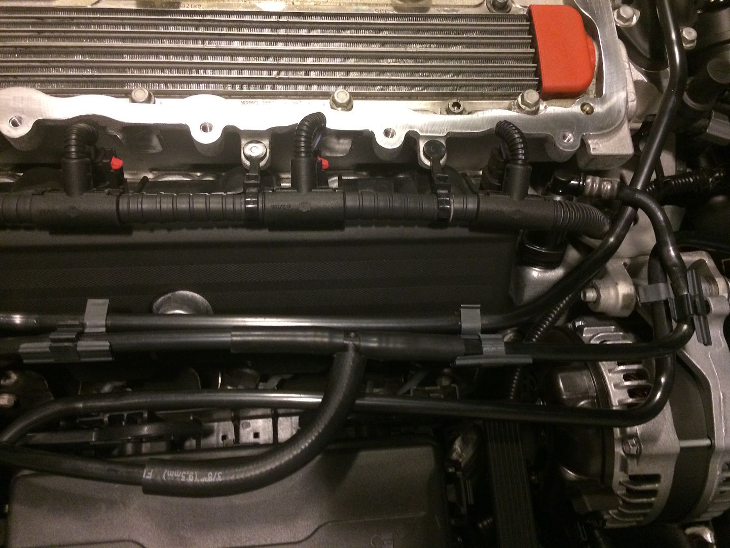
17 Grand Sport PCV routing
.
Parts received:
Tracy Lewis Signature Series parts (looks like z06 kit)
Looks like we sent a 3/8" T. Proper one going out today!!!
Looks like we sent a 3/8" T. Proper one going out today!!!
That 3/8" T would break the plastic ones? What size are those?
All: Here are the instructions from Tracy, hopefully if someone gets a catch can from him and has a grand sport or z51 with the new style pcv, this will help you do the install. Some of this conversation is custom to my situation since I got the z06 kit but have a grand sport, but I have enough parts to make it work (other than a smaller t connector, maybe).
Take the front most line from the sump tank and snap it on the CSS barb (should be a barb machined to accommodate that factory quick disconnect).
Then run a hose from that barb left open on the oil sump tank to a T you install into the line that connects to the passenger side valve cover front. (VC2 in your diagram). This now adds app. 3" in vertical height and the internal coalescing chamber to prevent any of that oil from burping into the main air intake. We still need that pathway though to release any pockets in the tank but now it will now release into the valve cover. Even though they come from the same tank, they are different circuits within the tank.
Center of the can run a hose direct to the valley barb that protrudes from the valley cover towards the driverside of the engine compartment underneath the throttle body. NO checkvalve in this line.
One outer fitting line with checkvalve flowing away from the can will connect to the intake manifold vacuum port located on the driverside of the IM snout, just behind the throttle body mount flange. This provides the evacuation suction when at idle, light cruise, or deceleration.
The opposite outer fitting on can with checkvalve inline flowing away from the can will connect to a barb you insert into the flexible coupler that attaches the main intake air tube to the throttle body. This provides the suction needed for continued evacuation when accelerating or at WOT when it is needed most. Now, this suction is NOT generated by the restriction of the air filter! This is generated via the Venturi Effect from the air flow past the end of that barb you add. And this is where the factory PCV system, and any "breathered" or "Vented" can falls far short as they both allow pressure to build when you least want it. All of these new engines come with low tension piston rings, and this is when "ring flutter" occurs. That is when the piston rings enter into a state of rapid vibration and increased blow-by is the immediate result, and wear is the long term result. This is why we never ignore the most important time when you need vacuum evacuation, at high loads/high RPM's when all other provide NO evacuation. Low tension piston rings must have suction below and pressure above them to maintain stability and seal properly.
The same mounting brackets are used on yours and the Z06.
So were sending the fittings you may need today, but the pictures of what you received appear to be all you need. I'll look closer and verify.
So to summarize, the filtered fresh MAF metered air enters from the main intake air tube assembly, and enters the dry sump tank. We simply move this point of entry to the billet CSS so it has both vertical height as well as the internal separation chamber that will contain most any oil that normally would burp backwards and enter the intake air tract upstream of the throttle body. From there this fresh air passes through the oil tank and one circuit through the cyclonic separator and all run to the valve covers. from there it is drawn past the rocker arms, down the oil returns, and into the main portion of the crankcase. All the while flushing and making up for the foul/dirty contaminant laden vapors that are being evacuated (sucked out) the valley cover. Into the main catchcan that separates app. 95% of the water, acids, oil mist, and abrasive particulate matter from these vapors so only scrubbed clean air enters as the intake air charge. Pressure can NEVER build as the CSS acts as a emergency relief path in the event you have a breach in the piston/ring/cylinder wall seal. Otherwise this system emulates an actual vacuum pump system closer than any other solution on the market today.
Some tips:
Make SURE to heat the hard plastic line you cut on the passengers side valve cover when you are going to slide in the 5/16x5/16x3/8" T to connect to the oil sumps front most barb. If cold they can crack.
Correct T is 5/16" x 5/16" x 3/8". This allows the T to slide securely inside of the hard plastic inside the tube instead of sliding 2 pieces of hose over each end. Much cleaner look like stock.
Only drill is in the flexible coupler for the second outlet. And I prefer to insert the outlet end of the billet checkvalve directly in.
This shows the old way with the 3/8" T and short hoses to attache it:
As the CSS is only trapping oil, it returns to the tank as soon as flow is correct. Only a few seconds does it ever have oil vapors entering it. Good for 50k miles, and then brake clean sprayed in the barb and air to blow it through. Main can is threaded top and bottom of you wish to unscrew and clean with brake clean. Again, every 30k miles or longer generally. Drain main can when hot and engine off. May need to push a wire up through drain if it clogs.

 07-22-2018, 08:37 PM


 Robert