When you click on links to various merchants on this site and make a purchase, this can result in this site earning a commission. Affiliate programs and affiliations include, but are not limited to, the eBay Partner Network.
I love all this info. Please go out and purchase one as soon as you can. I'll keep my old C6. I'm not going to sell my house just to have a car. If the pricing is going to be over $150.000
Gm/Chevrolet is out of there mind's. Maybe sell it under the Cadillac Division. That would make more sense. Keep the front engine design a Corvette sold by Chevy. Remember it's a Chevy. Supposed to GM's lowest priced models.
The difference between the Stingray and the Z06�s rear fender NACA intake duct resulted in a 50% increase in air volume to cool the rear trans and diff. Early on in the Z06�s development program, Tadge said, �Kirk, if we can not get a 50% volume increase in air to the rear trans & diff heat exchangers, we won�t have a Z06.�
Do not know if the entry ME will have the same full height duct �hood� that the Z06 does. We have not yet seen such a bulge, but maybe it will appear when hot temperature testing starts in a couple of months � even on the entry ME.
Damn, I had put “IronV” on the ignore button (love it when someone new to the forum starts to spew bombast and generalizations but without fact), but I forgot that when someone else quotes an ignored person, the “chosen to be ignored” pops up again.
I'll try to remember my place. In the future, I'll run my comments by you first to make sure they meet your standards of evidence. Cheers.
STAND FIRM ...BUDDY REMEMBER OPINIONS ARE LIKE A-----ES ooopps (very delicate folks here) EVRYBODY HAS ONE
Last edited by Walter Raulerson; 03-13-2018 at 06:41 PM.
For some fun imagining of the C8 cooling and airflow.
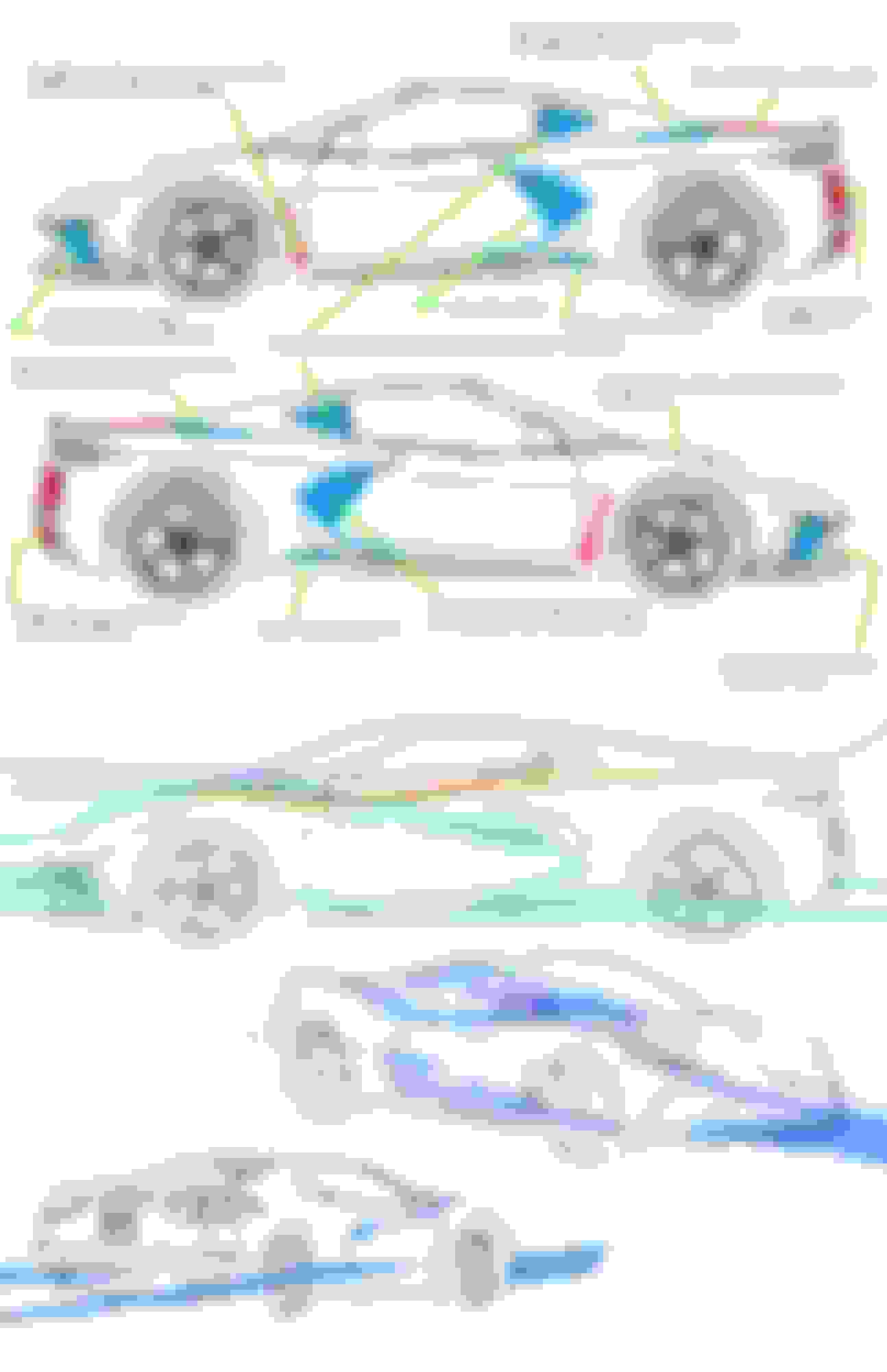
The first drawing shows the c8 outline superimposed on some of the competition to visualize where the airflow,aero and cooling inlets are in relation to the imagined ME. All the inlets and outlets are in the ballpark of similar designs to one degree or another. I imagine there will be vectoring/sculpted surfaces and potential winglets or other directional air guides to help funnel air to where it needs to go.
The second drawing is to help visualize the cooling and ducting features bith known and presumed and projected airflow of the ME based on similarly designed cars aerodynamics. Of course this is not scientifically proven, just an artistic guess for fun.
BTW, the side scoop shown in the drawing is only a rough location/size place holder since we still don't know exactly what it looks like.
Last edited by firstvettesoon; 03-13-2018 at 06:53 PM.
For some fun imagining of the C8 cooling and airflow.
I imagine there will be vectoring/sculpted surfaces and potential winglets or other directional air guides to help funnel air to where it needs to go.
Of course this is not scientifically proven, just an artistic guess for fun.
Maybe fun for you, but painful for others. First, learn the colors that represent the pressure gradient.
Re thunk the side view a bit and came up with a new guess.
Still guessing at some major features. Maybe C7pimp will find his way here and comment...please?
The front of the rear fenders look strange in the spy images. Always thought there could be something like this intake there. Sort of a cross between a 488 C7 type intake.
Tried giving it more of a DBS stance as he suggested too.
Last edited by firstvettesoon; 03-14-2018 at 04:13 PM.
Re thunk the side view a bit and came up with a new guess.
Still guessing at some major features. Maybe C7pimp will find his way here and comment...please?
The front of the rear fenders look strange in the spy images. Always thought there could be something like this intake there. Sort of a cross between a 488 C7 type intake.
Tried giving it more of a DBS stance as he suggested too.
I'm praying to Odin that you're moving in the right, Stingrayish, direction. A modern ME in terms of technology and aero with the flavor of a shark. That would be bold as all F***.
A is the stock OHV engine side, B is the wider Zorra side. The weight at the rear wheels should not be more than 60%. Total weight must be as light as possible. A C6 Z06 and a new P GT3 weigh the same. 3400 is tops. The Ford GT 40 that won LeMans in 66 weighed 3400lbs. Very very heavy.
Cooling for an 800 hp car and all it's systems is complex. FE cars have these systems near the engine. 52/54% rear weight bias is ideal for a front engine car. The C5 had this bias but a 2019 ZR1 needs a big wing.
Designing for cooling systems requires unique intakes. Depending on the system it will service. some will require high pressure to function and others less where there is suction.
For instance, the the front radiators for oil and water require air at a specific density and velocity to be efficient. (1,2 and 8).This requires 3 velocity and pressure changes each from inlet to exit. Very clever ducting is required. LMP and F1 cars require some very clever people to design their cooling systems at the sides of their cars.
The quality of the air at each intake will decide it's application. A NACA duct ((3) requires insipant or partial boundary layer separation to function properly. It generates it's own vortices that re attach and energise this layer. It is more efficient than a scoop but not necessary if it is used for the diff or gearbox cooling where there is a fan and an exit in a very low pressure region but it would be great for combustion intake. I don't think there will be an intake here. 5 and 6 will do this job.
Engine coolant and oil require the largest volumes and temperature capacity. No space at the back of this car for this, sides, weight distribution is more important.
The front radiators do the best job for this with some draw backs. Extra Plumbing and fluids add more weight. 7 lbs per gallon for oil and 10 lbs per gallon for coolant.
The radiator (1) may be two different sizes for A and B. The exit ramp and restriction devices on the hood (8)can produce downforce with the Meredith effect. The hotter air directed over the roof can reduce drag also.
A big gaping hole above the splitter is not good for downforce. When NASCAR does qualifying runs, they close off the holes. Their radiator doesn't exit out of the hood either.
5 and 6 side intakes will be different for cars A and B.
3 or 10 is an ideal place for combustion intake. It will go directly into the compressor or the plenum for the N/A engine. It's the coldest. I'd love to see a shaft driven compressor driven by the compressor like F1 cars have. Why have cold stuff next to hot stuff? 10 would be best for that.
The intercooler (9) gets engine coolant. I don't like the intercooler there but it is the best for reducing throttle lag.
5 and 6 can also perform the duties of 3 and 10. 4 A is for gearbox cooling and 4B is for ediff clutch cooling. DCT will require a larger cooler.
7 is a very low pressure extraction outlet for both.
5 and 6. 3 and 10 may not exist but I'm fairly certain 10 will be used for combustion intake. It gets sucked.
Maybe instead of being called a Stingray, it would be called a �Shark.� From its side view, it is starting to look like a shark. Good call IronV!
The front fascia/hood could use some more shark treatment (but as that remains hidden from view, hard to know). I keep coming back to two of c7pimp�s comments about the front and the hood itself, that:
Originally Posted by c7pimp
The whole front as a complete design is really something special IMO. The hood is going to be polarizing IMO but I love it.
firstvettesoon, if/when you have time, could you please re-imagine the front end a little to give us a taste of �matching shark?�
Maybe instead of being called a Stingray, it would be called a �Shark.� From its side view, it is starting to look like a shark. Good call IronV!
The front fascia/hood could use some more shark treatment (but as that remains hidden from view, hard to know). I keep coming back to two of c7pimp�s comments about the front and the hood itself, that:
firstvettesoon, if/when you have time, could you please re-imagine the front end a little to give us a taste of �matching shark?�
For some fun imagining of the C8 cooling and airflow.
The first drawing shows the c8 outline superimposed on some of the competition to visualize where the airflow,aero and cooling inlets are in relation to the imagined ME. All the inlets and outlets are in the ballpark of similar designs to one degree or another. I imagine there will be vectoring/sculpted surfaces and potential winglets or other directional air guides to help funnel air to where it needs to go.
The second drawing is to help visualize the cooling and ducting features bith known and presumed and projected airflow of the ME based on similarly designed cars aerodynamics. Of course this is not scientifically proven, just an artistic guess for fun.
BTW, the side scoop shown in the drawing is only a rough location/size place holder since we still don't know exactly what it looks like.
I think these pretty much hit the nail on the head so to speak.
Really fits the IVER’s McDonald’s car, especially the highlighted, “hollowed-out” area.
Adding a NACA intake duct to that area creates an especially efficient aero means of adding either more cooling to heat exchangers in the rear corners of the car, and/or adds to what Ferrari calls “base bleed” for the purpose of reducing drag — with the air “exiting the car” through the “below taillights” large vents.
Well done firstvettesoon.
Last edited by elegant; 03-14-2018 at 10:34 PM.
Reason: Fix typo; add picture.
I agree and that's great information....it sort of makes sense and does "look" like the spy images in that area, but c7pimp has not commented or confirmed this feature.
Hoping he and ZERV will fill in some more blanks soon.
Last edited by firstvettesoon; 03-14-2018 at 11:44 PM.
I agree and that's great information....it sort of makes sense and does "look" like the spy images in that area, but c7pimp has not commented or confirmed this feature.
Hoping he and ZERV will fill in some more blanks soon.
I fear C7 Pimp has been disappeared. Out in the wasteland of abandoned Detroit mansions... is a freshly dug hole in a basement.
Re thunk the side view a bit and came up with a new guess.
Still guessing at some major features. Maybe C7pimp will find his way here and comment...please?
The front of the rear fenders look strange in the spy images. Always thought there could be something like this intake there. Sort of a cross between a 488 C7 type intake.
Tried giving it more of a DBS stance as he suggested too.
Guesses are one thing, educated guesses are another.
There is a huge difference between your intake and this one. Quit with the 'fake' news. You simply don't understand. Your fans don't understand that your pretty pictures can't possibly work.
Adding a NACA intake duct to that area creates an especially efficient aero means of adding either more cooling to heat exchangers in the rear corners of the car, and/or adds to what Ferrari calls “base bleed” for the purpose of reducing drag — with the air “exiting the car” through the “below taillights” large vents.
This is not a NACA duct. Google it, why don't you.

 03-13-2018, 06:09 PM