When you click on links to various merchants on this site and make a purchase, this can result in this site earning a commission. Affiliate programs and affiliations include, but are not limited to, the eBay Partner Network.
^^^The pic that Shaka has up - which I think is a later in time mule - the bottom of that inlet curve doesn't appear to curve back to the front of the car like some of the recent drawings.
Which would make sense, as it's going to need a rocker/splitter shelf to direct the airflow into it.
Thus, I think the drawing having the bottom of the side inlet aggressively curving back toward the front of the car ain't it.
La Ferrari has a consistent design theme. Compare the air intake to the quarter window area. And, a bunch more around the car. Please GM do something stellar!!
Yup, I've been saying there is no quarter window for a while. Ferrari has a nice clean line there with the curves all flowing together. I'm sure the C8 designers have noticed.
^^^The pic that Shaka has up - which I think is a later in time mule - the bottom of that inlet curve doesn't appear to curve back to the front of the car like some of the recent drawings.
Which would make sense, as it's going to need a rocker/splitter shelf to direct the airflow into it.
Thus, I think the drawing having the bottom of the side inlet aggressively curving back toward the front of the car ain't it.
I think we are seeing two different designs. This car was started long before the C7 maybe before the C6. Looks mighty dated to me.
^^^The pic that Shaka has up - which I think is a later in time mule - the bottom of that inlet curve doesn't appear to curve back to the front of the car like some of the recent drawings.
Which would make sense, as it's going to need a rocker/splitter shelf to direct the airflow into it.
Thus, I think the drawing having the bottom of the side inlet aggressively curving back toward the front of the car ain't it.
Seems clear that there are/were different versions of mules with different side scoops, as you would expect. They are experimenting with different designs to optimize air flow. But as C7p said, the La Ferrari side scoop is the closest to what he saw and that matches up with the Road & Track photo. If you are going to copy a side scoop, the La Ferrari scoop would be the best choice.
Many of my earlier renders had LaFerrari style scoops. C7 said it is a continuous curve.
My latest side view shape based on the CAD/C7pimp shape matches up with the spy pic shape Shaka reposted when accounting for perspective. The major difference being the bottom lead in ramp.
Older spy pics did show a scoop beginning low on the door sill.
Last edited by firstvettesoon; 02-22-2018 at 07:00 PM.
Many of my earlier renders had LaFerrari style scoops. C7 said it is a continuous curve.
My latest side view shape based on the CAD/C7pimp shape matches up with the spy pic shape above when accounting for perspective. The major difference being the bottom lead in ramp.
Older spy pics did show a scoop beginning low on the door sill.
Doesn't the Road & Track photo show a "continuous curve" until it hits the rocker? If the La Ferrari scoop were curved instead of straight, would that solve the issue?
I think we are seeing two different designs. This car was started long before the C7 maybe before the C6. Looks mighty dated to me.
A mid engine project was started before bankruptcy then shelved. Possibly some of the early camo mules with squared edges were resurrected from that time.
Perhaps others might like these ME mule wheels better?
I look at a designs from a physics point of view first. You can have a heavier wheel provided the mass is reduced at the extremity as in this case. The math for a rolling wheel is more complex than the rigidity in space for rotating mass but in one plane it is uniform. There is far less precession in this design than the other wheels we have seen for the ME Vette. This and total mass in suspension design, particularly shock tuning, is an immense challenge. Technology creeps in everywhere.
My buddies 250 diesel Ford had a blow out at the rear. We had to figure out how to get the spare and work the jack. We thought we would have a problem with a very heavy huge wheel. We couldn't believe how light it was. One person can pick it up without any strain. Michelin replaced all four for nothing even though the vehicle had 20 000 miles. Talking about Michelin, Michelin owned Citroen and designed the DS suspension but also made 40 sets of carbon fiber wheels for their rally cars in the early 70s. That's right, carbon fiber. Talk about light. Michelin made 40 sets in aluminum. My buddy has an SM also with these wheels at $2000 each. Michelin also made the first radial tire and steel belted tire. The 55 DS was the first cat to have disc brakes for a production car. Sorry, I digress.
Those heat exchangers could be a split radiator for the engine coolant. The CAD drawings also show a front trunk mounted in the nose of the car, so the center grille could only be used for the A/C condenser.
The rear quarter panel scoops would be used to feed intake air to the engine's air breather(whether it's NA of forced induction) that the CAD drawing show mounted at the rear of the engine, above the transaxle, and to the transaxle heat exchanger and a engine oil cooler. Those two large scoops would also be used for the twin turbo's heat exchangers, if the car is equipped as an optional engine choice.
If those two large openings under the headlights are only for turbo's heat exchangers, and the engine coolant radiator is located where the CAD drawings show the front trunk, then only some small scoops would be necessary for the engine's intake air supply needs at the rear of the car.
Wasn�t saying that the openings under the headlights could be for the turbochargers. I just meant that if they�re putting multiple heat exchangers up front, they probably had no place to put them in the rear. There�s a diff cooler, trans cooler, oil cooler, engine radiator, and multiple auxiliary coolers. Moving a few of those to the front of the vehicle would allow for better, more efficient cooling.
Hate to say it, but what you may be seeing in the wild is most likely the new mid engine Cadillac to compete with the new Honda NSX.
Take a look at the engines being develop for the new mid engine models, and they are screaming Cadillac engines, not Corvette engines instead.
Just because GM extolled the benefits of an outdated engine design does not mean that they thought that their OHV design was actually current. It would be difficult to convince an international audience that your OHV engine is the latest and greatest. Current Cadillac designs are targeted at a more sophisticated audience than the C7 Corvette. The C8 will be an international HALO car. Coveted by young men all over the world!
Still seems surreal that a TT V8 mid engine corvette is on the horizon............
Yep. The times are changing. It�s to be expected, though. GM went from the ugly and sloppy C3 to the C4, digital gauges and all. The C5 put the Corvette up there with the big dogs, winning both Le Mans and the majority of Magazine comparison tests. I remember when everyone thought that the LS2 corvettes were fast, which they were back then. 420hp was a big accomplishment at that price point. Then the C7 hit and the crowd goes wild. The design language was completely different but completely Corvette. Round taillights leave, quad exhaust stays, rear glass gets smaller, and the Corvette gains sharp creases. But the engineers killed it, beating most supercars in most performance measures at a fraction of the price. After the Z06 came out, we thought it couldn�t get any crazier. Three years later, we have a 755hp ZR1 available with two transmissions, coupe or convertible, and a wing the size of a bar. Crazy is the new normal. It�s crazy to see a Twin-Turbo V8 Corvette, but it�s pretty cool to see Zora�s dream come true. I think he�d approve of project ZERV, but I know I do.
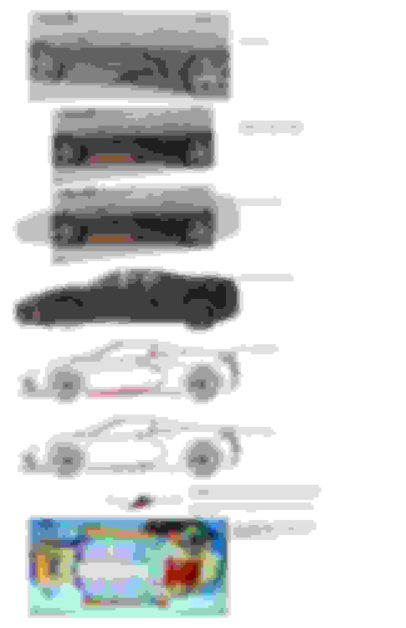
c7pimp used the words “smooth and continuous” to describe the curvature of the intake vent’s front edge. Those were were used in reaction to firstvettesoon’s earlier rendering in the first picture below.
At the same time IMO “smooth and continuous” means no corners, but it does mean we need to go to the second step of being a “constant radius curve” — which is what I am close to seeing in the second picture below. That second rendering is not exciting to me in regards to that vent’s front edge radius.
I believe that the final rendering we see from firstvettesoon (and later on the ME) has both a smooth and continuious line yet with a progressive difference in radius,specifically as to move down and away from the door toward the rear, at roughly 2/3’s of the way down toward the rockers, it gets to be a tighter radius curve — thus giving it much more “visual character” than the “letter C” as in that above, second, last/modified ACS rendering, and thus more consistent with the third picture below.
I looked at C7pimps drawing again and compared it to the first c8 spy shots. The only ones where a scoop was actually visible and although it is onle an old test car, it may lend clues.
Note that this cars scoop starts low - at the bottom of the door. It is wider at the bottom than at the top and has a curved ramp up and in the intake hole about mid wheel.
Note C7pimps drawing. I didn't look close enough before but I think he may be suggesting the scoop is wider at the bottom than the top and he said the doors turn in and down so this makes sense.
He also described the curved ramp up from the bottom.
The CAD shows the actual inlet "hole" mid wheel height.
From these clues I redrew the ISO to closer match his description.
I show two versions with slightly different curves. It is hard to estimate the actual curve from 3d to 2d without taking a lot of time.
Let me know thoughts. I think it looks more correct.
Last edited by firstvettesoon; 02-22-2018 at 09:37 PM.
I looked at C7pimps drawing again and compared it to the first c8 spy shots. The only ones where a scoop was actually visible and although it is onle an old test car, it may lend clues.
Note that this cars scoop starts low - at the bottom of the door. It is wider at the bottom than at the top and has a curved ramp up and in the intake hole about mid wheel.
Note C7pimps drawing. I didn't look close enough before but I think he may be suggesting the scoop is wider at the bottom than the top and he said the doors turn in and down so this makes sense.
He also described the curved ramp up from the bottom.
The CAD shows the actual inlet "hole" mid wheel height.
From these clues I redrew the ISO to closer match his description.
I show two versions with slightly different curves. It is hard to estimate the actual curve from 3d to 2d without taking a lot of time.
Let me know thoughts. I think it looks more correct.
Great job, I think the bottom one looks better... less “C” there...It’s a subtle difference but it’s significant. Crazy how super minor alterations change the look...
Take a look below...look at the curve I included, isn’t that curve closer to the CAD imagine curve?
Last edited by Paulchristian; 02-22-2018 at 09:54 PM.

 02-22-2018, 06:44 PM