When you click on links to various merchants on this site and make a purchase, this can result in this site earning a commission. Affiliate programs and affiliations include, but are not limited to, the eBay Partner Network.
November 23, 2021The driver�s outside rear view mirror on some 2020-2022 Corvettes may have poor operation and appearance, including numerous lines shown in the mirror and a dim reflection at all times. (Fig. 14)
Fig. 14
The poor appearance may be caused by the installation of an aftermarket radar detector in the vehicle. Depending on the installation location, the aftermarket electrical device may cause higher voltage to the mirror.
If the damaged mirror appearance is shown, check for the installation of a jumper harness to power the radar detector added to the mirror�s X1 connector. The connector is located behind the front cover of the inside rearview mirror. (Fig. 15)
Fig. 15
Disconnecting the jumper harness, and replacing the damaged outside rearview mirror due to the jumper harness, must be authorized by the customer. Vehicle damage resulting from aftermarket devices is not covered under warranty.
For additional information, refer to Bulletin #21-NA-251.
Well, I'm not an engineer, but this has got to be the craziest cause - effect relationship I have ever seen! I have my Valentine One, gen 2 connected to to the rear view mirror power source (red and black wires in the window stalactite) for the past year (2020, HTC, 3LT) and have had no issues. Anybody out there have experienced this driver side mirror issue?
Al Engel "Save the Wave"
Last edited by Al Engel; Nov 24, 2021 at 03:38 PM.
Reason: spelling
Makes me wonder what KIND of radar detector is being called responsible for INCREASED voltage to the outside mirror. I'm not an engineer, but I worked as an electrician for nearly 40 years and never heard of one device that consumes power causing and increase in voltage to another device in the same circuit.
NIce to know that since they are blaming this power point in order to avoid warranty claims, that one should remove that wire AND the detector before taking the car in for service.
Interesting. I think JerryU had that mirror problem and uses a radar detector, and I think he tapped into the rear view mirror harness.
But I'm curious how tapping into the inside rear view mirror harness causes a high voltage problem for the outside mirrors.
Interesting. I think JerryU had that mirror problem and uses a radar detector, and I think he tapped into the rear view mirror harness.
But I'm curious how tapping into the inside rear view mirror harness causes a high voltage problem for the outside mirrors.
Yep, I had that happen to my Driver's side mirror after I got my C8 on September 2nd. The photo's I took were on September 11.
Can't tell for sure when I tapped the mirror for my ~8 year old Escort Max Radar Detector but it was close in time. I think it was after. However I do know it occurred when I came out of a store 10 miles from my home because I wondered if someone had possibly hit it! It was fine when I dove to the store.
The dealer replaced the mirror on warranty and said they had seen similar BUT usually older cars. I have had the same detector connected the same way with a Blendmount mirror tap since.
Can't see how this detector can: 1) cause a voltage spike and 2) it hasn't with the new mirror in 14 months!
^^^
Yep, my point with mine is if it hasn't happened in ~14 months AFTER my new mirror install it's not going to happen!
If in fact I installed the Blendmount wire tap before I had the mirror issue (as I installed both around the same time) been no issue since the dealer installed the new mirror (on warranty.) So not logical it occurred one time and not after. Also I know it did not happen right after I installed the detector power using the mirror tap (If I did in fact install it 1st) as I did that while in the garage and it was fine right after as I look at the mirror carefully as I back out to be sure I am clearing the wood garage door molding.
First I saw it was when leaving a store where (as usual) I was parked at the end of the lot with no other cars around. Recall when I saw that unusual pattern thought someone may have passed and hit it! Looked all over for any other marks on the mirror housing and there were none! Then with a google search saw that it is a failure of the automatic night diming feature. Dealer Service Manager and Corvette Tech said they had seen that before but on older cars.
BTW, Tech installed the new mirror in ~10 minutes. He used a wood stick to reach behind the mirror and released from the clips that hold it in place. Unplugged the electrical connection, plugged in the new mirror and snapped it back on the clips.
Found this video that will show where the clips are and how this fellow unclipped:
Anybody else experiencing side mirror issues, with or without radar detector? If 'with radar detector', what brand / model detector and how did you wire it for power?
Anybody else experiencing side mirror issues, with or without radar detector? If 'with radar detector', what brand / model detector and how did you wire it for power?
Makes me wonder what KIND of radar detector is being called responsible for INCREASED voltage to the outside mirror. I'm not an engineer, but I worked as an electrician for nearly 40 years and never heard of one device that consumes power causing and increase in voltage to another device in the same circuit.
NIce to know that since they are blaming this power point in order to avoid warranty claims, that one should remove that wire AND the detector before taking the car in for service.
Yes, I agree. I am an EE and I have never seen a LOAD added to a VSS supply that causes the supply voltage to INCREASE if we are simply dealing with Ohm's law. As the load increases, impedance is reduced, current is increased, and voltage DROPS. That is assuming the power supply isn't doing something active like current sensing and adjusting output dynamically which might increase the supply voltage. You would think there would be a voltage regulator there that is doing a good job of keeping the supply side around 12-13 volts though. The C8 does have a complex power conditioning system I am told. (I saved the details on it, see attached! )
I can't see a radar detector generating the kinds of loads to cause major swings in the load.
That said, I am using a V1 G2 and I have noticed my driver side mirror looking TOO DARK at times when driving at night. I assumed this was because it was trying to dim the high beams of cars driving behind me. Next time I notice this, I will disconnect the V1 and see what happens.
Wonder if there is a high voltage DC-DC converter in the radar detector that is sending some high voltage spikes back through the supply?
I am also wondering if this could be caused by static electricity charge around the surface of the vehicle (gaussian surface), where the mirrors act somewhat as "cusps" where charge carriers will concentrate. You step out of the car while pumping gas or something and if you touch the mirror, you complete the path to earth/ground and might cause damage to the mirror in the process.
Someone with access to the pin outs is claiming at the harness taps into pin 9 of the X1 connector, which on the C8 connects to the ground on the dimming mirrors. Harness should be tapping into pin 5 as ground instead. Sounds like GM knew about the voltage sensitivity of the mirrors to the ground line and thus created a dedicated ground, which is now being improperly used. That would make sense, as overvoltage on the supply side shouldn’t cause an issue due to the engineering tolerances but if they mess with the ground voltage on a dedicated ground line for the mirrors, then that can create problems. Need someone with a harness to confirm the pin out.
Several people, with both Corvettes and other GM cars, have reported having this mirror problem even though they never used a radar detector at all. I think GM is trying to weasel out of warranty repairs.
Someone with access to the pin outs is claiming at the harness taps into pin 9 of the X1 connector, which on the C8 connects to the ground on the dimming mirrors. Harness should be tapping into pin 5 as ground instead. Sounds like GM knew about the voltage sensitivity of the mirrors to the ground line and thus created a dedicated ground, which is now being improperly used. That would make sense, as overvoltage on the supply side shouldn�t cause an issue due to the engineering tolerances but if they mess with the ground voltage on a dedicated ground line for the mirrors, then that can create problems. Need someone with a harness to confirm the pin out.
Hrmm, usually you would try to use a common ground for everything to avoid "ground loops". Why would the special ground for a side mirror be found all the way up in the rear view mirror wiring harness / connector? That makes little sense to me.
If anything, it should be a homerun from the side mirror to the main grounding point either on the battery or the power supply/regulator body, which should be directly bonded to the battery.
I would like to see the pinouts for the camera connector too. From my "memory", I believe I made my connections like the following:
This is looking from the passenger side of the connector. DO NOT USE THIS DIAGRAM, it is just to show where I think mine was tapped.
I used a volt meter to test for +12v, but I don't think I checked the impedance of the GND pin to the battery GND. Now I have something to run and check on... Should be very close to 0 ohms....
For grins, I could probably setup some RJ11 jacks and tap the power on my V1 and then check the +12V and GND leads on my DSO. Might be interesting to see how clean that power looks.
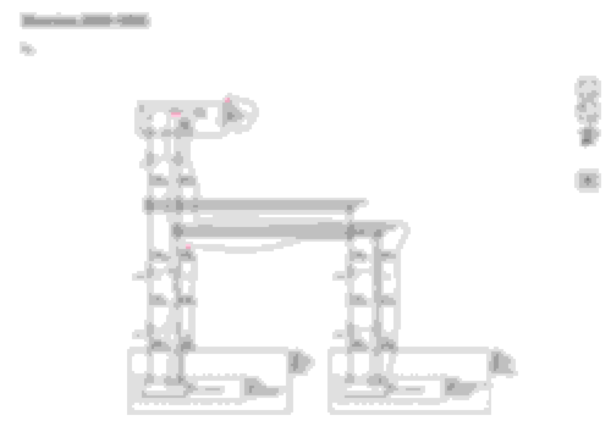
Attached are two schematics from the 2020 Service Manual that are relevant to the discussion. I have some background in reading schematics, but I am not familiar with some of the symbology. I can, however, recognize the ground symbols, and I think the connectors, and pin numbers may be indicated here. The first one, from page 3404, is an inside rear view mirror schematic. You can see a line coming from "Outside Review Mirror Schematics", via what I think is pin 8 on connector X1 (alternate interpretations welcome). But what is interesting is that line from the oustide mirror terminates at the inside rearview mirror with a ground symbol-Confirming the idea that a line runs all the way from the outside mirror to a ground on the inside mirror. Another line from the inside mirror appears to go through X1, pin 5, to a direct ground G201. The second schematic is the relevant Outside Rearview Mirror Schematic, showing both outside mirrors with wires going through several connectors, all the way back to where they terminate in a ground symbol at the inside rearview mirror. Again, confirming that both outside rearview mirrors use a common ground at the inside rearview mirror. The outside rear view mirrors show no other path to ground in this schematic. The mirrors have multiple functions, and the there are multiple schematics for those functions. I just selected the two that seem to show a shared ground with the inside rearview mirror. Other functions could have additional paths to ground - I did not check for that.
Inside Rear View Mirror Schematic - showing connection from Outside Rear View Mirrors terminating at the inside mirror with a ground symbol. And, showing a connection from the inside mirror to ground G201. Shows how the Outside Rear View Mirrors and Inside Rear View Mirrors share a common ground that terminates at the Inside Rear View Mirror. I verified that both of these are in fact symbols for ground,or chassis.
Last edited by Andybump; Dec 14, 2021 at 01:38 PM.
Well, I think this solves the mystery. Thanks for posting the schematics!!!
I will post some pictures shortly, but my recollection of the number of pins on the X1 was too high. It is a 10 pin connector.
From the schematic, the pins to use are PIN2 for +12V/IGN and PIN5 for GND. PIN5 is BLK/WHT cable behind the mirror.
I indeed used the lower row of pins for GND (was easier to get to it), and that was PIN8 which is BLK/YEL and does connect to the outside mirror (and supposedly to GND also). There must be a ground loop there and PIN8 should be avoided.
That said, my driver side mirror looks fine. No LCD burnout...to be honest, I don't like the dimming mirror feature and would rather just disconnect the mirror and call it a day. Anyone know where the X500 or X501 connectors are located? Maybe I just need to de-pin X1 pin 8 and pin 9 at the mirror connector?
JerryU, did you use PIN 5 or PIN 8 for GND? I am hesitant to move my gnd pin when things are working and no damage after thousands of miles of use.
Regarding the ground symbols, the one that looks like a wifi symbol is usually the "earth gnd", which in a vehicle I would assume means a home run to the battery NEG terminal. The symbol that looks like a rake is the symbol for the "chassis" ground, which would mean connecting the gnd to something nearby and metallic, and HOPEFULLY grounded connected. With dissimilar metals, glues, paint, etc, all sorts of things can go wrong with a chassis ground where you are relying on current to flow through those junctions. This seems reversed based on their schematics though. PIN5 shows a chassis ground. PIN8 shows a homerun to NEG- terminal and that ground is very close to the X1 connector. You would not expect ANY current to flow the direction of the side view mirror if that schematic is correct. It might be correct logically how things are connected, but probably not correct based on the actual wiring hardness / pathways. Also, the mirror schematic shows NO additional connections to ground, just the connection to PIN8 on the X1 connector. It really makes no sense that current could flow in that direction from a Thevnin/Norton mesh nodal analysis standpoint.
.
Last edited by dohabandit; Dec 14, 2021 at 02:31 PM.
Also, the mirror schematic shows NO additional connections to ground, just the connection to PIN8 on the X1 connector. It really makes no sense that current could flow in that direction from a Thevnin/Norton mesh nodal analysis standpoint.
.
Just want to point out, there are other functions in the mirror, and I think there are different schematics for them. So, while these schematics show a shared ground, and related pins for the dimming circuit, it does not exclude the possibility of another ground path for the mirror video display. I did not search all the schematics.


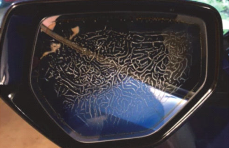 Fig. 14
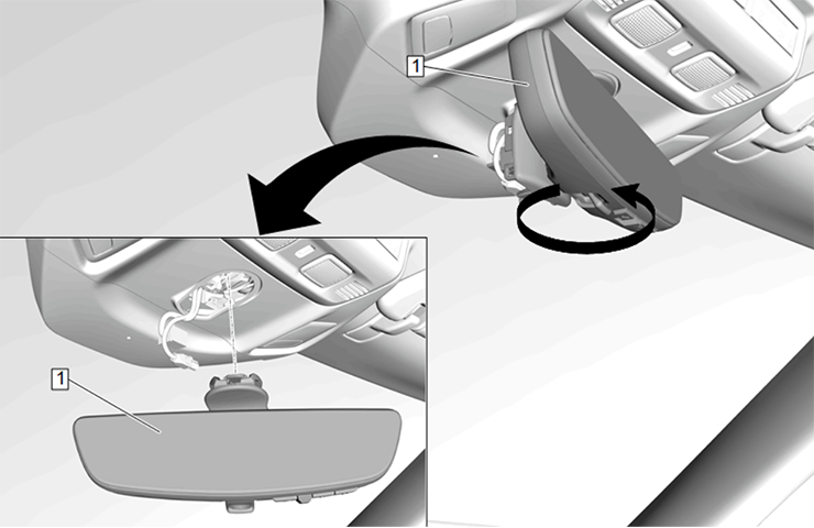 Fig. 15