When you click on links to various merchants on this site and make a purchase, this can result in this site earning a commission. Affiliate programs and affiliations include, but are not limited to, the eBay Partner Network.
Hey Dan,
Just wanted to say that you are doing a great job. Thanks for all the great pictures and please keep them coming as I am learning. I am on the cusp of starting the bodywork on my 1969 and seeing you coming up with the results with Dub's help inspires me to move forward with my repairs.
Thumbs up
Pete
well on the 8/22/17 you were just trialling different glass mats and cloths . by 9/12 you casually show a really nice 3 angle large piece MISSING corner repair .
outstanding
you have got the (fibreglass repair ) bug now ,I had a laugh when you mentioned the "Backlight for dramatic effect" ..
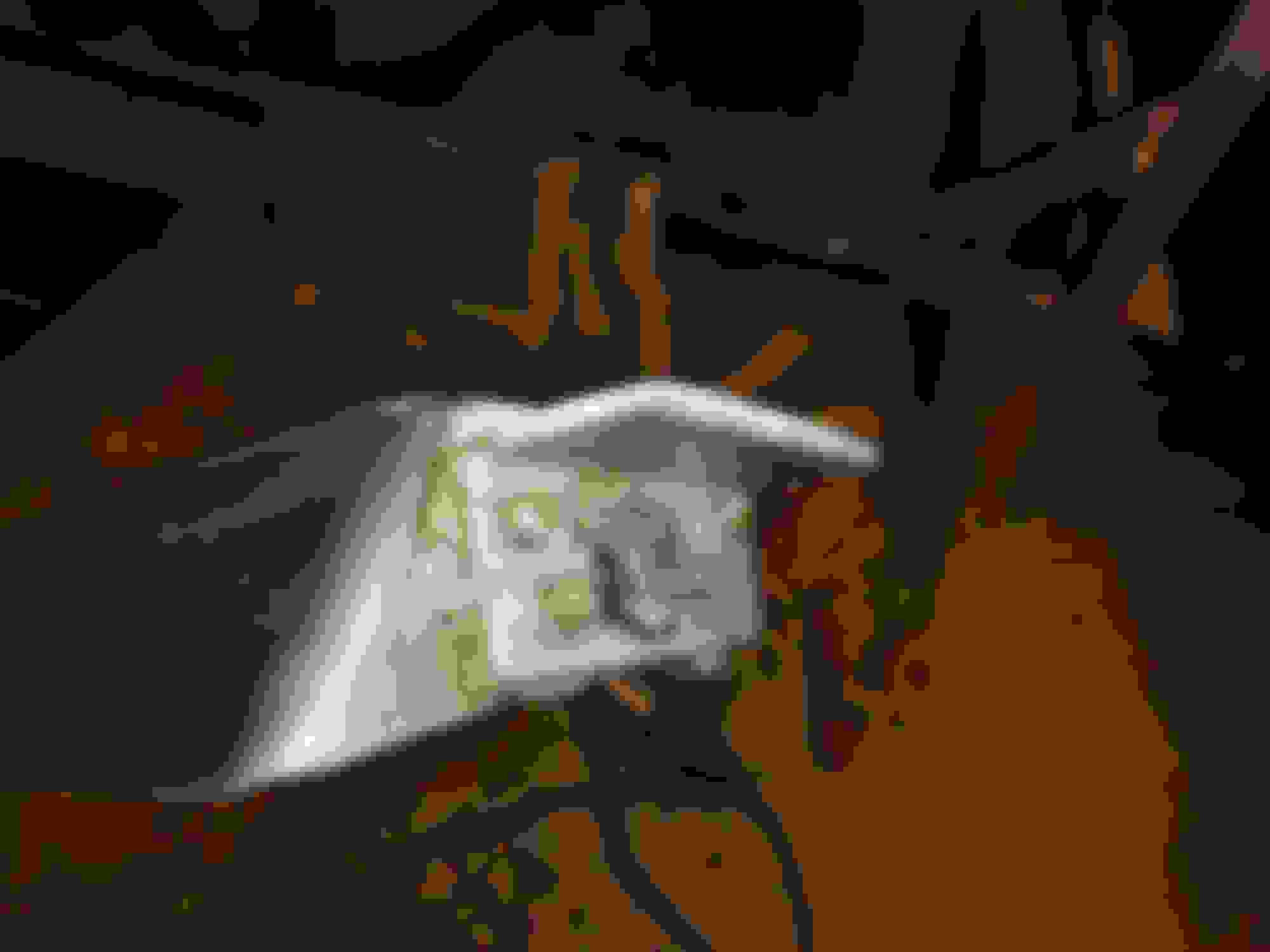
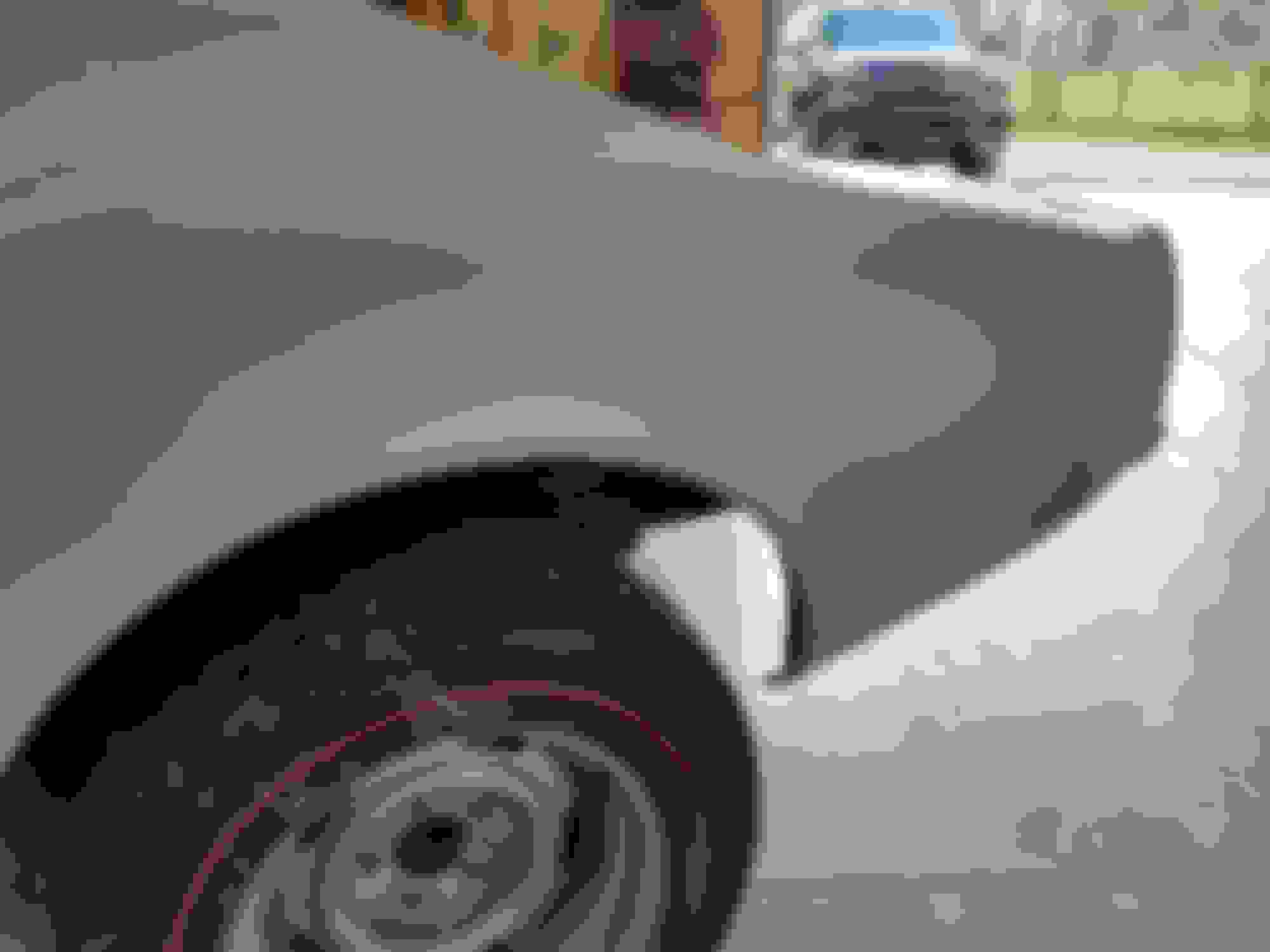
The area on the very corner where the bumper is touching is smooth...meaning there is no raised pad with defined crisp lines in it. There is one there...but it is so subtle that many may not see it.
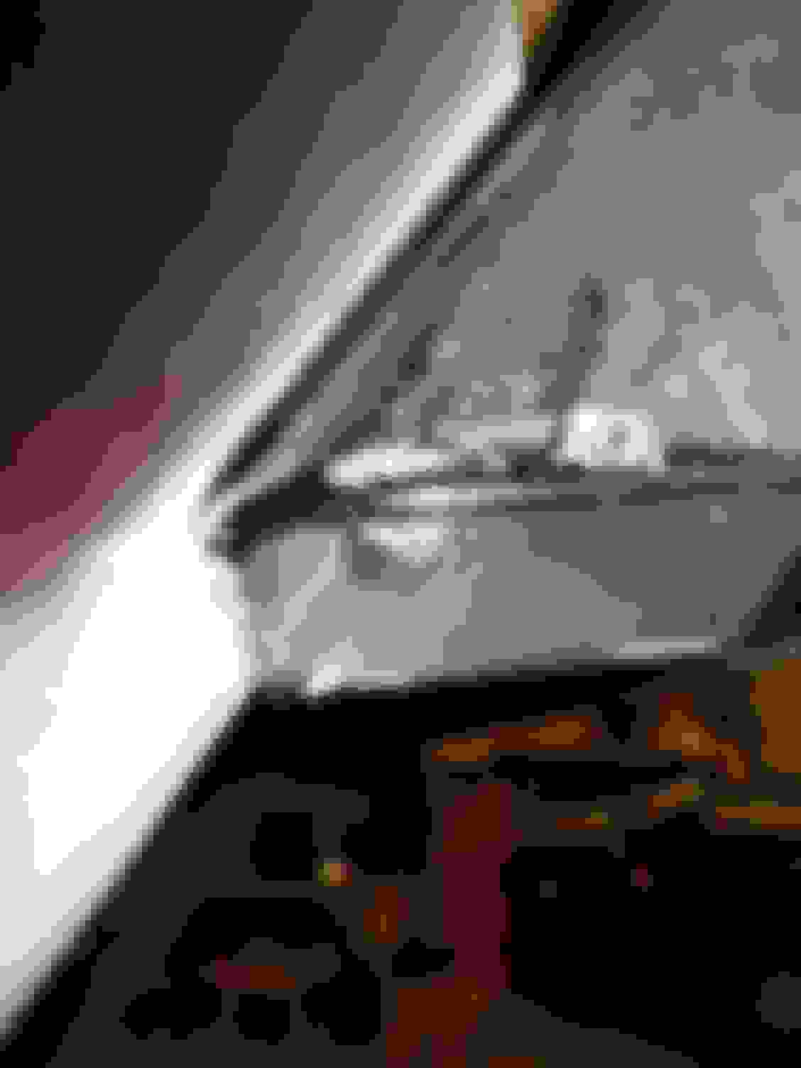
When you are installing the bumper....and you have it touching and up against the quarter panel near your side marker light...and then it wraps around to the rear. I make sure that the bolt by the side marker light is in place and that the bolt for the bumper by your license plate mount area is also in. THEN I look at the corner mount area and adjust accordingly.
***TRICK***
I can see in your second photo in post#24. That you have a gap at the top where the bracket is touching the body at the bottom of the bracket.
When I have ones like this where I am going to be 'splitting the lesser of two evils'. I mask off the metal mount area on the bumper and prep the area where I will then apply VPA ...and using the flat surface where the bumper will be touching the body...the VPA will then be flat when I pull the bumper off when the VPA is beginning to set-up.
I know I would not try to build out a lot with the VPA....all I am looking to do it give the metal a little bit more flat surface to contact.
I'm going to bolt it up and make a template of the shape I need at the top corner, then laminate some fiberglass to bring the top out to better match the bumper mounting pad. Maybe someone will post a picture of that area...
This isn't the original bumper, so it's no surprise it doesn't fit correctly. The bumpers had rubber sheet pads on all the mounting surfaces, which probably helped with gaps.
The AIM shows the bumpers bolted tight to the fiberglass body. No spacers or pads.
I would be careful in making your body match this mounting pad perfectly. The reason is that you can actually mess it up by adding too much material than is actually required...and by doing this..you actually visually alter it appearance.
But do as you feel comfortable in doing. But do not say that you were not warned....and the only reason I am writing this is because I have had a few customers that wanted me to fix it and when I made it perfect...it looked like total crap...expect that the mount pad was perfect...but the surrounding area was not correct....and I actually ground off all I had applied.
I would be very leery of following the AIM torque spec (25-35 Ft-Lbs) for that mounting bolt with the bumper mounting pad not touching the fiberglass at the top. I would think that would put stress on the body and cause a crack?
Perhaps the better route would be to make an aluminum spacer that fills the void and allows the bumper mounting bolt to be tightened and not distort the body.
You would be surprised on how tight you can get these bots IF 'things' are correct.
IF all is correct...tightening up these bolts is not going to be able to compress the fiberglass.
Where I have seen 'problems' when the inner steel support or bracket is NOT laying flat against the FLAT fiberglass...and IF the bumper mount is at a really bad angle...you can crack something.
This is why I often times mention to people that they need to mount this stuff up and verify ALL is good...so they do not have any surprises when they are installing them AFTER it has been painted.
Not that this matters...but seeing what I am seeing in your photos...because I have seen it many, many times. I would use the VPA and not think twice. And knowing that the mount area for the bumper mount pad to touch the body does not have to be all inclusive to still be effective ane not cause any problems. And the reason I an writing this is because it is a fact..and I can not tell you how many factory built Corvettes where the bumper mount pads that touch the paint were NOT all touching the body perfectly flat.
Do whatever you want....just passing along what little bit I know about this stuff.
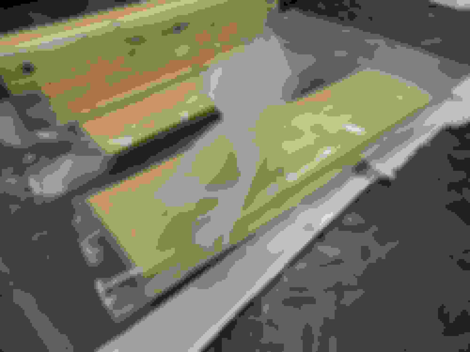
Finally got the bumper mount pad built up so the bumper mount flat area is touching right around the bolt. I ended up laminating a lot of layers that were eventually ground off to make it look right, as DUB foretold!
I built a crude jig to create the flanges for the rear valance panel.
A 2x4 with a piece of plywood screwed to the top.
Another 2x4 is clamped into the jig to press mold an angle piece to use for flange material. Drywall screws are used as depth stops and set at 1/8".
I wrapped the 2x4s in plastic for mold release, 4 layers of well saturated 1.5 oz. mat was laid in the jig, clamps applied and left overnight. It worked pretty well.
Now I need to create a curved jig for the missing exhaust bezel attachment flanges which attach to the inside of the rear quarter panel.
****Creating the bonding strip for your exhaust bezel mount area*****
To create the curve for your exhaust bezel...you can use the curve on the exhaust filler panel as a mold. I do when ever I need to make that bonding strip that goes on the backside of the 1/4 panel.
Thanks for the link, I haven't seen their catalog.
For $86, I think I will try my hand at making them myself.
How hard could it possibly be?
Dan
Dan,
I agree...but for me...sometimes buying them is actually cheaper for my customers due to I have to charge for my time and materials.
I have molds for many odd parts so that I can wing-up them if needed...but if it is part that I do not have a mold for...that is where the costs can vary.
I KNOW you have this one in the bag and should not be an issue at all.
Those are some serious holes and some nice repair work. I had some issues with my 69 rear quarter and the rear bumper holes. I had a doner car for the front clip replacement. I tried making a mold of both areas.
I realize many do not have donors but if they do.............................
 09-28-2017, 08:05 AM