When you click on links to various merchants on this site and make a purchase, this can result in this site earning a commission. Affiliate programs and affiliations include, but are not limited to, the eBay Partner Network.
Since it's a gloomy day I decided to go ahead and do the center cluster today.
I did NOT paint the housing white yet; just wanted to see how I would route the LED strips. Worked out well - so if the color is way too different from the speedo & tach, then I will remove and paint.
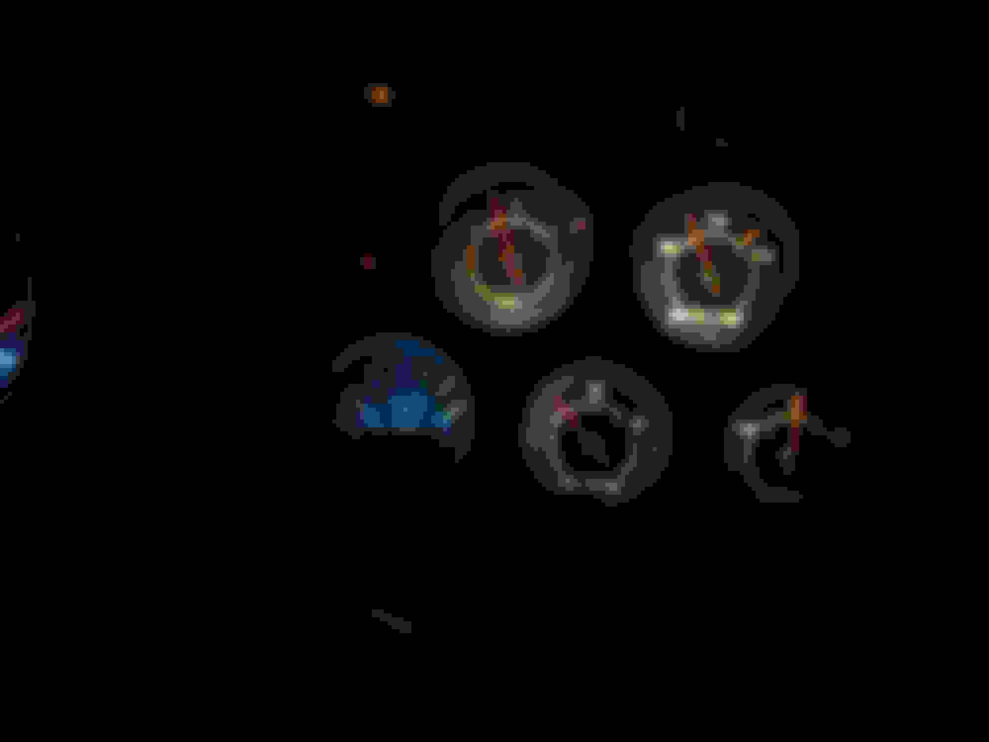
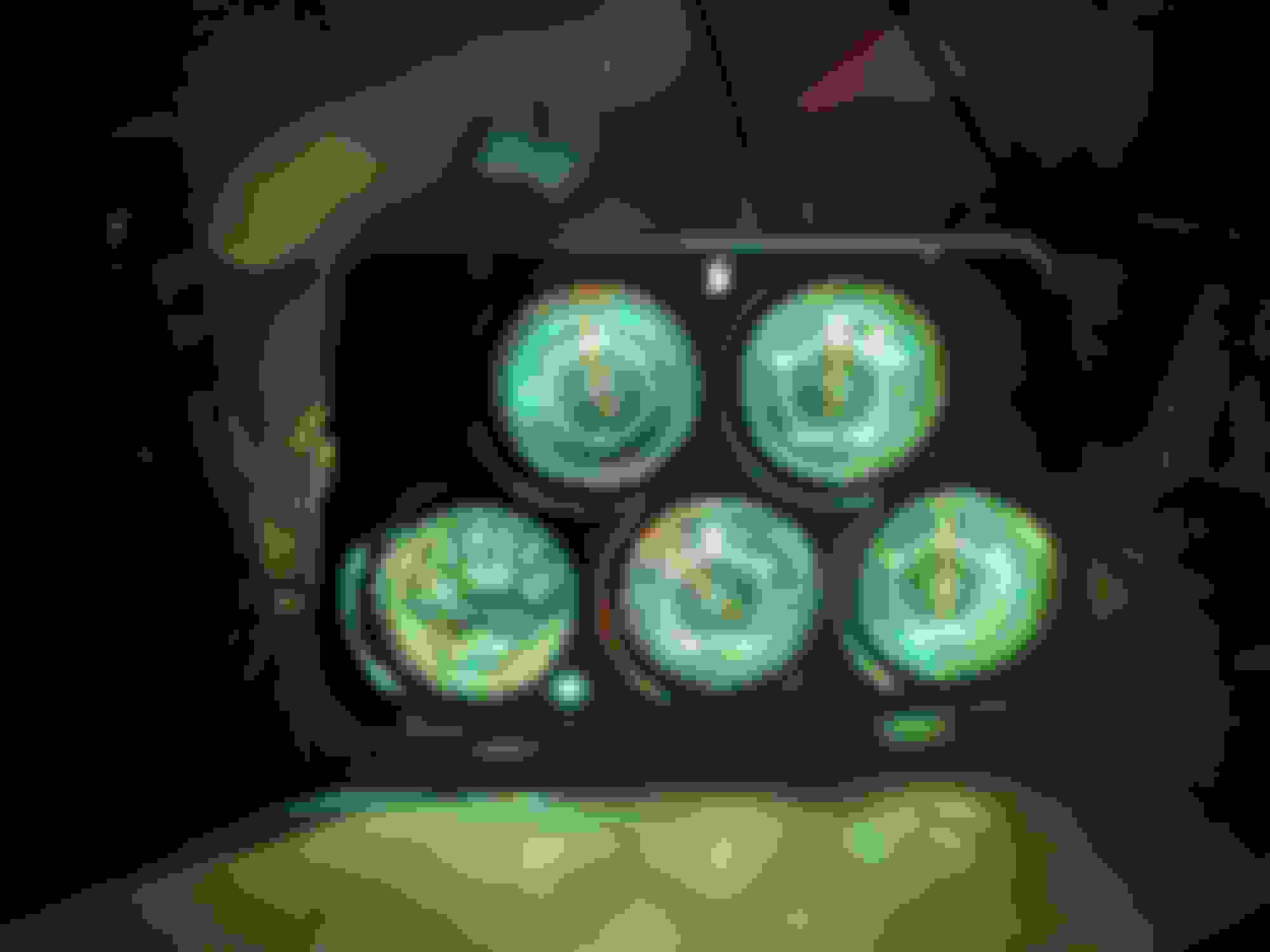
Here are the before and after pictures:
Last edited by carriljc; Aug 17, 2017 at 12:07 PM.
I'm old, but I like them bright. BUT - these things are dimmable anyway. AND you have multiple color choices too.
I was just going to live with that dim incandescent lighting, but those annoying lamps are a pain to keep in and I got tired of living with this or that lamp not working. Then, I saw these strip lights for like 10 bucks and decided, ah, what the heck? Not only that, I can always put the lousy lamps back in.
My next project will be the center gauge cluster--- see how that goes?
Anyway, here they are in RED while I was testing them on the counter:
I have my dash tore appart right now and am torn between going with your idea with the LED strips or just getting some blue LED bubls and replacing the orignals. I like the idea of having multiple colors to select from and am pretty handy with a soldering station and test light.
But I have a few questions.
1: Are you still using any bulbs in the sockets at all any more?
2: Where did you tie into the harnest or fues box to supply power for the LEDs?
3: You said they are dimmable but is that from a separate controler or the headlight switch?
4: Can I get a current link to the kit you used so I can see what all comes with it (your orignal link is dead)?
5: Where did you end up mounting the controler?
6: These just run off the 12 volt wiring in the car right or Is there a power converter in the signal chain?
7: What is this Air/Fule Ratio gauge you replaced the clock with?
I have the clock out of mine on the bench right now trying to fix it and its not coming back to life. So I'm thinking about maybe a quartz conversion kit or maybe that gauge you have there might be more useful cause I know a updated radio will have it's own clock.
i have my dash tore appart right now and am torn between going with your idea with the led strips or just getting some blue led bubls and replacing the orignals. I really hated that those lamps would fall into the housing, the lamp holder would not ground well, and/or the lamp holder would fall out of the back of housing...and this looked doable).
I like the idea of having multiple colors to select from and am pretty handy with a soldering station and test light.
But i have a few questions.
1: Are you still using any bulbs in the sockets at all any more? Yes. For the turn signals and high beam lights and brake-light. I also extended all those leads so that I can assemble the dash pad and still have plenty of length to comfortably do that before putting in place.
2: Where did you tie into the harnest or fues box to supply power for the leds? I bought a usb connector for a cigarette lighter, disassembled it, and soldered in the 12 vdc side to the lighting circuit (used 2 lamp socket leads - since leds use much less current i probably could have used just 1 lead but i had a bunch of spares).
3: You said they are dimmable but is that from a separate controler or the headlight switch? Dimmable from a separate controller. See picture below. There is a little "receiver" lead that hangs down slightly below the dash...barely visible.
4: Can i get a current link to the kit you used so i can see what all comes with it (your orignal link is dead)? This one looks the same and or similar (I'm thinking that these are the exact same ones actually). https://www.amazon.com/smartdio-bias...olor-led-light
5: Where did you end up mounting the controler? The controller is a remote controller, see picture below. I will attach a picture below. I keep it in the glove box. Never have used it since i installed it.....other than to play with it.
6: These just run off the 12 volt wiring in the car right or is there a power converter in the signal chain? See above.... 12 vdc->usb converter/outlet.
7: What is this air/fuel ratio gauge you replaced the clock with? Oh my i got that probably 20 years ago just because it kinda/sorta matched my gauges. From some place called CB Performance (LINK ADDED) http://www.cbperformance.com/default.asp.
To
i have the clock out of mine on the bench right now trying to fix it and its not coming back to life. So i'm thinking about maybe a quartz conversion kit or maybe that gauge you have there might be more useful cause i know a updated radio will have it's own clock.
Last edited by carriljc; Mar 15, 2018 at 12:35 AM.
Reason: clarifications and replaced "alternator" with "brake light", added CB Performance link
I actually liked these LED strips so much that I installed some under the kitchen counter so I have a picture of the USB input/converter/controller receiving lead/antenna (that little lead that hangs alone).
Here you are. I have a similar one(2 actually- 1 for speedo & tach, and 1 for center dash housing) installed behind the dash. Hope this helps. I also have a separate one for the center dash lights. I'll get in there one of these days to paint the center dash housing-internals white also. I really like these.
These are approximately 20" strips. Installed as follows:
1 LED strip in speedo housing
1 LED strip in tach housing
2 LED strips in center dash housing (for proper lighting overlap).
Last edited by carriljc; Mar 15, 2018 at 12:40 AM.
I actually liked these LED strips so much that I installed some under the kitchen counter so I have a picture of the USB input/converter/controller receiving lead/antenna (that little lead that hangs alone).
Here you are. I have a similar one(2 actually- 1 for speedo & tach, and 1 for center console housing) installed behind the dash. Hope this helps. I also have a separate one for the center console lights. I'll get in there one of these days to paint the center console housing-internals white also. I really like these.
These are approximately 20" strips. Installed as follows:
1 LED strip in speedo housing
1 LED strip in tach housing
2 LED strips in center consoling dash housing (for proper lighting overlap).
Will one controller run both sets of lights or do you have to have one for the dash and one for the center cluster? Also do you have a pic of how you ran the LED strips inside the center cluster? Thanks a lot I think I'm about to get my head wraped around this.
Oh my.... I don't know if have a picture. I will look around some. But I'm afraid I may have lost them all when my computer died last week. Let me look around a bit.
Originally Posted by Classic Muscle
Will one controller run both sets of lights or do you have to have one for the dash and one for the center cluster? Also do you have a pic of how you ran the LED strips inside the center cluster? Thanks a lot I think I'm about to get my head wraped around this.
Last edited by carriljc; Mar 15, 2018 at 12:36 AM.
Will one controller run both sets of lights or do you have to have one for the dash and one for the center cluster? Also do you have a pic of how you ran the LED strips inside the center cluster? Thanks a lot I think I'm about to get my head wraped around this.
There are two(2) control boxes behind the dash.
1 control box feeds 2 LED strips.
1 control box feeds the LED strips for the speedo(1 LED strip) & tach(1 LED strip).
1 control box feeds the 2 LED strips I placed within the center dash gauge cluster (to get proper lighting overlap).
I cannot find a picture of the way I laid the LED strips within that center dash gauge cluster. I was just a matter of experimenting.
Last edited by carriljc; Mar 15, 2018 at 12:39 AM.
I bought that air/fuel gauge from a place called CB Performance.
Here is a closer look: https://www.corvetteforum.com/forums...post1594041117
That red indicator lamp to the lower right (as you face it) is the indicator that the O2 sensor is warmed-up and working(it is where the old clock adjustment stem was located).
Below is the CB Performance website. I got ahold of them before I installed my LED lamps because I was looking for a replacement lamp. They told me they could only sell me the whole A/F Gauge and that they had one (1) left...this was probably a little over a year ago. I did not need a whole new A/F gauge so I installed a little blue LED (you can tell it was different in the pic below) in there shortly before I installed my strip lighting. You might want to give them a call- they might still have it since hardly anybody uses analog A/F gauges anymore....it's worth a shot. http://www.cbperformance.com/default.asp
Last edited by carriljc; Mar 15, 2018 at 10:20 AM.
I just noticed that, per your profile, you have a 1977. If I understand correctly - the 1977 center dash cluster is different from the earlier models, and more like the 1978 and later.
If so, then the layout for installing the LED strip in my model would be different from yours, so I do not think pictures from mine would help you much.
Last edited by carriljc; Mar 15, 2018 at 10:02 AM.
stingraymaniac- Looking good.
One of these days, when I'm feeling less lazy, I will go in there and paint the center cluster housing internals white also ---- it's a bit different hue right now since it is still that "light blue".
Went back into dash today and got picture of how I routed the the 2 LED strips inside the center cluster. YES- I routed 2 of the strips in here to get appropriate lighting overlap.
I am also going to paint it white while I have it out.
Originally Posted by Classic Muscle
Will one controller run both sets of lights or do you have to have one for the dash and one for the center cluster? Also do you have a pic of how you ran the LED strips inside the center cluster? Thanks a lot I think I'm about to get my head wraped around this.
Last edited by carriljc; Jun 13, 2018 at 11:18 PM.
I painted the insides white these last couple of days. Here is a side by side comparison - not the best because of other reflected light, but it seems a bit better (or just wishful thinking?):
Seems to me it's a bit less "blue" now in picture on the right..... either way, it seems a bit brighter than the incandescent lamps before (see below for comparison):
I showed the wife unit the different colors and she preferred one of the blues..... not my cup-of-tea so I'll stick with the the white LEDs.
And some other lamp colors just for info in case someone is interested in doing something like this:
blueish:
greenish:
There are like 15 different hues to choose from (some look quite terrible to me). I will just stick with the white lighting. They are dimmable also.
Last edited by carriljc; Jun 15, 2018 at 03:38 PM.
Reason: add detail & other color photos
I just put LED strips into my center cluster. When they are hooked up in the car, to the gauge lights, they won't power up all the way - they flash very rapidly, and the controller won't respond to the remote. They work fine off of the cigarette lighter. Any thoughts? Do I need to add a resistor?
I would suspect a faulty power supply lead.
......but you may just have gotten a bad strip, maybe damaged during installation.
Try changing the battery on your remote...you may have it on "flash".
No resistor should be needed.
Which LED lights did you get? Did you test them before installation? Are they for 12 vdc systems?
Originally Posted by Corby'sMarilyn68
I just put LED strips into my center cluster. When they are hooked up in the car, to the gauge lights, they won't power up all the way - they flash very rapidly, and the controller won't respond to the remote. They work fine off of the cigarette lighter. Any thoughts? Do I need to add a resistor?
I would suspect a faulty power supply lead.
......but you may just have gotten a bad strip, maybe damaged during installation.
Try changing the battery on your remote...you may have it on "flash".
No resistor should be needed.
Which LED lights did you get? Did you test them before installation? Are they for 12 vdc systems?
They worked from USB power in the house, they worked from USB power off the cigarette lighter. The remote works, verified with them on a different power supply. Currently, the system is set to stay on with white light.
They aren't flashing like a strobe, but like they are trying to power up multiple times per second. The plug adapter - which lights up when powered - does the same when they're plugged in, but is steady when they aren't.
Looks like mine and my setup. I suggest running a regular household extension cord and plug in a regular usb outlet to see how they work.
My first guess is that you have a faulty 12 vdc/USB unit .... try a different one just for ***** and grins....
Are you powering your 12vdc-USB from one of the gray leads that normally supply the dash lighting? That's what I did so that the dash comes on with the lightswitch.
They worked from USB power in the house, they worked from USB power off the cigarette lighter. The remote works, verified with them on a different power supply. Currently, the system is set to stay on with white light.
They aren't flashing like a strobe, but like they are trying to power up multiple times per second. The plug adapter - which lights up when powered - does the same when they're plugged in, but is steady when they aren't.
Looks like mine and my setup. I suggest running a regular household extension cord and plug in a regular usb outlet to see how they work.
My first guess is that you have a faulty 12 vdc/USB unit .... try a different one just for ***** and grins....
Are you powering your 12vdc-USB from one of the gray leads that normally supply the dash lighting? That's what I did so that the dash comes on with the lightswitch.
They work as designed from household power. Also from the cigarette lighter plug.
I've tried three different 12vdc/USB units - all have the same result.
That's exactly how I did it, and the reasoning for doing it that way. I got the idea here. I used one of the gray gauge light wires and grounded it with the black gauge light wire. Perhaps the connections aren't good. I used some of the heat shrink/solder sleeves. Since, I've gotten a soldering iron. Might go back and switch it up, just in case.
They work as designed from household power. Also from the cigarette lighter plug.
I've tried three different 12vdc/USB units - all have the same result.
That's exactly how I did it, and the reasoning for doing it that way. I got the idea here. I used one of the gray gauge light wires and grounded it with the black gauge light wire. Perhaps the connections aren't good. I used some of the heat shrink/solder sleeves. Since, I've gotten a soldering iron. Might go back and switch it up, just in case.
Do you have the headlight switch turned to the left?






 Center Gauge Cluster LED strips installed...