When you click on links to various merchants on this site and make a purchase, this can result in this site earning a commission. Affiliate programs and affiliations include, but are not limited to, the eBay Partner Network.
Stock wiring from head light relay to head lights?
Ok. 1965 corvette. I read so many head light threads and articles that I'm getting dizzy LOL. For those of you that have done this upgrade have you used heavier gauge wire from the relay to the headlights or the stock wiring harness? Also have you used two relays one for high beam and one for low beam or one relay feeding the dimmer switch?
Follow the wiring diagram at mad electrical.com I used that terminal block the cn1 which is also a c4 corvette part. ran an 8ga wire from the alternator to that, connected the main power wire to it also. Then ran from the terminal block to the relays, one for high beams one for low beams. then cut into the harness for the trigger wire to the relay and the supply wires from the relays to the lights. Works great.
Ok. 1965 corvette. I read so many head light threads and articles that I'm getting dizzy LOL. For those of you that have done this upgrade have you used heavier gauge wire from the relay to the headlights or the stock wiring harness? Also have you used two relays one for high beam and one for low beam or one relay feeding the dimmer switch?
Dave
Dave,
I used two relays and fused each one. That way if you lose a circuit you have the other to get you home
I used 14 ga off the horn relay to power each relay. I used 16 ga for the rest of the wiring. Note that the headlight extensions, which I retained, are 18 ga (driver side) and 16 ga (passenger side).
Rather than splice into existing wiring I bought connectors to match existing so I could just plug in my harness.
I used a kit similar to this from Ebay when I switched to halogen lights. The quality is good, I've had it for two years and so far it works well. It replaced all the headlight wiring from the firewall connector to the headlights.
I'll be doing this in a few weeks as well with a kit from MAD Electric along with installing a 12SI alternator. Hopefully the instructions are clear...I'll be learning as I go on the '66. I've crimped & soldered before so not worried about that part, just need to figure out the wiring sequence.
Mad Electric makes it simple. Their alternator instructions are straight forward, headlight relays are simple.
Two power leads come off the dimmer switch for hi/lo beam individually. These become the electrical 'triggers' for the two individual relays required. The relays output can take power from any main source such as the horn buss, etc. (and a fuse should be in that main feed).. The dash headlight switch and dimmer just becomes the low-current electronic 'trigger' for the relays..
I used two relays and fused each one. That way if you lose a circuit you have the other to get you home
I used 14 ga off the horn relay to power each relay. I used 16 ga for the rest of the wiring. Note that the headlight extensions, which I retained, are 18 ga (driver side) and 16 ga (passenger side).
Rather than splice into existing wiring I bought connectors to match existing so I could just plug in my harness.
Randy
thanks for all the input guys. This is the route I was thinking about taking. power off the horn relay bus bar. It's the 18 gauge wire to the headlights that I was concerned about.
Mad Electric makes it simple. Their alternator instructions are straight forward, headlight relays are simple.
Two power leads come off the dimmer switch for hi/lo beam individually. These become the electrical 'triggers' for the two individual relays required. The relays output can take power from any main source such as the horn buss, etc. (and a fuse should be in that main feed).. The dash headlight switch and dimmer just becomes the low-current electronic 'trigger' for the relays..
I have read through the Mad electrical site a few days ago. And do you understand how the lights work. But where are you putting your fuse between the horn relay buss bar and the relay? What size fuse are you using? I don't know anything about relays. Will a relay trip if overloaded? And act like a breaker tripping? What size relays are you using 20 amp?
Dave
Last edited by DSR; 04-21-2017 at 09:44 AM.
Reason: Spelling
Frankie. You are using the stock harness What is the wattage of your high and low beam head light bulbs ?
I am thinking of doing the relay and leaving the stock wiring harness with it original seal beams to see how much difference that makes. I read it should be a 20% luminaire increase? But when I upgrade to higher wattage bulbs like maybe 100 watt high beams and the current draw goes up I think I will rewire from the relays to the headlights with heavier wire.
Dave
Halogen, which draw a bit less than the stock T-3s (Sylvania H5001 and H5006 but check those numbers - I'm away from my car). Use a fuse that is the same amperage as the normal kick panel circuit breaker (20 amps ???) again, check...or else whatever Mad Electric recommends... The voltage drop with the stock wiring is often due to the 'green corrosion' at connectors at the headlights themselves or elsewhere...
I didn't realize the halogen bulbs draw a little less current I was thinking the other way around. So maybe I'll try some halogens with the stock harness. No corrosion on any connections I rewired the car with electric limited harness back to front about five years ago.
thanks for all the input guys. This is the route I was thinking about taking. power off the horn relay bus bar. It's the 18 gauge wire to the headlights that I was concerned about.
I wouldn't be concerned about the 18 ga wire if you are using halogens. As FTF says they draw less current that originals. You can also google the specs and current draw.
PM me your address and I will send you some connectors I had left over
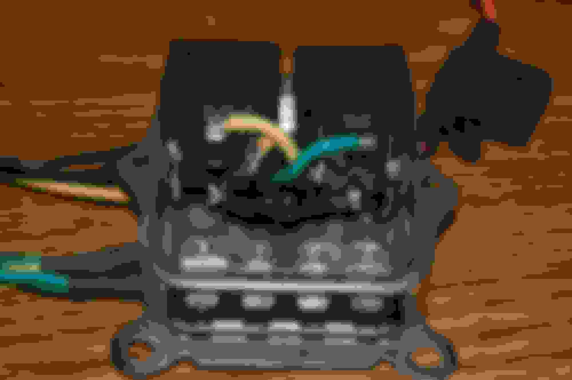
I used two relays and put them in the gutted voltage regulator case. Power comes right from the horn relay just above through the fused wire and goes directly to the headlights. The old headlight wires were extended to meet/close the relays.
BTW, the yellow and green wires are 14 gauge and the orange, fused wire is 12 gauge.
I used two relays and put them in the gutted voltage regulator case. Power comes right from the horn relay just above through the fused wire and goes directly to the headlights. The old headlight wires were extended to meet/close the relays.
That is a good idea for that stock look! I was thinking of putting the relays on front side of the rad support so they can not be seen too easy.
I didn't realize the halogen bulbs draw a little less current I was thinking the other way around. So maybe I'll try some halogens with the stock harness. No corrosion on any connections I rewired the car with electric limited harness back to front about five years ago.
DSR
Here is a link about relays. Designed for car audio guys but works for our application too. Scroll down to the section re wire and fuse calculator. input your loads and it calculates the rest for you
I used the stock wiring on my 61 and, if you get creative with the connectors and know how to crimp, you don't have to butcher any original wiring...
Hi Frank. I think on my 65 I'lI have to separate two of the stock connections that feeds high and low beam from the dimmer switch.. At the connection where the driver side headlight extension plugs into the main harness. There is a jumper wire in the harness side of that connector that runs over to the passenger side headlights. That jumper wire to the passenger side head light and the wire for the driver side light will have to be fed from the relay. This is Doc Rebuilds wiring diagram. I put yellow and green circles on the two connections that would have to be separated. They currently have two wires crimped under one connector in these spots.
I didn't realize the halogen bulbs draw a little less current I was thinking the other way around. So maybe I'll try some halogens with the stock harness. No corrosion on any connections I rewired the car with electric limited harness back to front about five years ago.
When I installed Halogens they made the breaker open and lights blink off and on that tells they drew more current .
 04-20-2017, 06:12 PM