When you click on links to various merchants on this site and make a purchase, this can result in this site earning a commission. Affiliate programs and affiliations include, but are not limited to, the eBay Partner Network.
Could someone please post the wiring diagram for the cooling fan
I've already had the dreaded fan connector burning out a couple of years ago, but it seems like it's something else now.
Thanks in advance.
Can you expand on the actual problem? I might be able to talk you through a couple of tests or pinpoint an issue. If it is interpreting the conditions under which the fans run, it might be a shorter path.
BTW, my favorite place in London is Bag of Nails....or, I mean Bag O Nails.
A couple of years ago I had the "coolant over temp" warning and subsequent "AC off" .. Checked on the forums and indeed it was the middle connector of the plug by the cooling fan that had burnt out. I remade it, all has been fine..... Until..
The other evening I got the same iszsue and was quite stranded. Only it had gotten quite hot and boiled out a fair bit of coolant !!! I had A friend come out drop me some water, wire and tools. I suspected it was the same connector, so I "pieced out" the plug with some heavy duty wire. By this time the engine had cooled and I chanced the drive home. Nearing home I noticed that the temp started to get higher than normal again. I've not had chance to do any real tests and the car is at home in the garage.
So, armed with the wiring diagram I'll hopefully get some time to do some diagnostics.
I am assuming it is a cooling fan issue.
The rather beefy 60a fan fuse is ok.
Am i right in thinking that if I apply 12v to the speed control wire, it should start the fan up at any engine temp ? Thus proving the fan control module good or faulty ?
BTW, my favorite place in London is Bag of Nails....or, I mean Bag O Nails.
Hawksmoor 7 Dials for Sunday Roast....Yum!
Hawksmoor : as good as it it, I think is a bit overrated
Bag O Nails : Not aware of this place but says "Tucked away in the heart of the bustling Soho district, the Bag O'Nails is a private members club offering a luxury experience 'like no other"
A couple of years ago I had the "coolant over temp" warning and subsequent "AC off" .. Checked on the forums and indeed it was the middle connector of the plug by the cooling fan that had burnt out. I remade it, all has been fine..... Until..
The other evening I got the same iszsue and was quite stranded. Only it had gotten quite hot and boiled out a fair bit of coolant !!! I had A friend come out drop me some water, wire and tools. I suspected it was the same connector, so I "pieced out" the plug with some heavy duty wire. By this time the engine had cooled and I chanced the drive home. Nearing home I noticed that the temp started to get higher than normal again. I've not had chance to do any real tests and the car is at home in the garage.
So, armed with the wiring diagram I'll hopefully get some time to do some diagnostics.
I am assuming it is a cooling fan issue.
The rather beefy 60a fan fuse is ok.
Am i right in thinking that if I apply 12v to the speed control wire, it should start the fan up at any engine temp ? Thus proving the fan control module good or faulty ?
If you unplug the connector from the fan control module, the RED is hot all the time. So, in effect, at that connector, you have a +12v supply (black ground, red +12v) and a "line" (Black/Red) all within that connector, two reds, two blacks. Just build two small 8ga or 6ga jumpers with spade terminals on each end. Unplug the connector from the module, jump the two reds, then jump the two blacks. The fans should come on full speed. If not, then the fan is bad. Be aware, there will be a sizable spark when you jumper the black set. That is the first test, the fan.
Hawksmoor : as good as it it, I think is a bit overrated
Bag O Nails : Not aware of this place but says "Tucked away in the heart of the bustling Soho district, the Bag O'Nails is a private members club offering a luxury experience 'like no other"
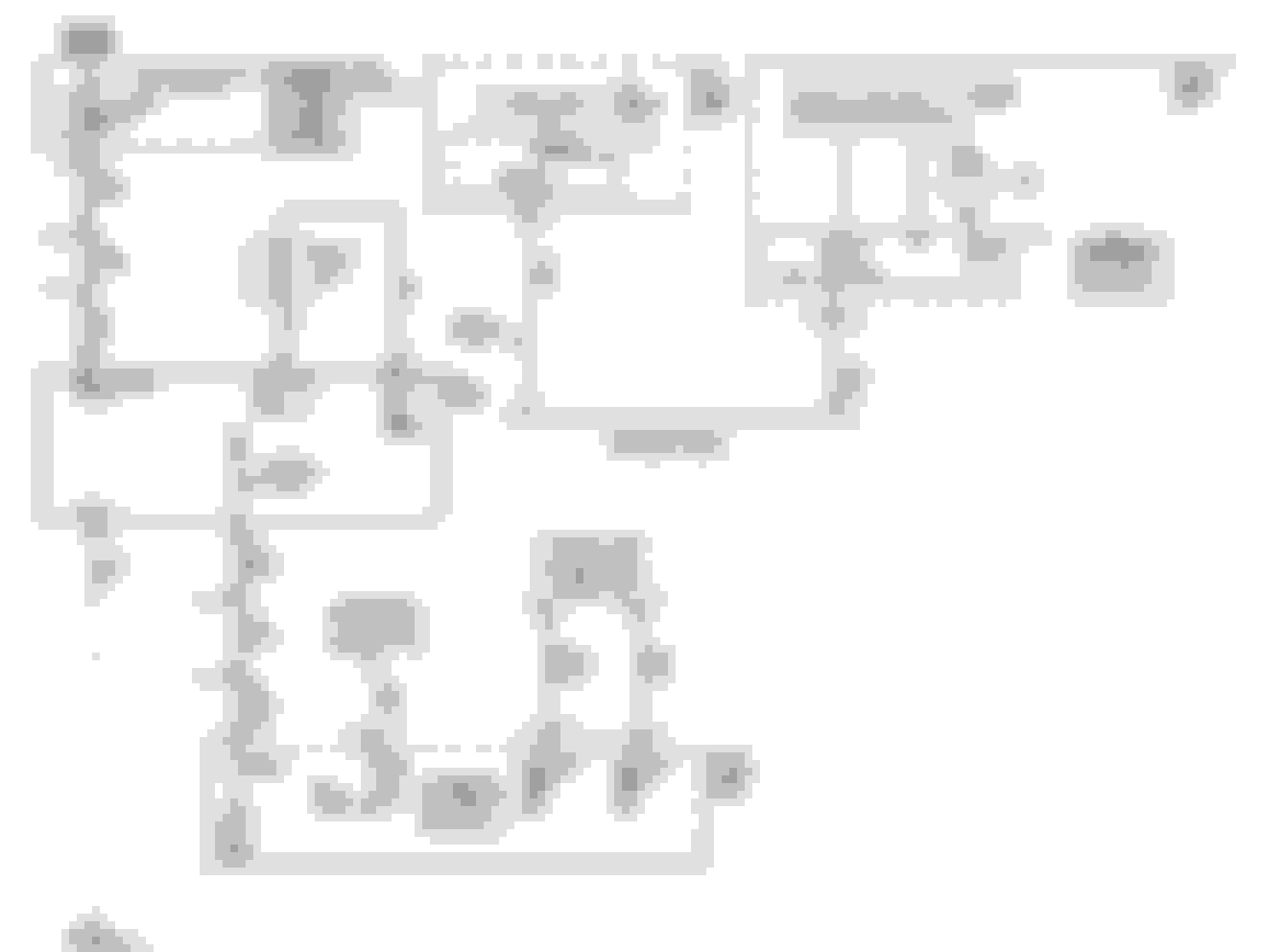
I used spade connectors to piece out the red (+12v) and speed control wires, and a heavy duty block terminal for the black/ground (as it was in a bad way) shown by the yellow links on the diagram
So by connecting the +12v to the smaller red wire going to the fan control module (as shown by the brown link) they should for up at full speed, as you say
Originally Posted by BlindSpot
Your recommendation for Sunday roast? I would be greatly appreciative to you, and will try it on my next trip to London....
I used spade connectors to piece out the red (+12v) and speed control wires, and a heavy duty block terminal for the black/ground (as it was in a bad way) shown by the yellow links on the diagram
So by connecting the +12v to the smaller red wire going to the fan control module (as shown by the brown link) they should for up at full speed, as you say
My mums or course ;-)
No. Separate the smaller ga (18ga) signal wire. It should NOT be jumpered to the large 8 gau red wire, on either side of the fan control module.
The fan control module, essentially, is a large complex relay. It contains +12v and ground at all times. The smaller 18 ga is a signal wire coming directly from the ECM. The ECM sends pulsed, low voltage signals (at infinitely variable frequencies) to the control module which converts those pulses to infinitely variable voltage output to the fan.
If I have your diagram interpretted correctly, you do not want the ECM signal wire directly to either +12v fan line or supply voltage.
Ok, scrap the Brown jumper, I thought that applying 12v the speed control wire would trick the fan control module into switching the fans on, assuming all else is ok. (if it was the case, I would have disconnected the green wire that goes to the ECU as I wouldn't want to put 12v back up it)
However, I thought I read somewhere that there was a test to prove the fan control module but can't seem to find the thread and that was how to do it.
I'll get out to the garage soon (but it's currently 1:20am) and jumper direct to the fan and work back from there - Thanks
P.S. the SoHo Bag O Nails seems interesting ;-)
OK, let me separate into three tests and I'll try to keep it uncomplicated.
To test the fan:
1. Unplug the large connector at the fan control module
2. Jumper the two LARGE ga Reds.
3. Jumper the two LARGE ga Blacks
4. The fan should come on full speed. No ign is necessary, +12v there all the time. If not, replace the fan
To test the Fan control module:
Harness plugged back into the fan control module.
1. Use a needle probe with a wire lead attached to contact the back of the SMALL 18 ga signal wire.
2. Flick the wire end of the probe to ground, with a quick pulse (to simulate an ecm pulse at some random frequency).
3. The fan should come on as something less than full speed which will indicate a good fan control module.
4. If the fan does not run at some speed, the fan control module is bad.
If the first two tests pass, and you still do not have fans coming on and controlled by the ECM, then:
1. Check the signal wire for continuity (a break in the wire) all the way back to the ECM.
2. If bad, repair/replace the signal wire.
3. If good, then check the final earth connection that feeds the fan, It is the ground lug found on the right side upper frame in the engine compartment.
4. If the ground is good and all the tests so far have passed, then you have a failed ECM.
The above instructions are good ones for the tests as described.
From the service manual cooling system secton:
Install appropriately fused jumpers between the cooling fan harness connector terminals 1 and 4 power and ground. The cooling fan should activate at full speed.
You mentioned that you boiled out some coolant. This could indeed inicate that the fan did not start as required.
It could also be a bad thermostat as well.
You also mentioned that once the car cooled down, on the drive home, it started to run hotter than normal.
Did you make sure all the air was out of the cooling system?
Once you determine the fan and speed control modules work or not, and if they do work, look at the thermostat, plugged radiator fins with leaves, and debris, and make sure there is no air in the system.
Since you burnt the connector at the radiator by over driving the fan/having it come on too much, then bank that the problem is one of two now that you have removed that safety link (melted connector).
You either melted the connector to the PWM at the PWM, burnt the PWM up, or since you where over driving the fan too have it running too much, you burnt up the fan motor bearings as well.
Get a 30 amp fuse with wire, put a 30 amp meter in line on it, and a extra ground wire.
Start by spinning the fan by hand, and make sure it freely spins. If it feels like the bearings are binding, or the fan grabby, the ball bearings in the fan are shot.
Next with the wires and meter from about, direct connect the fan after the PWM to the battery. with the fan at full tilt, it should only be drawing 25 amps. If it drawing more then this, its the bearings the problem that caused too much amp draw through the PWM to cause problems.
Next to figure out if the PWM is the problem, tap the fan motor wires out of the PWM, start the car, turn on the A/C and get a reading out of the PWM to the fan motor. Hence you can check the power into the PWM, then back out, and this will tell you if the problem is the power into the PWM or it's connector burnt, or no power out off the PWM with it burn up isntead. Also, as you are checking the wired, make sure that you have a good ground from the PWM connector back to chassis ground.
To bottom line it, you can over drive the fan slightly (have it come on a slightly lower temp) but if you are ramping up the fan to try to hold the engine temp at 180, your wasting your time since the ran and raditor where never designed to do this. So what happens is the fan is being driving 100% of the time, it burns the fan motor bearing up, the fan motor pulls more that it normal 25 amps, and since the PWM is not designed to take this kind of amperage/heat long term, it burns the PWM up.
Bottom line, post your tune temp tables for the raditor fan, but will bank that they are set to bring the raditor fan on way to low; hence time to upgrade to a dewitts radiator, twin fan, and upgraded PWM that handle the kind of heat your going to throw at it long term instead.
It was the fan connector that had gone bad AGAIN and having pieced it out (roadside), I cured the fault. However, in my haste to get it fixed, moving and trying to save any further embarrassment sitting on a main road with the bonnet up, must have shorted the main feed - thus blowing the 60a J fuse !!!! (which I had proven to be ok before blowing it)
Cured one, caused another - all well and good now - my previous repair lasting 2 years, and now permanently soldered jumpers in place !
I Get the issue with the fan and connector now - both times it failed was when the air-con was on - which I believe activates the fan anyway ?
Again, the melted connector was the sign that the radiator fan was being used too much or it bearings starting to go south to cause the motor to pull more amps.
By soldering past the melted connector only, it just moves the problem down to the PWM connector and even the PWM that want to burn up next.
I was under the impression that it was just that one connector that was underrated and liable to fail - but seems like it's potentially the whole poorly designed cooling fan circuit !
I'll meter the current draw and make a decision then.

 07-17-2017, 06:01 PM


 Yes, right on the mark.

