
Is there a guide to assemble the Gauge Cluster and Wiper Switch bezel?
 10-18-2017, 12:52 PM
#1
Racer

Thread Starter
I'm having trouble finding info on this via searching so I thought I'd ask here. I'm struggling to figure out how to reassemble my Wiper Switch bezel and my gauge cluster. I fully took everything apart and restored every bit, but I made the mistake of loosing the assembly photos I took, so I'm a little lost.
Any ideas?
The car is a 1975 with A/C and the wiper switch bezel is the one that's lit
Any ideas?
The car is a 1975 with A/C and the wiper switch bezel is the one that's lit
Last edited by Shdggsdv; 10-18-2017 at 12:52 PM.
 10-18-2017, 02:09 PM
#2
Team Owner

Member Since: Sep 2006
Location: Westminster Maryland
Posts: 30,173
Likes: 0
Received 2,878 Likes
on
2,515 Posts

Hi sd,
It's easiest to install the center bezel with the right side lower dash panel removed.
Put the radio in position, but don't put the 2 nuts on the seems yet.
Then the center gauge bezel can be put into place. Check the function of all the gauges and lights. Having the right side dash panel off allows good access to the back-side of the gauge cluster.
Then the wiper switch can be connected and the bezel slipped into place. 3 screws.
If everything is working put the right side dash panel in place.
Good Luck!
Regards,
Alan
The following users liked this post:
Jeffs82c3 (10-18-2017)
10-19-2017, 11:34 AM
#3
Racer
Thread Starter
Hi sd,
It's easiest to install the center bezel with the right side lower dash panel removed.
Put the radio in position, but don't put the 2 nuts on the seems yet.
Then the center gauge bezel can be put into place. Check the function of all the gauges and lights. Having the right side dash panel off allows good access to the back-side of the gauge cluster.
Then the wiper switch can be connected and the bezel slipped into place. 3 screws.
If everything is working put the right side dash panel in place.
Good Luck!
Regards,
Alan
It's easiest to install the center bezel with the right side lower dash panel removed.
Put the radio in position, but don't put the 2 nuts on the seems yet.
Then the center gauge bezel can be put into place. Check the function of all the gauges and lights. Having the right side dash panel off allows good access to the back-side of the gauge cluster.
Then the wiper switch can be connected and the bezel slipped into place. 3 screws.
If everything is working put the right side dash panel in place.
Good Luck!
Regards,
Alan
Last edited by Shdggsdv; 10-19-2017 at 11:35 AM.
10-19-2017, 12:20 PM
#4
Le Mans Master


I'm having trouble finding info on this via searching so I thought I'd ask here. I'm struggling to figure out how to reassemble my Wiper Switch bezel and my gauge cluster. I fully took everything apart and restored every bit, but I made the mistake of loosing the assembly photos I took, so I'm a little lost.
Any ideas?
The car is a 1975 with A/C and the wiper switch bezel is the one that's lit
Any ideas?
The car is a 1975 with A/C and the wiper switch bezel is the one that's lit
 10-19-2017, 01:30 PM
#5
Team Owner
Member Since: Sep 2006
Location: Westminster Maryland
Posts: 30,173
Likes: 0
Received 2,878 Likes
on
2,515 Posts
Hi S,
Here's the diagram from the Keen site that cg mentioned.
Does this show what you're looking for?
The Assembly Instruction Manual doesn't show the sequence of assembly for the center gauge cluster because it came to the production line as an assembly.
The AIM only shows the cluster assembly being installed in the dash opening for it.
Regards,
Alan
The following users liked this post:
Bruce schultz (06-13-2019)
10-19-2017, 03:39 PM
#6
Former Vendor
Member Since: Aug 2006
Location: Jeffersonville Indiana 812-288-7103
Posts: 76,656
Received 1,813 Likes
on
1,458 Posts
St. Jude Donor '08-'09-'10-'11-'12-'13-'14-'15
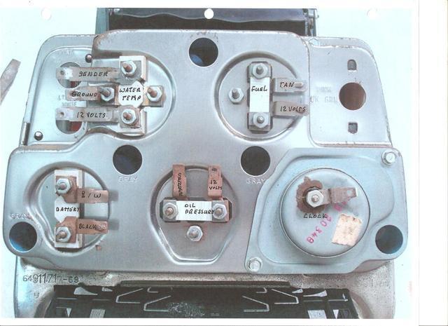
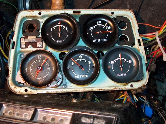
To my knowledge, GM never used a lens gasket as shown in the picture above. GM used lens bumpers that were about 1/2" long and sat in the dash bezel (there will be hash marks where they belong), then the lens went in place, then the small lenses for the seat belt, brake etc.. then the retainer, then the lens filter spacers (white), then the filter gaskets.. The gauges mounted to the "can" or pod, and once installed you place the pod over top of the mix of parts listed above. The pictures below will show you how to assemble each gauge in the gauge pod.
This will help you assemble the gauges to the back of the housing.


This will help you assemble the gauges to the back of the housing.
Last edited by Willcox Corvette; 10-19-2017 at 03:46 PM.
10-19-2017, 03:51 PM
#7
Team Owner
Member Since: Sep 2006
Location: Westminster Maryland
Posts: 30,173
Likes: 0
Received 2,878 Likes
on
2,515 Posts
Hi W,
VERY nice!
Is there a photo showing the entire cluster housing from the rear side with the gauges and connectors in place?
That would be nice.
Regards,
Alan
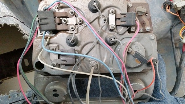
I have one but it may not be quite complete, and, I don't know what year it is. Note the difference in the oil pressure gauge connection.
The pictures might even have been stolen from you?!?
VERY nice!
Is there a photo showing the entire cluster housing from the rear side with the gauges and connectors in place?
That would be nice.
Regards,
Alan
I have one but it may not be quite complete, and, I don't know what year it is. Note the difference in the oil pressure gauge connection.
The pictures might even have been stolen from you?!?
Last edited by Alan 71; 10-19-2017 at 03:57 PM.
10-19-2017, 06:05 PM
#8
Former Vendor
Member Since: Aug 2006
Location: Jeffersonville Indiana 812-288-7103
Posts: 76,656
Received 1,813 Likes
on
1,458 Posts
St. Jude Donor '08-'09-'10-'11-'12-'13-'14-'15
Hi Alan-
What a pain it was doing those... but I had fun. I kept getting so many emails and questions about how to assemble the individual gauges that I took a cluster apart one gauge at a time and did a photo shoot..
I don't know if it's mine or not.. that's horrible.. I have sometimers.. lol. But there are 30k pictures on my site so it's hard sometimes to keep up with them. It doesn't look like one of mine because usually I'll slap a WCD or Willcox on my pictures, sometimes I get in a hurry and forget.
The lower picture you posted is from a earlier car with a mechanical oil pressure gauge, the top picture you posted if from a 1975-1976 cluster.
Here are the pics that I have found on the tech site for 1968-1974 cars
Last edited by Willcox Corvette; 10-19-2017 at 06:08 PM.
10-19-2017, 06:10 PM
#9
Race Director


I AGREE with Will =***. T=I have also never seen a gasket like what was shown in the illustration that goes between the main housing and the lens. BUT...what I have seen every time is that there is a somewhat dense foam rubber round material that fits into the special areas that are cast into the bezel so the lens does not make noise and vibrate when fully installed.
The area for the foam material run vertically and will be in between the gauges and on the outer portion of some of them. Take a look and you will see an area when a piece about an inch long would fit. Tried to find a photo on the internet and could not.
DUB
The area for the foam material run vertically and will be in between the gauges and on the outer portion of some of them. Take a look and you will see an area when a piece about an inch long would fit. Tried to find a photo on the internet and could not.
DUB
10-19-2017, 06:13 PM
#10
Former Vendor
Member Since: Aug 2006
Location: Jeffersonville Indiana 812-288-7103
Posts: 76,656
Received 1,813 Likes
on
1,458 Posts
St. Jude Donor '08-'09-'10-'11-'12-'13-'14-'15
I AGREE with Will =***. T=I have also never seen a gasket like what was shown in the illustration that goes between the main housing and the lens. BUT...what I have seen every time is that there is a somewhat dense foam rubber round material that fits into the special areas that are cast into the bezel so the lens does not make noise and vibrate when fully installed.
The area for the foam material run vertically and will be in between the gauges and on the outer portion of some of them. Take a look and you will see an area when a piece about an inch long would fit. Tried to find a photo on the internet and could not.
DUB
The area for the foam material run vertically and will be in between the gauges and on the outer portion of some of them. Take a look and you will see an area when a piece about an inch long would fit. Tried to find a photo on the internet and could not.
DUB

They are just rattle pads.. this is another case of someone making a part that didn't exist or just a diagram error. Tom's a good guy so I'd bet it was just an error. lol..
The rattle pads can be made from 1/16" foam rubber you can get at your local hobby shop too.. you can usually buy a foot of this for pennies.
Ernie

 10-21-2017, 07:17 AM
#12
Team Owner
Member Since: Sep 2006
Location: Westminster Maryland
Posts: 30,173
Likes: 0
Received 2,878 Likes
on
2,515 Posts
Hi,
Nice photo 'q'!
Rarely SEE those pads!!
My 71 cluster has the little pads shown in q's photo.
I imagine a lot of these end up on the floor if the cluster is taken a part in the garage, and then disappear. (sort of like the little black plastic tubes on the fiber-optic connections on the headlights.)
Regards,
Alan
MAY I save your photo?
10-21-2017, 07:36 AM
#13
Burning Brakes

Hi,
Nice photo 'q'!
Rarely SEE those pads!!
My 71 cluster has the little pads shown in q's photo.
I imagine a lot of these end up on the floor if the cluster is taken a part in the garage, and then disappear. (sort of like the little black plastic tubes on the fiber-optic connections on the headlights.)
Regards,
Alan
MAY I save your photo?
Nice photo 'q'!
Rarely SEE those pads!!
My 71 cluster has the little pads shown in q's photo.
I imagine a lot of these end up on the floor if the cluster is taken a part in the garage, and then disappear. (sort of like the little black plastic tubes on the fiber-optic connections on the headlights.)
Regards,
Alan
MAY I save your photo?
 10-22-2017, 08:25 PM
#14
Racer
Thread Starter
Hi S,
Here's the diagram from the Keen site that cg mentioned.
Does this show what you're looking for?
The Assembly Instruction Manual doesn't show the sequence of assembly for the center gauge cluster because it came to the production line as an assembly.
The AIM only shows the cluster assembly being installed in the dash opening for it.
Regards,
Alan
Last edited by Shdggsdv; 10-22-2017 at 10:07 PM.
 10-23-2017, 10:02 AM
#16
Team Owner
Member Since: Sep 2006
Location: Westminster Maryland
Posts: 30,173
Likes: 0
Received 2,878 Likes
on
2,515 Posts
Hi S,
I'm thinking you're asking about the seat belt indicator for your 75?
I'm not familiar with later cars.
I'm pretty sure Willcox has done some work on parts for the seat belt warning.
Why don't you call them to see just what you'll need and what parts they may offer.
Sorry I can't actually help.
Regards,
Alan
This is the set up for 69. I don't know if it shows anything that may help you or not.
Last edited by Alan 71; 10-23-2017 at 10:14 AM.


 10-23-2017, 12:07 PM
#18
Team Owner
Member Since: Sep 2006
Location: Westminster Maryland
Posts: 30,173
Likes: 0
Received 2,878 Likes
on
2,515 Posts
Hi,
I guess the pictures that CG posted of a later bezel shows the earlier/later difference in that corner of the bezel.
Later cars no longer have the push-button mechanism to turn off the seat belt reminder indicator that the Earlier cars did.
The earlier reminder re-set each time the car was started and didn't have anything to do with the actual fastening of the belts.
Regards,
Alan
Last edited by Alan 71; 10-25-2017 at 06:22 AM.
10-24-2017, 11:57 PM
#19
Racer
It seems to me the most recent request is asking for a picture on how to hook up the wires to the various gauges... and it also seems to me that based on the pictures of the gauges and my own experience of pulling this cluster many times, the good general idiot proofed these connections so that each plug will only attach to the correct terminal.
Also a shout out to Willcox for the excellent photo's and walk through. That is customer service there!
Also a shout out to Willcox for the excellent photo's and walk through. That is customer service there!

