TPS Voltageweirdness
#1
Burning Brakes


Thread Starter
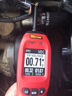
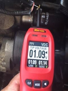
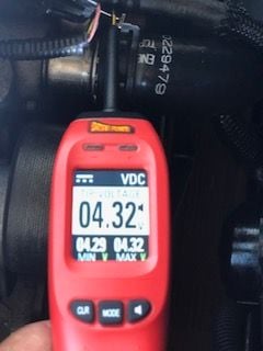
I am in the process of hooking up my NX Express Window Switch. I used the white wire from the ECU in the passenger fender/footwell. When I did my setup with the engine not running and pedal to the floor I am only seeing 2.5v from TPS white wire. Idle shows 0.5v. Is this normal? Shouldn't it be 5.0v?
#2
Moderator, Tech Contributor

Member Since: Sep 2013
Location: Cape Coral, Florida
Posts: 9,518
Received 2,122 Likes
on
1,687 Posts

Shouldn't your post be in the C4 Forum ???...says you have a '91 !!
#3
Tech Contributor

Member Since: Dec 1999
Location: Anthony TX
Posts: 32,736
Received 2,180 Likes
on
1,583 Posts
CI 6,7,8,9,11 Vet
St. Jude Donor '08

There are TWO variable resistors in the TPS. Each is reversely proportional to the other
Each resistor has three wires. 5 VDC Ref, TP Sensor signal and a LOW Ref.
One resistor 5 VDC Ref is DK Green, TP Sensor Sig is DK Blue and the Low Ref is PPL
The other resistor is 5 VDC Ref yel/black stripe, TP Sensor Sig is Pink and the Low Ref is White
Your are on the LOW ref (Circuit ground)
Bill
#4
Burning Brakes


Thread Starter
#5
Burning Brakes


Thread Starter
There are TWO variable resistors in the TPS. Each is reversely proportional to the other
Each resistor has three wires. 5 VDC Ref, TP Sensor signal and a LOW Ref.
One resistor 5 VDC Ref is DK Green, TP Sensor Sig is DK Blue and the Low Ref is PPL
The other resistor is 5 VDC Ref yel/black stripe, TP Sensor Sig is Pink and the Low Ref is White
Your are on the LOW ref (Circuit ground)
Bill
Each resistor has three wires. 5 VDC Ref, TP Sensor signal and a LOW Ref.
One resistor 5 VDC Ref is DK Green, TP Sensor Sig is DK Blue and the Low Ref is PPL
The other resistor is 5 VDC Ref yel/black stripe, TP Sensor Sig is Pink and the Low Ref is White
Your are on the LOW ref (Circuit ground)
Bill
#6
Burning Brakes


Thread Starter
I have not done anything like this. I am working to hook up a NX Express window switch.
#7
Moderator, Tech Contributor

Member Since: Sep 2013
Location: Cape Coral, Florida
Posts: 9,518
Received 2,122 Likes
on
1,687 Posts

That's the BCM !!!....TPS is on the throttle body !!...you are definitely in the wrong area Dude !!
Last edited by C5 Diag; 10-18-2018 at 02:29 PM.
#8
Burning Brakes


Thread Starter
#9
Moderator, Tech Contributor

Member Since: Sep 2013
Location: Cape Coral, Florida
Posts: 9,518
Received 2,122 Likes
on
1,687 Posts

First you said "FOOTWELL"...yes, the PCM is inside the passenger side "FENDERWELL" !!...I trust you Bro...with this window switch you are trying to install why are you testing the TPS Sensor ???????
Last edited by C5 Diag; 10-18-2018 at 04:09 PM.
#10
Burning Brakes


Thread Starter
So I tapped into the White wire that goes to the PCM in the fenderwell. It it definitely tied to the TPS as it goes up and down voltage as I move the pedal. It maxes out at 2.5v which I was expecting 5.0v. Is getting only 2.5v max out of the white wire normal?
#11
Tech Contributor

Member Since: Dec 1999
Location: Anthony TX
Posts: 32,736
Received 2,180 Likes
on
1,583 Posts
CI 6,7,8,9,11 Vet
St. Jude Donor '08

The white wire is a ground ref. Dont know what the needs of the window switch is but I would suspect it is looking for the actual TS signal circuit voltage
#12
Moderator, Tech Contributor

Member Since: Sep 2013
Location: Cape Coral, Florida
Posts: 9,518
Received 2,122 Likes
on
1,687 Posts

Why are you checking TPS signal voltage at the PCM ????...you do it at the TPS sensor which is on the right hand side of the throttle body...it has 6 wires...the dark blue and the pink wires are your signal wires...the white wire is a "low reference" (ground) and it goes from the TPS to the TAC Module...whatever you are doing are you tapped into the TAC Module pin #10??...that's not the PCM my friend...I think you will have problems hooking up this NX Express window switch there...sorry but I can't help you any further...if I were you I have this thing professionally installed. I don't want to see you frying your TAC Module or PCM !!...good luck !!!
#13
Burning Brakes


Thread Starter
Why are you checking TPS signal voltage at the PCM ????...you do it at the TPS sensor which is on the right hand side of the throttle body...it has 6 wires...the dark blue and the pink wires are your signal wires...the white wire is a "low reference" (ground) and it goes from the TPS to the TAC Module...whatever you are doing are you tapped into the TAC Module pin #10??...that's not the PCM my friend...I think you will have problems hooking up this NX Express window switch there...sorry but I can't help you any further...if I were you I have this thing professionally installed. I don't want to see you frying your TAC Module or PCM !!...good luck !!!
I made a mistake in my writing in the previous posts.


