When you click on links to various merchants on this site and make a purchase, this can result in this site earning a commission. Affiliate programs and affiliations include, but are not limited to, the eBay Partner Network.
Autometer Gauges, probably will need help with install
I just purchased all new autometer Cobalt series gauges for my '76, as my big Christmas gift! Some of the original gauges worked, some didn't, troubleshooting most of them seem to yield little results, so since i'm planning a restomod, I went with all new autometer Cobalt series 52mm gauges. Replacing my fuel, volts, oil press., temp, and the clock with a narrowband Air/Fuel to help with tuning. I also got the 5inch 1000 rpm tach and the GPS speedometer. Can't wait to refit my dash will all new backlit modern gauges. I am sure I'll need a hand figuring out what wire to tap into, as well as if anyone has an idea on a good location to mount the GPS receiver out of site (they recommend roof, dash, or rear deck) but i would like to keep it out of sight the best I can, as I understand it, the fiberglass will provide very little interference, unlike most metal body cars, so is in the engine bay or fender a possibility? install photos and results soon to follow, as hopefully I'll have some time to get these complete over the holiday break.
I am doing all this now but I doubt you want to go the way I'm doing it. As for the GPS receiver I have mine on the Cobra under the fiberglass and it works without any issue. On a rare occasion it gets lost for a second probably due more to trees or other things in the way. On the Vette I did mount it on the dash but it is on the passenger side tucked so far in you will not see it unless you are really looking for it.
As for the wiring I bought a new interior harness and have gutted about 1/4 of the wiring out of it. I am wiring the speedo head, the tachometer and the console gauges with separate 6 prong plugs. This way I can just plug in or unplug if I need to service it. I did individual wires before and what a PIA to unplug all those wires. For the gauges I would daisy link the power and the grounds so yo uonly have one connection for each of them. This simplifies putting power to each gauge wit ha separate wire. Do the same with the gauge light power and grounds. It makes for a neater and easier system. The sender wires you just have to get the correct one to the correct gauge. Get yourself a good wiring diagram if you don't have one. Guessing will only get you burnt wires or inop gauges.
BTW I solder every butt connection and put shrink tube on it. Those butt connectors have a tendancy to work out and the connection is not great. Much more time consuming but well worth the piece of mind. I have plenty of pictures if yo uneed them and can take more since my gauges are all out and the wiring harness is also out. I am waiting for more 6 prong connectors at the moment.
I originally did not have the turn signal indicators but have incorporated them into the heads just below the gauges. Small LED green lights.
Gordon, I was planning on doing the same for the turn signals, including some LED's on the housing for the signals as well as the brights indicator. I would appreciate any reference photos you can provide. I plan on going through the wiring, and will be soldering the connections as well. Where did you get the plugs for the gauges? That is something I would love to include. As for the common power/ground, since i pulled out the factory air conditioner system (with the hopes of someday going with vintage Air) that frees up some space under the hood where i had planned to put a new fuse panel, with the more modern blade fuses and ease of access than the glass ones under the driver side. Since i will be pulling the dash out once again to fit all these new gauges, I can also place the common ground and power locations on the firewall back there, and clean up the area behind the dash. I don't mind doing the work (what else is a project car for) or spending the time to ensure its right. It sounds like you've already done what I hope to accomplish, some reference photos would be invaluable. Thanks!
If i were to put a buss bar for the ground on the behind the center console and gauges and wire the grounds for the new gauges to that, would it be feasible to use the existing grey power wires for the current gauge lamps that come one when the headlight switch is pulled, as a 12v power source for the new gauge illumination?
If i were to put a buss bar for the ground on the behind the center console and gauges and wire the grounds for the new gauges to that, would it be feasible to use the existing grey power wires for the current gauge lamps that come one when the headlight switch is pulled, as a 12v power source for the new gauge illumination?
What I did since the gauge lights draw very little power is again daisy link the 5 12v+ white wires together and the grounds together and hooked them to one gray wire for the 12v+ to light the gauges. The grounds can be routed to one of the black ground wires for the console. This way I did not have 5 individual wires. I'll take a picture of the back of my gauge cluster. I kind of stepped down so I did not have all 5 together. That makes a big ball of wire.
I put a buss bar outside on the passenger side down low. I ran a heavy gauge wire from the starter lug to the buss bar. i run my 2 electric fans, the Vintage Air system and the computer from this buss bar. I just also hooked up my electric headlight motors to this. I think I ran a #6 gauge wire. I also ran a seperate #8 from the alternator down to this so there is plenty of power down there. I'll get some pictures up.
The 6 wire terminals that I used are actually for a trailer. I found them on the internet and they have 12 inch pigtails so putting them in is easy. I only bought one to test it out. It works well so I ordered 3 more. They are like 7 bucks a piece.
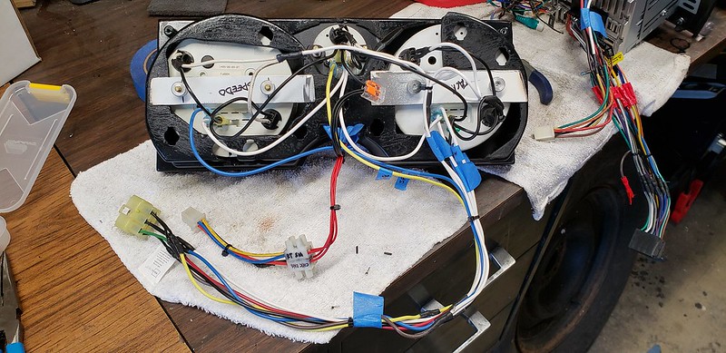
Here is a picture of the back of the speedo head. There is 6 wires but I only used 5 so the green is empty. You could use that for the high beam or something. I put an LED on the console where the clock stub is and that is my high beam indicator. You can see the plug on the end. That is a female and on the wiring harness is the male end.
Gordon. Great, Thanks for the photos, that is how i was thinking of doing the Buss, but the idea for a trailer terminal plug is excellent, I will certainly look into it!
Here is two more of the main harness. You can see the 6 wire terminal where the speedo head would be. A little further over towards the left are the wires bundled ready for the terminal on the tach side. You then have the wiper switch with blue wires (stock) then the next bundle will be the console gauges. What you can’t see is the sender wires which are in the car and will be put in the harness once this is in the car. A little further down is the stock radio wires which I have an aftermarket setup that will be included. There is als oa loan pink wire there which will be the 12v+ ignition wire for the VA system. The heavy wires are already run for the VA system.
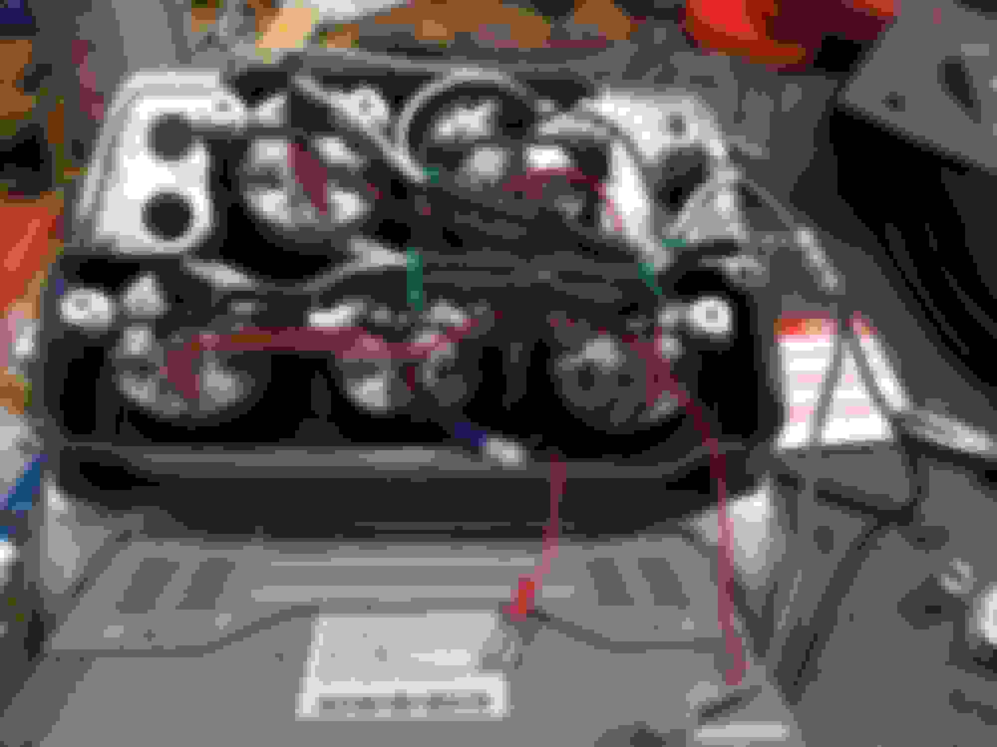
Just for reference here is the VA system and some of the other wires coming from the engine compartment are the sender wires. The big heavy yellow one is the fuel pump lead.
Great thread. I love the idea of the trailer plugs. Tried making my own molex plugs but not really 100% happy with the ones I made...must be cheapo ones. Will be watching for the 5" speedo and tach installs. I put Autometer in my restomod but made a new facplace and cut out the old one in the center of the dash so I could get 6 gauges in it. Keep up the good work.
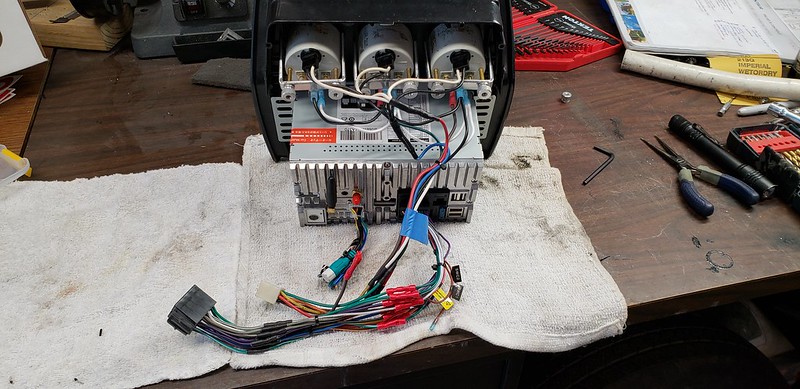
Forgot this one. As you can see I stepped down the 5 wires to 2 then one on the lights and ground. No sender wires here but you can see the daisy link for the power and ground on the gauges. Also grounded the metal base for the wipers. The right hand gray and black wires are for the check engine light. I used the front plastic piece from an 82 in that port. The wiring for the LS3 is you put power to it and what makes the light come on is the computer grounds it. So one wire is just ign 12+ the other wire goes to the computer. I removed the head lamps light as with electric ones I know they are up. The little red wire hanging down low is the LED in the clock adjuster hole. That will be my high beam indicator.
Forgot this one. As you can see I stepped down the 5 wires to 2 then one on the lights and ground. No sender wires here but you can see the daisy link for the power and ground on the gauges. Also grounded the metal base for the wipers. The right hand gray and black wires are for the check engine light. I used the front plastic piece from an 82 in that port. The wiring for the LS3 is you put power to it and what makes the light come on is the computer grounds it. So one wire is just ign 12+ the other wire goes to the computer. I removed the head lamps light as with electric ones I know they are up. The little red wire hanging down low is the LED in the clock adjuster hole. That will be my high beam indicator.
This modification does take some time and thinking.
Looking good Gordonm.
Last edited by Street Rat; 12-19-2018 at 07:51 AM.
Gordon, Thanks for the photos, this helps a lot. I was wondering what to put in the hole for the clock adjuster, I do like the idea of having an LED located there for the high beams, i might just have to steal that idea from you. Thanks!
I also want to commend your choice of insulation, i too am running the "Cool-it" over entire interior of my car. I was missing the dash, so that will be done as i work on this mod as well.
Last edited by RocketNerd; 12-19-2018 at 08:25 AM.
Reason: added a thanks
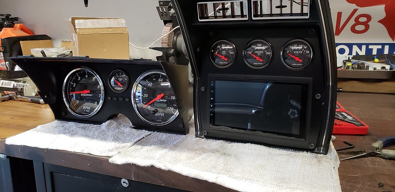
Here is the console gauges all lite up. I just hooked up battery power to the gauges and lights. No sender wires that is why most gauges are pegged. You can see the check engine light and the really bright orange one in the clock adjuster hole will be for the high beams. Might have to change it out for a little less bright. Might be blinding at night.
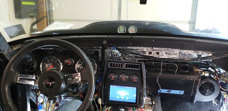
Here's my setup. I have a 79 but incorporated a screen with it. The turn signals, brights and check engine light are actually proper indicators with symbols. I dug around on Ebay for them from China. My last design for speedo/ tach i used plexiglass and was able to reuse the factory indication lens and locations.
i used plug and play thought also for easy removal. Amazon is useful for the multi pin connectors or pig tails. Do yourself a favor a solder your connections.
. Might have to change it out for a little less bright. Might be blinding at night.
You may try some led bulbs. These are autometer blue led bulbs. You have many different colors and brightness on the led bulbs to cater to your liking.

 12-18-2018, 11:43 AM