When you click on links to various merchants on this site and make a purchase, this can result in this site earning a commission. Affiliate programs and affiliations include, but are not limited to, the eBay Partner Network.
I bought a replacement voltage regulator for my 65 Vette (327 c.i., 300 hp, air). While putting it in, one of the wires broke off at the car end, and I can't find where it goes. The regulator has a 4-wire plug on one side and a 1-wire plug on another side. The wire from the 1-wire plug broke off at the end that attaches to the car. Can anyone tell me exactly where that wire goes?
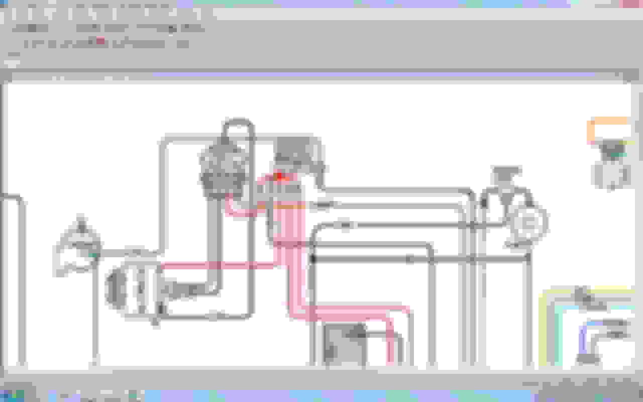
A picture or color of the wire would be nice, however there is no one wire plug. There is a single black wire mounted under a screw on the case of the regulator that attaches to the case of the alternator for a ground. On my 65 a/c car that black wire also ties to the mounting bolt of the horn relay for a ground. I don't know for sure if that was only for an a/c car, but the ground won't hurt if it's connected to both the alternator and the horn relay case.
Thank you for the replies. I had looked at the wiring diagram in Shop Manual (the same diagram you posted in the reply) and saw the single wire going to the alternator ground, but I was uncertain because the wire was too short to go there and actually went somewhere near the regulator or the horn relay. As you have noted, it actually goes to the horn relay mounting bolt. That was what I suspected, but I did not want to ground the wire if I was wrong. Also, that single-wire connection is directly connected to one of the contacts in the 4-wire plug but is not directly connected to the case of the regulator. There is 23 ohms resistance between that connection and the case of the regulator. The new regulator has 4k ohms resistance between that single-wire connector and the case.
The wire is black, and I had not posted a photo because I did not know how to post a photo.
The old regulator is the original electromechanical regulator, and I was replacing it with a new electronic one. The various Corvette sites (Corvette Central, Corvette America, Zip-Corvette, etc) offer an electronic conversion for about $45, but you have to take apart your original regulator and make a lot of modifications to the internals to take the new electronics. I found an electronic regulator that is a direct replacement, is the same size and shape, and can even take the original cover if you drill out the two rivets that hold the cover on the new one. It is Standard Motor Products VR103T Voltage Regulator, $23 on Amazon (Item B004BTKZQ0). There are a couple of other similar ones there. I picked this one because of the relevant reviews and good reviews in general for Standard Motor Products items. And since it does not require cannibalizing my old regulator, I still have the old one in case the electronic one does not work or dies.
And I have partially figured out how to post photos. This is the bottom of the original regulator. The 4-wire connector is under the frame at the right and the single-wire connector is at the bottom. I could not get two photos in this post, so I will put the picture of the new regulator in another post.
Here is the picture of the bottom of the new electronic regulator. It has the connectors on it because once on, they do not want to come off.
Note that the 4-wire connector is keyed to fit only one way, although it is possible to put it on backwards without too much force.
Thanks again for the help. You are an invaluable resource.
David
I haven't had one with that connector. Mine have used a ring terminal under one of the cap screws or in a separate screw in one of the holes on the base. Either way it's ground and the horn relay is grounded at the radiator support where all the black wires come up from the headlights. You should be good to go by connecting it to the horn relay mount.
That single wire spade connector is for the radio noise suppression capacitor; its not a ground..
It mounts on top of the V/R
Yes--that's it!. I just looked at the capacitor mounted below the horn relay, and it's lead wire is gone.
That explains why the 1-wire spade connector is not connected to the case of the regulator.
Thank you!
If its an original capacitor it no doubt has long since died - many just epoxy the lead wire back in to the top of the capacitor and remount the component just to keep the original look and it hurts nothing..
If its an original capacitor it no doubt has long since died - many just epoxy the lead wire back in to the top of the capacitor and remount the component just to keep the original look and it hurts nothing..
What got me into this was replacing the original electromechanical voltage regulator with a solid state regulator. I think the solid state ones do not throw off nearly as much radio noise since they do not have sparks across points in the regulator, so the capacitor probably will not make much difference.
What got me into this was replacing the original electromechanical voltage regulator with a solid state regulator. I think the solid state ones do not throw off nearly as much radio noise since they do not have sparks across points in the regulator, so the capacitor probably will not make much difference.
That's a fact. It is difficult to argue that a mechanical regulator is in any way superior to a good solid state substitute beyond considerations of appearance or purity. Electronic regulators are so fast that they eliminate flicker and reduce flare in headlamps. And, as you point out they eliminate the functional need for the interference condenser. Keep in mind that only the original Delco radio AM bands needed the condensers. Later aftermarket radios typically don't need it, but then again they can't pull in AM radio anywhere near as well as the originals.
You will hear from some, who have never had a car judged, that judges can detect the conversion due to the way the solid-state V/Rs operate...they didn't detect mine in regional judging. Basically, the repros are crap - most are non-adjustable, NOS versions are becoming rare and expensive and the folks that restore originals are rapidly giving up the work...
We'll see more and more conversions of V/Rs, radios and ignition systems as time progresses - I have no doubt. I converted my own undetectably but there are folks that will do it for you as well... My home-brew Wells VR-715 conversion is going on 4 years now without a single issue.
My original Delco VR has its cover held on with screws through the flares in the side ledges (see post #4), and the Standard Motor Products VR103T uses rivets in the same ledge locations (see post #5). The picture of the Wells VR-715 on Amazon (Item B000C994RO) shows its cover is held on with a screw through the center of the cover. The photo of your Wells (post #7) looks like it could not have had such a center screw, as there are components on the circuit board there, so Wells must have changed the physical design in the 4 years since you got yours. That means putting an original Delco cover on the SMP would be easier than on the Wells.
...and the folks that restore originals are rapidly giving up the work...
I do not believe anyone anywhere has restored the electrical operation of a mechanical voltage regulator; it would be tantamount to fixing a burned out bulb. No one would bother to re-wind an open coil if they could, and the contacts can only be cleaned up. In the old days we might have gotten away with that once or twice before a new regulator was installed. My recollection is that voltage regulators were pretty much considered consumable items like brake pads and belts.
I'm reasonably sure a "restored" regulator was mostly cosmetic. I presume contacts were cleaned up and maybe adjusted though adjusting a mechanical regulator is done on the car, connected to the generator/alternator it regulates. But an old regulator is old even if it looks new. The new electronic board under the lid of an original housing as Frank did and describes is the way to go in the absence of a good functioning original.
Dan
I can't say what was done, IIRC John Pirkle was the guy doing them, as Mssr. Wolf does when restoring original fuel senders I'm sure he retained as much of the original parts as possible. Any restorer I know will declare a component DOA if its beyond economical or practical sense to mess with it...or the end result will be unreliable.
Last edited by Frankie the Fink; 02-15-2019 at 10:02 AM.
My original Delco VR has its cover held on with screws through the flares in the side ledges (see post #4), and the Standard Motor Products VR103T uses rivets in the same ledge locations (see post #5). The picture of the Wells VR-715 on Amazon (Item B000C994RO) shows its cover is held on with a screw through the center of the cover. The photo of your Wells (post #7) looks like it could not have had such a center screw, as there are components on the circuit board there, so Wells must have changed the physical design in the 4 years since you got yours. That means putting an original Delco cover on the SMP would be easier than on the Wells.
The Wells VR-714 picture from Amazon:
Can't say with certainty on the lid screw location (not sure why it matters) - here is the base of the unit I bought 4 years ago and if this is what the top screw threads into then indeed, it was off center back then...
Last edited by Frankie the Fink; 02-15-2019 at 10:07 AM.
You can TIG repair the points, it’s done in aviation all the time to repair ignition vibrators / boosters. I replaced my VR with a solid state unit 18 yrs ago, and the original cover fit perfect.
That photo of the bottom of your Wells VR when it was new (post #18) does not have holes in the side flares. Your photo of how it looks now (post #7), does have holes there to screw on an original cover (see post # 4), so drilling those holes must have been part of your conversion.
But these photos show that even with an original cover, there is a noticeable external difference between an original Delco and either the Wells or the SMP: the Delco has the single spade for the radio noise suppression capacitor offset further from the middle of the side.
On the original Delco, the end of the spade is 1/4" wide, with its center 1/2" from the center of the screw (3/8" between the edge of the spade and the center of the screw).
On my new SMP, and also on your Wells, judging from your photos, the end of the spade is 1/4" wide, with its center 1/4" from the center of the cover screw (1/8" between the edge of the spade and the center of the screw).
That means the spade has been moved 1/4". With everything assembled on the car, that change is easily noticed because the edge of the connector will be 1/4" from the center of the screw with the Delco but aligned with the center of the cover screw with the SMP or Wells.
Here are photos of the bottoms of the Delco and the SMP:
 02-13-2019, 07:44 PM