UPDATED Again 8/25/13**** Ultimate DIY/FAQ Thread ...It's All in HERE!!
 02-07-2012, 08:07 AM
#121
Tech Contributor

Fast 92 intake with LS2 Throttle Body install
Its on my web page too... www.ToqueZ06.com
forums.corvetteforum.com/c5-tech/2980350-procedure-fast-92-intake-and-ls2-throttle-body-install-c5-corvette.html
Its on my web page too... www.ToqueZ06.com
forums.corvetteforum.com/c5-tech/2980350-procedure-fast-92-intake-and-ls2-throttle-body-install-c5-corvette.html


 03-24-2012, 07:04 AM
#124
Team Owner


Thread Starter
03-24-2012, 07:06 AM
#125
Team Owner
Thread Starter
04-24-2012, 04:29 PM
#127
Tech Contributor
Guys:
Something I had wanted to do for a while now... Just managed to remember when I was changing my oil today...
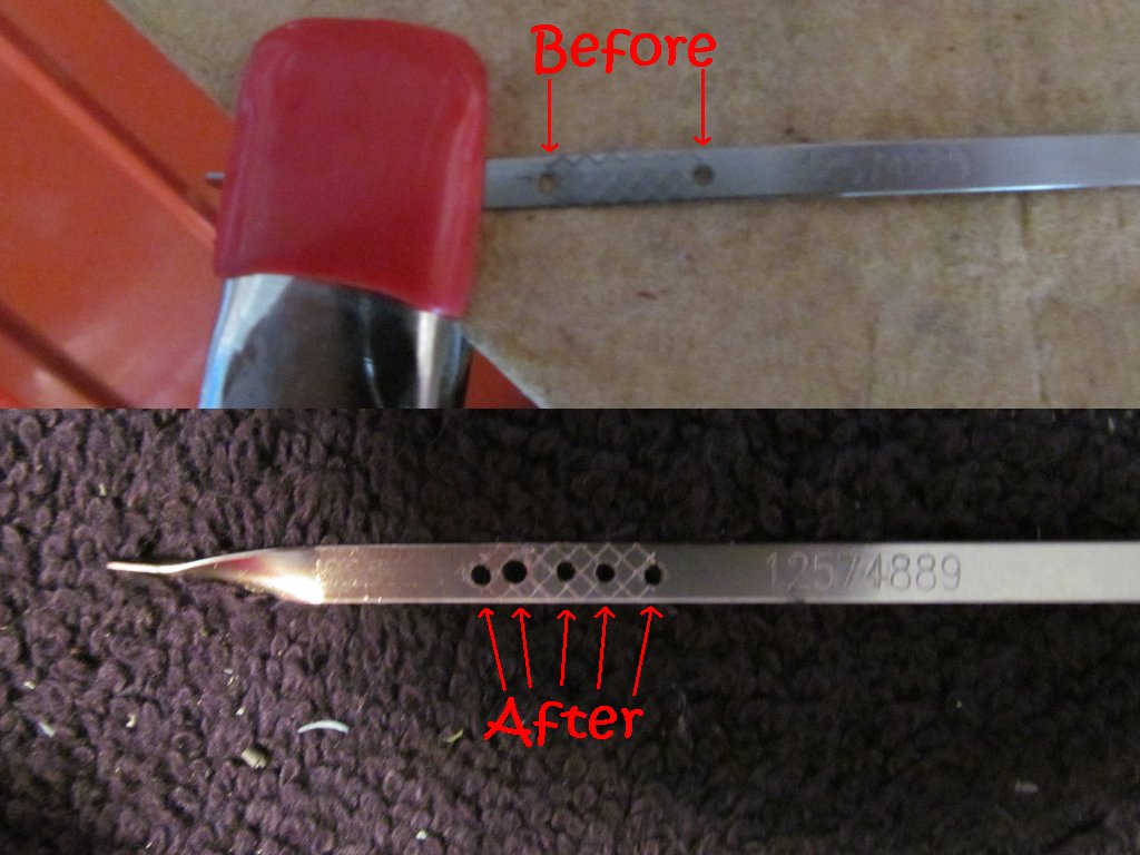
This modification will allow you to more accurately measure the oil level in your C5 Corvette.
It was always hard to accurately measure the oil level in the motor..... until now !
Now I can tell if I'm 3/4, 1/2, 1/4 full..... instead of just Full, or Low.
What I got to perform this job:
"1/16" Drill bit
Powered Drill
Try to center the holes as best as possible.
Clean all metal shavings from the dipstick before putting back in the car.
I tried it after a fresh oil change. I put in exactly 6.5 quarts of Mobil One.
The bottom 4 holes showed oil in them, the top hole showed no oil.
That told me I was close to full. Just added a pinch more and my top hole showed oil...
Something I had wanted to do for a while now... Just managed to remember when I was changing my oil today...
This modification will allow you to more accurately measure the oil level in your C5 Corvette.
It was always hard to accurately measure the oil level in the motor..... until now !
Now I can tell if I'm 3/4, 1/2, 1/4 full..... instead of just Full, or Low.
What I got to perform this job:
"1/16" Drill bit
Powered Drill
Try to center the holes as best as possible.
Clean all metal shavings from the dipstick before putting back in the car.
I tried it after a fresh oil change. I put in exactly 6.5 quarts of Mobil One.
The bottom 4 holes showed oil in them, the top hole showed no oil.
That told me I was close to full. Just added a pinch more and my top hole showed oil...
04-24-2012, 10:26 PM
#128
Instructor


Member Since: Apr 2010
Posts: 115
Likes: 0
Received 0 Likes
on
0 Posts
now quick question, are you taking measurements or did you just center drill it then center drill to the center hole? nice quick easy mod there!
05-24-2012, 10:18 AM
#131
Advanced
Member Since: May 2006
Posts: 76
Likes: 0
Received 0 Likes
on
0 Posts
http://forums.corvetteforum.com/1575191276-post26.html
some links on sources of parts/types I used that should make your work a lot easier (I ended up finding most of these parts on amazon for a lot less or in combo sets for the same price, use the pics for reference):
long bent nose pliers 16":
http://www.garrettwade.com/both-pliers/p/05R02.10/
universal joint:
http://www.sears.com/shc/s/p_10153_1...4250000P?mv=rr
wobbler
http://www.harborfreight.com/3-piece...set-67065.html
long extension type socket:
http://www.lislecorp.com/divisions/p...n=1&category=6
The first thing is to remove the vacuum hose than runs across the firewall as you attempt to get more clearance, it easily disconnects and gets you enough room to do the job.
Then the correct tools to do the job are:
1-1/16 socket (long socket about 3" long with thin walls -- the sensor isn't torqued hard but you don't want a short socket that's thick)
From this piece, I added the 3/8 swivel adapter, then a 3/8 extension wobbler (the socket snap on is curved vs standard extensions that are square)
then attach to ratchet, this is good to go
use good flashlights as it's dark down there to see what you are doing with the clip removal
for the clip I see people use hangers, I took a old brake spring clip for a drum brake I had and held it with long (about 16" needlenose pliers that had a 45' angle on them) and was able to get under the clip and pull it off. It worked great.
The issue I had was I took out the old sensor that was pegged high, put in the new one, proud of my work and then my new sensor pegged low
the one I had was aluminum, I went ahead and ordered from local parts store the brass version, it was much more expensive than the one I bought online.... I want to say it was about 75 dollars
I went back in did the damn job twice, this time I had to use the hanger method with the end of the hanger being a sharp upward hook.... hardest part of the job getting that clip off. The machining of these sensors isn't done where you install a new one and it threads up nice to get easy access (they figure you are doing the whole intake job)
the job was put back together this time the clip is on the backside which I'll be hoping it never fails again. Saved me a lot of time if I had not had a piece of crap sensor. The first one was an "OEM" sensor off ebay for about 45 dollars, guess the aluminum oem was junk (my original was brass). It may be vendor selling fake stuff too who knows.
Last edited by ricks98vette; 05-24-2012 at 11:13 AM. Reason: add links for parts needed
05-24-2012, 10:35 AM
#132
Race Director

the one I had was aluminum, I went ahead and ordered from local parts store the brass version, it was much more expensive than the one I bought online.... I want to say it was about 75 dollars
Saved me a lot of time if I had not had a piece of crap sensor. I think the first one I bought off amazon, I'd suggest staying clear of cheap ones and getting the brass version.
Saved me a lot of time if I had not had a piece of crap sensor. I think the first one I bought off amazon, I'd suggest staying clear of cheap ones and getting the brass version.
09-07-2012, 11:50 AM
#134
Team Owner
Thread Starter
10-14-2012, 07:06 PM
#135
Advanced
Member Since: Dec 2005
Posts: 82
Likes: 0
Received 0 Likes
on
0 Posts

I figured it out for the driver side. Next I will attempt the passenger side, which I see has two electrical plugs fastened to another connection on top of the bracket.
I assume I have to disconnect the battery and then disconnect the plugs before I take out the headlight bracket. Is that correct?
I assume I have to disconnect the battery and then disconnect the plugs before I take out the headlight bracket. Is that correct?
01-21-2013, 06:57 PM
#136
Racer

I'm an idiot. How or what do I do to find post #62 or whatever post are listed. Great info and I need all the help I can get but I tried searching and typing in post #62 with no success. Thanks.
 03-12-2013, 05:04 PM
#139
Instructor
Member Since: Mar 2011
Posts: 219
Likes: 0
Received 0 Likes
on
0 Posts
About the clima control.. my got completely dark, couldnt even see the display in the night.. it got pretty scary with soldering but i have to say i did a pretty good job. Now the display is like new! took me about 20 mins, half of that was the soldering gun heating up. fast and easy!
03-25-2013, 03:51 PM
#140
Pro

I can't take credit for this, but i haven't seen much on this forum about this so here's a little write up on how I did mine...
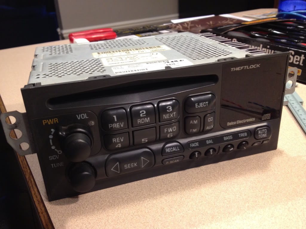
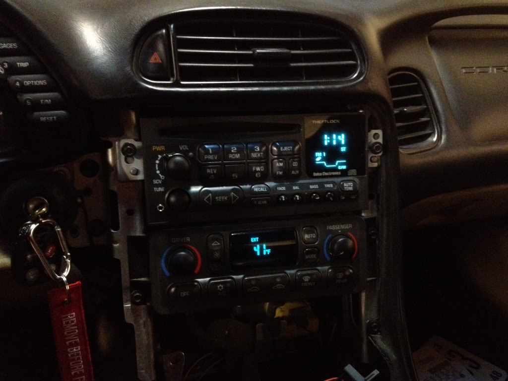
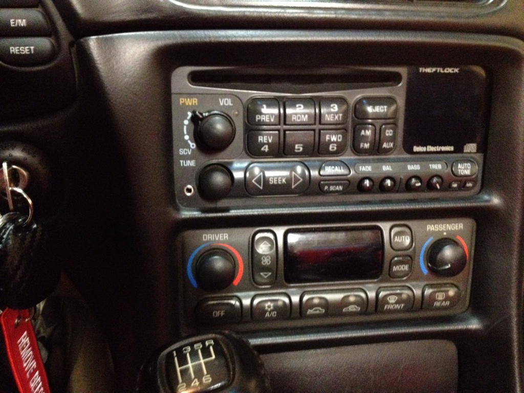
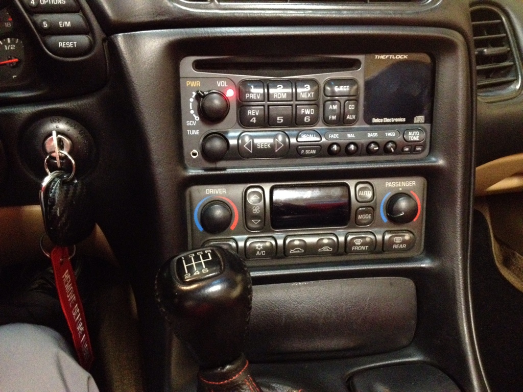
This is what we're starting with....
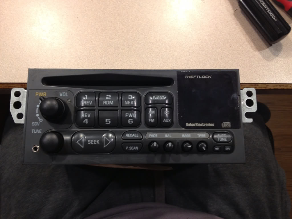
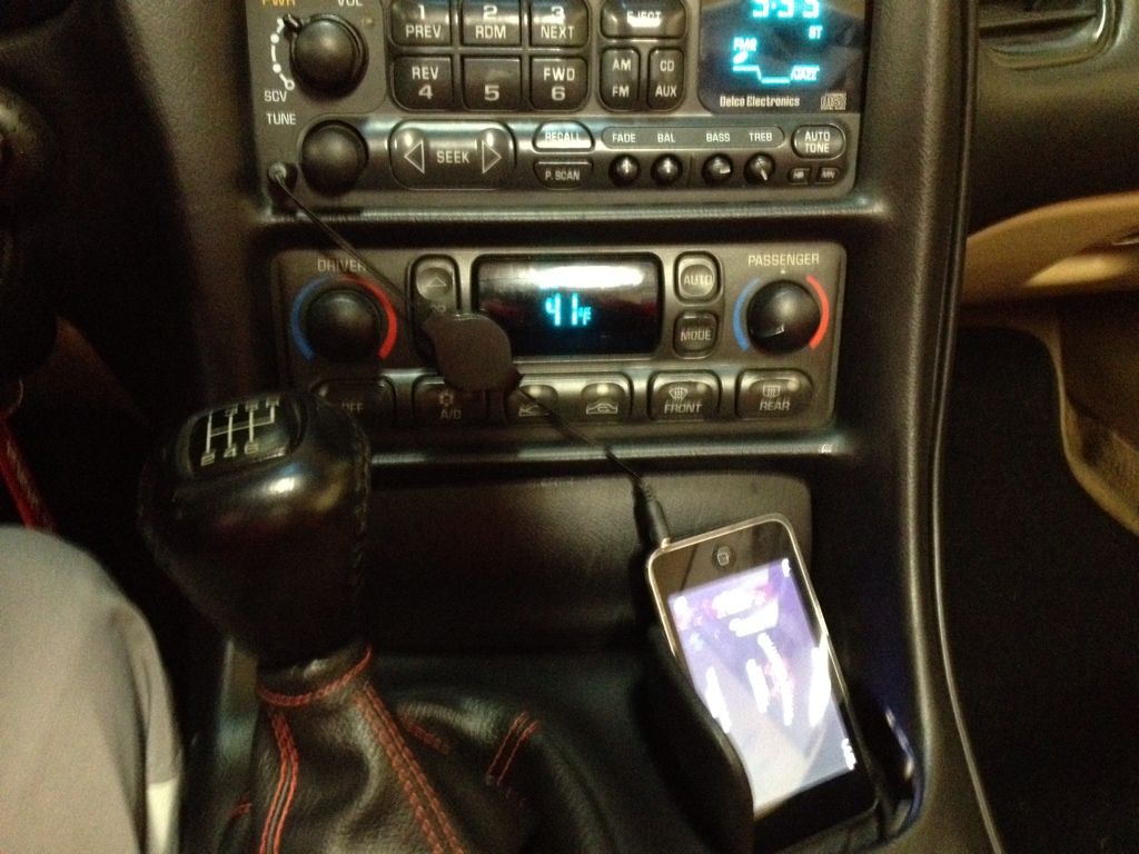
And here's what we're going for...
Again this only cost about $3 dollars and takes a mild bit of mechanical inclination so I wouldn't recommend attempting this if your not even comfortable removing your head unit yourself. If you are, then by all means your capable of getting the job done. This was the first time I've soldered anything since my young engineers class in the 8th grade but its fairly easy work. So even if you've never touched a soldering iron before you can still do this!
Step one.....
Go to RadioShack and pick up this little guy...
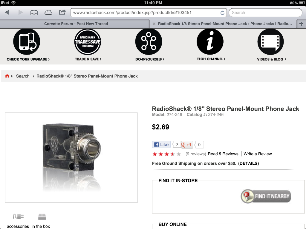
If you don't have a soldering iron, then go ahead and pick one up at RadioShack also, along with a spool of thin soldering wire. I bought the iron with a switch to change the iron from 15watt to 30 watt but found I used it on 30watt setting. You will also need a rotary tool if you dont already have one. I picked mine up at harbor freight for $8 with a coupon and it worked great!
Step two.....
Mark the outline of the radio bezel in the lower left corner of the faceplate of the head unit BEFORE removing anything from the car.... This is after I took it out but here is the mark you need to make with a pencil...
Step three...
If you have a convertible like mine you must remove the waterfall first....next, for all models, remove the center glove box and the center console/radio bezel. You can find a write up on how to do this in the tech forum, or over at vetteessentials.com. Next remove the head unit. PS MAKE SURE YOU KNOW YOUR UNLOCK CODE IF YOUR ANTITHEFT IS ACTIVE ON YOUR HEADUNIT as you will need to unlock it once you reinstall it when your finished. Take out the cd if there's one in it now.
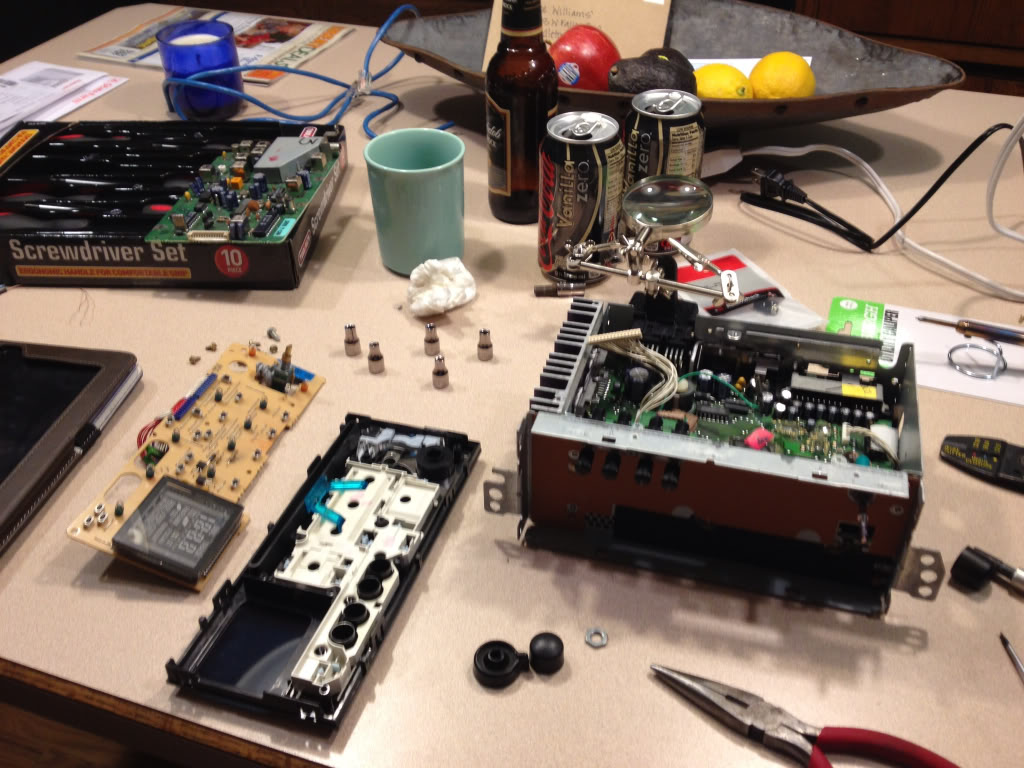
Go ahead and remove your headunit from the car and take it somewhere clean where you won't lose any parts, is well lit, and has an outlet. Since my fianc� doesn't mind me bringing my "projects" in the house, I chose my kitchen island.
Step four...
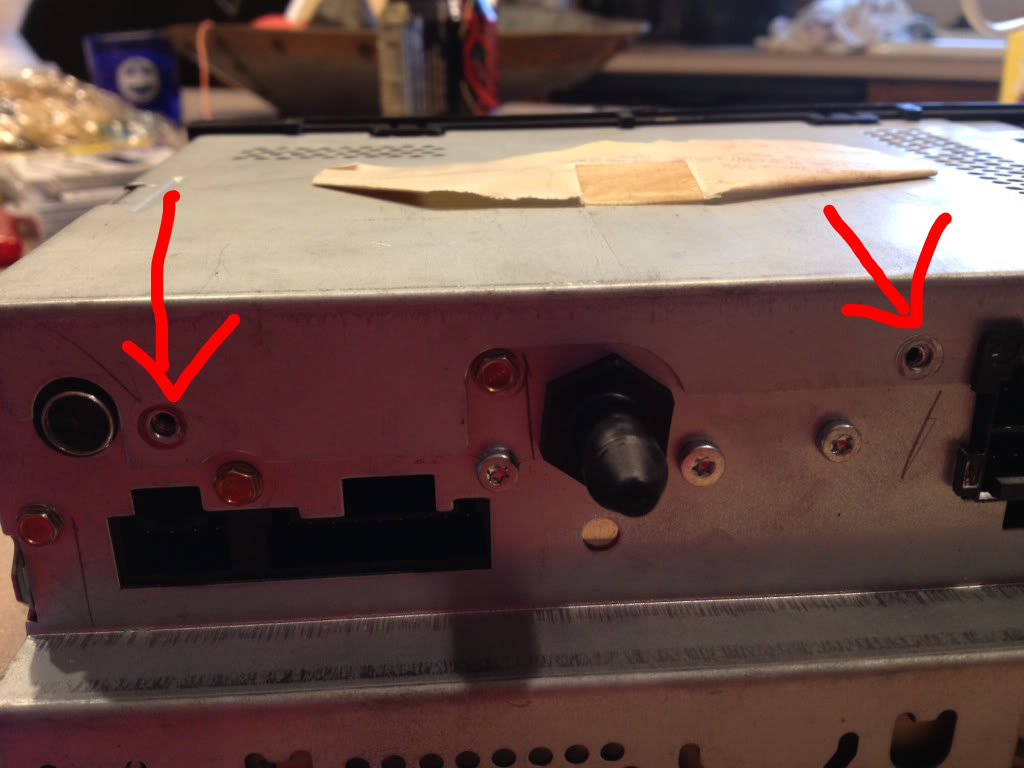
Go ahead and plug in your soldering iron and let it warm up while you start disassembling the head unit. Turn it upside down on your work area and remove these three screws...

Once the screws are out, pop off the metal lid.... You'll find this underneath...
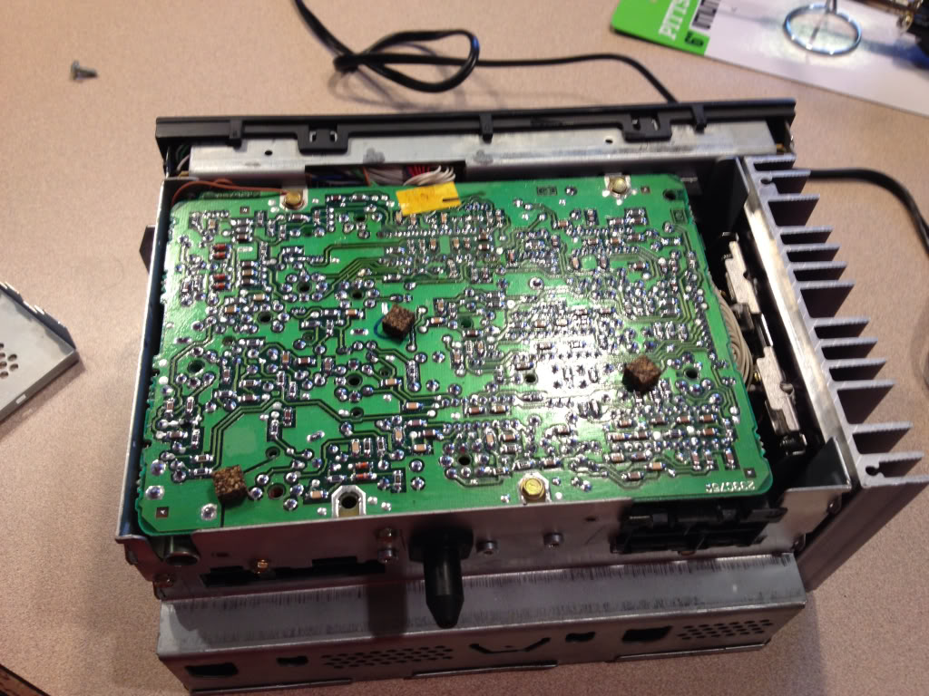
Go ahead and remove all of the remaining gold screws holding this circuit board down.... I think there were 3 on the board itself, then 3 or 4 more through the case on the sides. Underneath you'll find something similar to this. PS this picture is AFTER I had already unplugged a couple things and added a couple wires.... Ignore them for now.
THIS IS VERY IMPORTANT!!!! My car is a 98 and the Head unit is slightly different from some of the newer ones!!! You need to determine which style you have!!! The easiest way I think is to look at where this cable is on the circuit board.... My 98 is located here....
Newer cars it is located here...
It is very important to identify which style you have as it depends which wires we will cut later! I will refer to them as older style and newer style.
Unhook the green cable and the white row of cables connector circled above from the top circuit board you just removed and set it aside somewhere safe for now.
Step five....
Now you need to remove the face plate and the wires attaching it. It's a little tricky to release all the plastic tabs holding it to the case... Just be patient. Also pull the two ***** off and set them aside. I think once you remove the volume **** you will need to unscrew a little nut to separate it from the face. Put it somewhere safe.
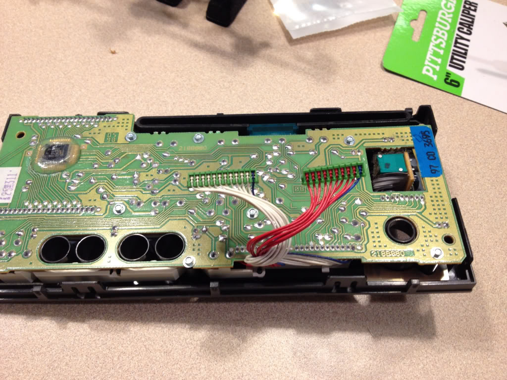
Next remove the tiny little screws holding on the circuit board to the face... I didn't have a socket small enough so I grabbed each with a set of needle nose pliers and very CAREULLY unscrewed them. You don't wanna scratch the circuit board!
Here's what you should have now....
Now remove the plastic piece and the metal pieces circled below.... This again is a little tricky just be mindful of the little plastic clips.
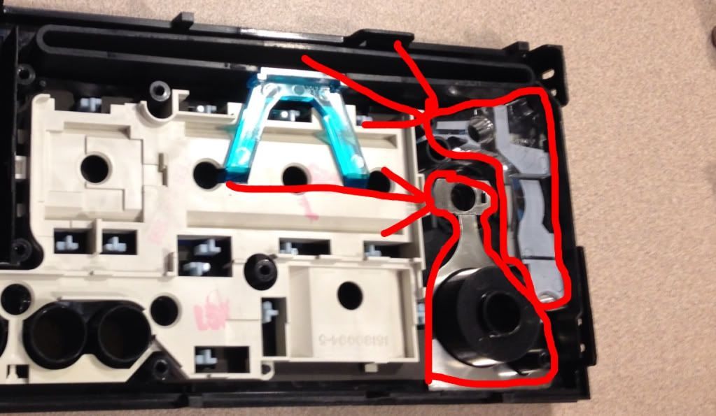
Once removed.... You have this....
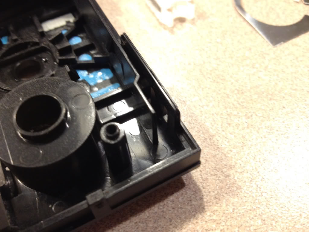
That little plastic tab over on the right will be in the way of the jack..... So get out your rotary tool and cut it out to end up with this...
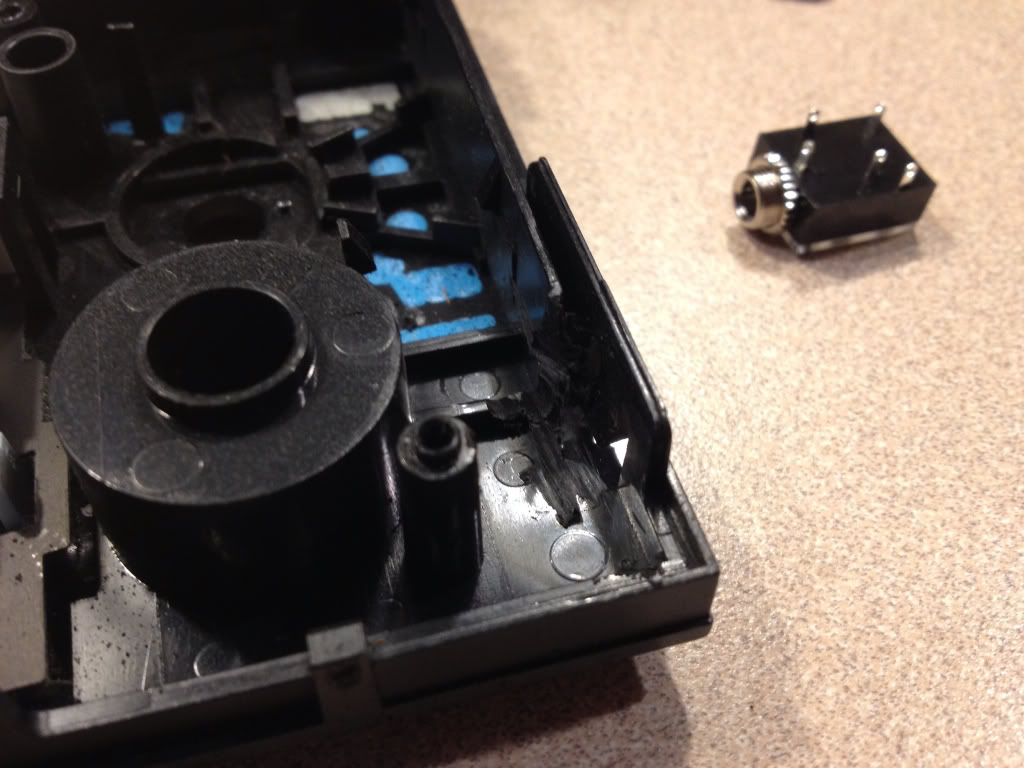
Now you will need to trim the corner off that little metal piece where you removed the plastic tab. Just cut off the corner. Reinstall the plastic and metal pieces.... Now test fit your jack...
If it fits then your good to move on...if not trim a little more with rotary tool. Next mark where you need to drill your hole.... Take some white out or anything else that will transfer and dab it on the metal part of the jack then retest fit... It should transfer to where you need to drill the hole... Not sure what size hole, but it should poke through perfectly flush from the front if you remove the little nut on the new jack.... You won't need it. Make sure before drilling your hole that you are inside your pencil marks from the bezel.
If all is well, move on...
Step six....
Now we get to solder! I used whats called cat5 cable. It's what you use to hook up your modem to your computer or router. Strip the outer layer and you will find small braided wires that are perfect for this job. I had an extra cable around the house, but they are cheap anywhere just cut off the plugs on the ends. I used the blue solid and blue striped as well as green solid and striped.... Then I separated the brown and used the solid brown as my ground.
My hands shake like a Parkinson's patient so I had a couple beers at this point and it steadied my hand a little ; )
Here is what you need to solder on your jack...
Here's a diagram
1 is grounded to case
2 goes to "plugged in" end of cut wire #4 (or #1)
3 goes to "unplugged" end of cut wire #4 (or #1)
4 goes to "unplugged end of cut wire #5 (or #3)
5 goes to " plugged in" end of cut wire #5 (or #3)
This is why it is VERY important to determine which style head unit you have, my 98 was the older style and you had to cut the 4th and 5th wires. The newer style, you have to cut the 1st and 3rd wires!!!!! I learned this the hard way and ruined the headphone port on my ipad. Luckily it was still under warranty and apple replaced it for free! But this is very very important! I've heard that the newer style can also use the 4th and 5th wires also, but not positive.... Will explain why later.
Step seven....
Now install your newly soldered jack into your drilled hole. I added a piece of electrical tape to the inside of the case by the jack so that the soldered connections wouldn't touch the metal case and short out. If its a little lose in the hole dont worry... When you reinstall the circuit board it will hold it tightly in place. I ground down the back of the circuit board slightly where it will make contact with the new jack, but I don't think it's necessary.
Next reinstall the circuit board to your face plate and reinstall your *****. Feed your wires carefully into the main case and snap the face plate back on.
Step eight....
Now your ready to cut the wires on the main connector. Look at it so the little black wire is to the right.....
If you have the older style like mine..... Cut the 4th and 5th wires leaving enough of each end to make soldered connections.
If you have the newer style cut the 1st and 3rd wires.
( PS ive heard you can also use 4th and 5th on newer models but haven't tested this)
Here's the connector again...
Now strip, twist together, and solder your connections as identified above. I also used heat shrink over the connections. If this is your first time soldering, I would practice with some extra wires making these connections! Also put a folded paper towel or something under your wires while soldering over the head unit. If you drip solder on the circuitry you could ruin the whole head unit!!!!!!
Note in my pictures I made the error of using the 1st and 3rd wires so you will see where I made the repairs. You won't have as many connections.
Here's after your connections are soldered and heat shrunk...
Again note I have extra connections due to my mistake mentioned earlier!
Tuck all your wires neatly into the case and reconnect the green cable and connection you unhooked earlier to the top circuit board set aside earlier. Run your ground out the corner. I attached a round ring terminal to the end of my ground and placed it under the bottom right screw in below picture...
While I had the head unit out, I cleaned the sensor with a qtip and alcohol. My CD player wouldn't play burnt CDs before now it does!! All it needed was a good cleaning!
Our friend toque has a write up on how to clean the eye on his website toquezo6.com! On my older style unit all I had to do was take the metal lid off the top of the case and I could see the eye. Newer ones are a little harder to get to.
Reattach all screws and lid and your good to put it back in the vette and give it a test!!! Make sure all wires are connected to the back of your HEADUNIT including the antenna!
Now is when you will have to unlock the HEADUNIT. Your manual tells you how.
Now if you did the 4th and 5th wires you will need to be on FM radio any station. Now plug in you iPod or other devise into its headphone jack and then into your new input. It will turn off the radio and play the iPod! You must unhook the connector from the face not just your device and it will go back to radio. Crystal clear quality of both now!!!
If you used 1st and 3rd wires you will need to be playing a cd in cd mode. Same thing here plug in the connector then your iPod and it will shut off cd and play your iPod! Unplug connected from faceplate and your back to cd!
This is why I think even the newer style can still use 4th and 5th wires it will just use radio instead of the CD player.
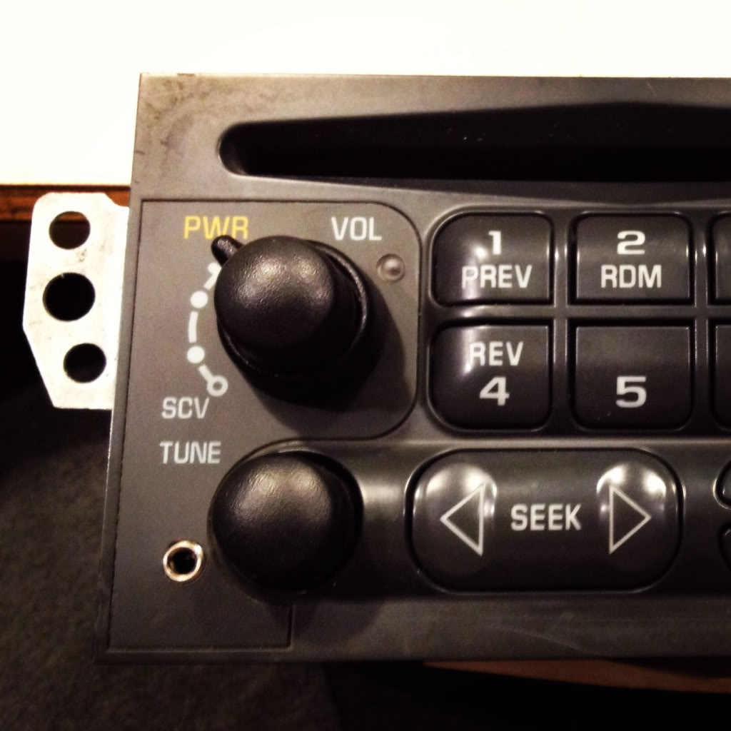
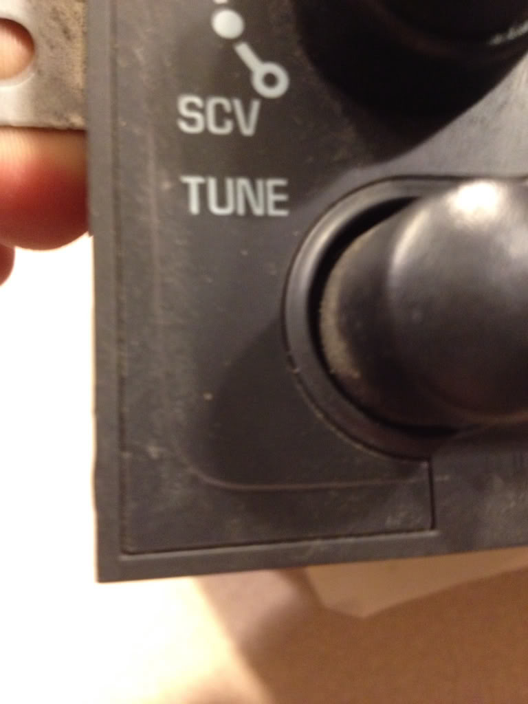
Here's the finished project....
Here's a video of how it works...
This is much easier than it seems and you will understand better when your looking directly at your head units "guts" than when looking at my pics.
Any questions don't hesitate to ask!
Tyler

This is what we're starting with....
And here's what we're going for...
Again this only cost about $3 dollars and takes a mild bit of mechanical inclination so I wouldn't recommend attempting this if your not even comfortable removing your head unit yourself. If you are, then by all means your capable of getting the job done. This was the first time I've soldered anything since my young engineers class in the 8th grade but its fairly easy work. So even if you've never touched a soldering iron before you can still do this!
Step one.....
Go to RadioShack and pick up this little guy...
If you don't have a soldering iron, then go ahead and pick one up at RadioShack also, along with a spool of thin soldering wire. I bought the iron with a switch to change the iron from 15watt to 30 watt but found I used it on 30watt setting. You will also need a rotary tool if you dont already have one. I picked mine up at harbor freight for $8 with a coupon and it worked great!
Step two.....
Mark the outline of the radio bezel in the lower left corner of the faceplate of the head unit BEFORE removing anything from the car.... This is after I took it out but here is the mark you need to make with a pencil...
Step three...
If you have a convertible like mine you must remove the waterfall first....next, for all models, remove the center glove box and the center console/radio bezel. You can find a write up on how to do this in the tech forum, or over at vetteessentials.com. Next remove the head unit. PS MAKE SURE YOU KNOW YOUR UNLOCK CODE IF YOUR ANTITHEFT IS ACTIVE ON YOUR HEADUNIT as you will need to unlock it once you reinstall it when your finished. Take out the cd if there's one in it now.
Go ahead and remove your headunit from the car and take it somewhere clean where you won't lose any parts, is well lit, and has an outlet. Since my fianc� doesn't mind me bringing my "projects" in the house, I chose my kitchen island.
Step four...
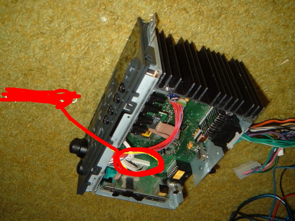
Go ahead and plug in your soldering iron and let it warm up while you start disassembling the head unit. Turn it upside down on your work area and remove these three screws...
Once the screws are out, pop off the metal lid.... You'll find this underneath...
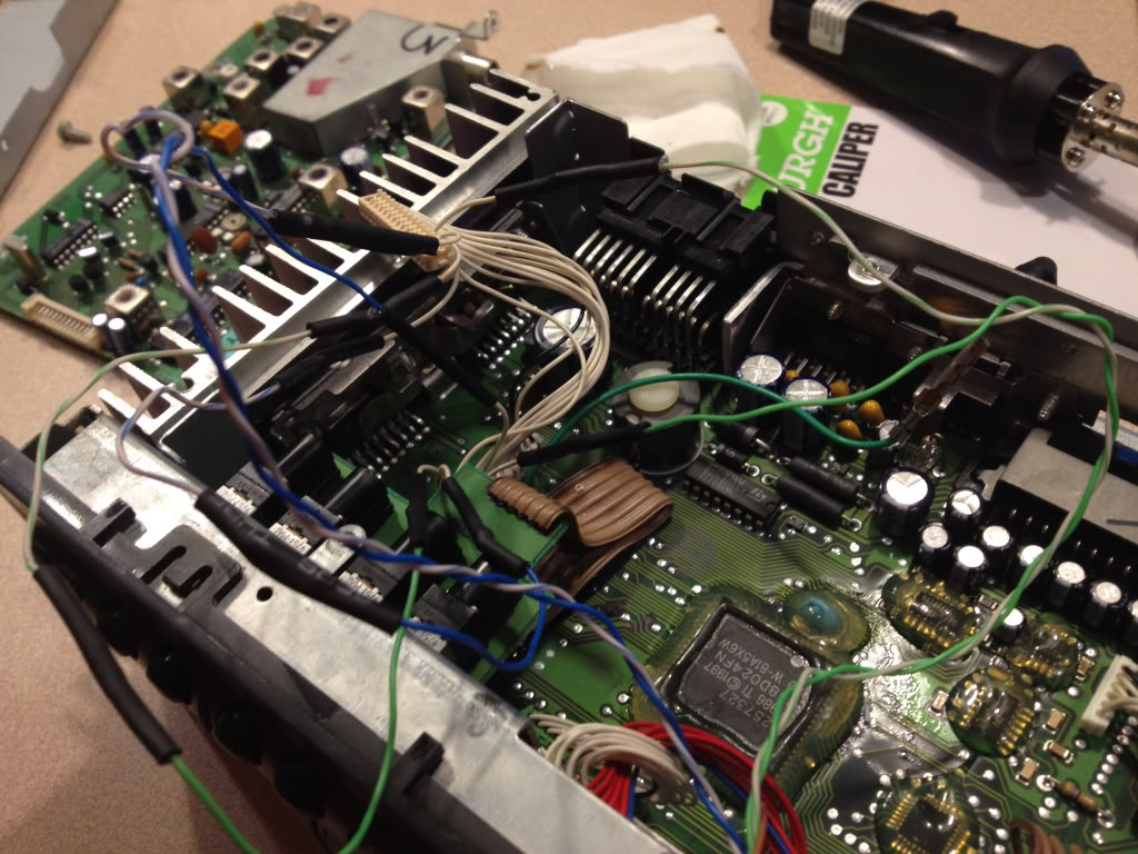
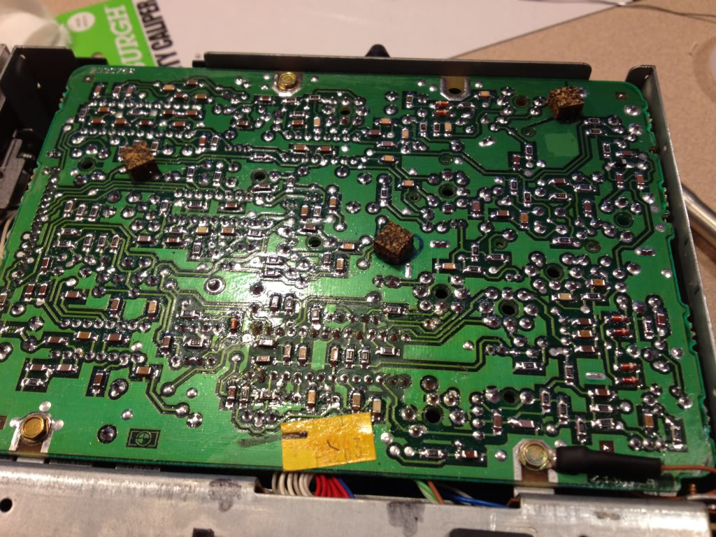
Go ahead and remove all of the remaining gold screws holding this circuit board down.... I think there were 3 on the board itself, then 3 or 4 more through the case on the sides. Underneath you'll find something similar to this. PS this picture is AFTER I had already unplugged a couple things and added a couple wires.... Ignore them for now.
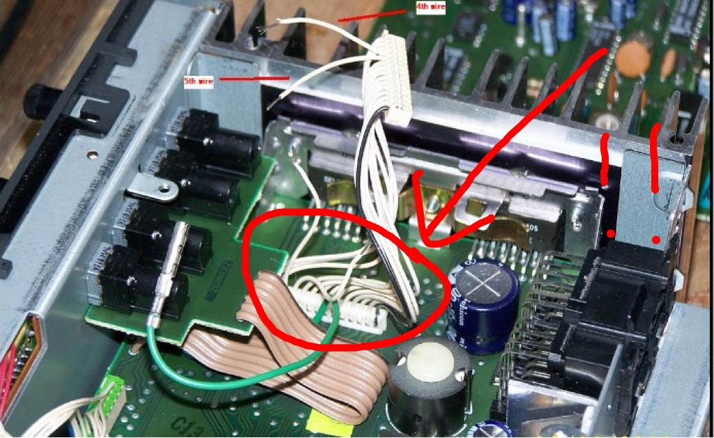
THIS IS VERY IMPORTANT!!!! My car is a 98 and the Head unit is slightly different from some of the newer ones!!! You need to determine which style you have!!! The easiest way I think is to look at where this cable is on the circuit board.... My 98 is located here....
Newer cars it is located here...
It is very important to identify which style you have as it depends which wires we will cut later! I will refer to them as older style and newer style.
Unhook the green cable and the white row of cables connector circled above from the top circuit board you just removed and set it aside somewhere safe for now.
Step five....
Now you need to remove the face plate and the wires attaching it. It's a little tricky to release all the plastic tabs holding it to the case... Just be patient. Also pull the two ***** off and set them aside. I think once you remove the volume **** you will need to unscrew a little nut to separate it from the face. Put it somewhere safe.
Next remove the tiny little screws holding on the circuit board to the face... I didn't have a socket small enough so I grabbed each with a set of needle nose pliers and very CAREULLY unscrewed them. You don't wanna scratch the circuit board!
Here's what you should have now....
Now remove the plastic piece and the metal pieces circled below.... This again is a little tricky just be mindful of the little plastic clips.
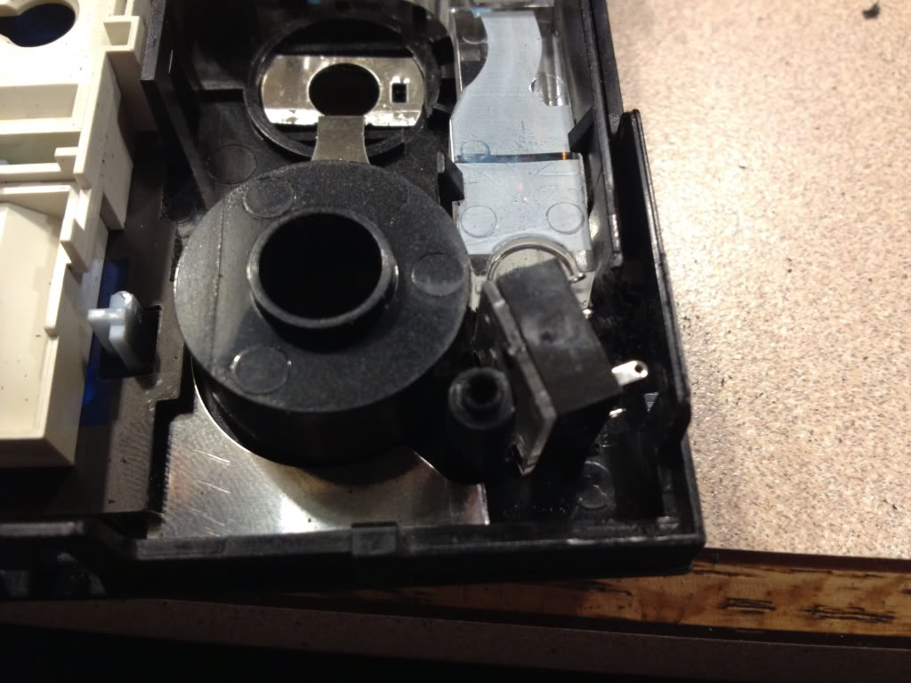
Once removed.... You have this....
That little plastic tab over on the right will be in the way of the jack..... So get out your rotary tool and cut it out to end up with this...
Now you will need to trim the corner off that little metal piece where you removed the plastic tab. Just cut off the corner. Reinstall the plastic and metal pieces.... Now test fit your jack...
If it fits then your good to move on...if not trim a little more with rotary tool. Next mark where you need to drill your hole.... Take some white out or anything else that will transfer and dab it on the metal part of the jack then retest fit... It should transfer to where you need to drill the hole... Not sure what size hole, but it should poke through perfectly flush from the front if you remove the little nut on the new jack.... You won't need it. Make sure before drilling your hole that you are inside your pencil marks from the bezel.
If all is well, move on...
Step six....
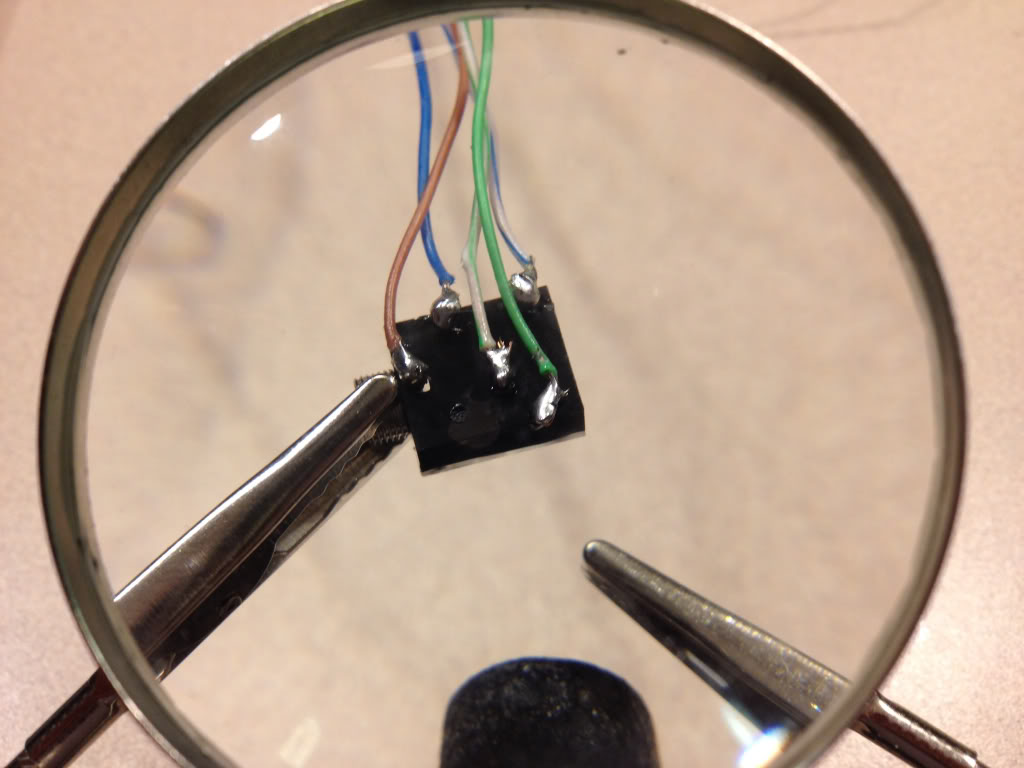
Now we get to solder! I used whats called cat5 cable. It's what you use to hook up your modem to your computer or router. Strip the outer layer and you will find small braided wires that are perfect for this job. I had an extra cable around the house, but they are cheap anywhere just cut off the plugs on the ends. I used the blue solid and blue striped as well as green solid and striped.... Then I separated the brown and used the solid brown as my ground.
My hands shake like a Parkinson's patient so I had a couple beers at this point and it steadied my hand a little ; )
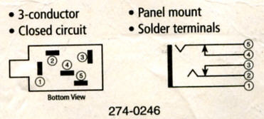
Here is what you need to solder on your jack...
Here's a diagram
1 is grounded to case
2 goes to "plugged in" end of cut wire #4 (or #1)
3 goes to "unplugged" end of cut wire #4 (or #1)
4 goes to "unplugged end of cut wire #5 (or #3)
5 goes to " plugged in" end of cut wire #5 (or #3)
This is why it is VERY important to determine which style head unit you have, my 98 was the older style and you had to cut the 4th and 5th wires. The newer style, you have to cut the 1st and 3rd wires!!!!! I learned this the hard way and ruined the headphone port on my ipad. Luckily it was still under warranty and apple replaced it for free! But this is very very important! I've heard that the newer style can also use the 4th and 5th wires also, but not positive.... Will explain why later.
Step seven....
Now install your newly soldered jack into your drilled hole. I added a piece of electrical tape to the inside of the case by the jack so that the soldered connections wouldn't touch the metal case and short out. If its a little lose in the hole dont worry... When you reinstall the circuit board it will hold it tightly in place. I ground down the back of the circuit board slightly where it will make contact with the new jack, but I don't think it's necessary.
Next reinstall the circuit board to your face plate and reinstall your *****. Feed your wires carefully into the main case and snap the face plate back on.
Step eight....
Now your ready to cut the wires on the main connector. Look at it so the little black wire is to the right.....
If you have the older style like mine..... Cut the 4th and 5th wires leaving enough of each end to make soldered connections.
If you have the newer style cut the 1st and 3rd wires.
( PS ive heard you can also use 4th and 5th on newer models but haven't tested this)
Here's the connector again...
Now strip, twist together, and solder your connections as identified above. I also used heat shrink over the connections. If this is your first time soldering, I would practice with some extra wires making these connections! Also put a folded paper towel or something under your wires while soldering over the head unit. If you drip solder on the circuitry you could ruin the whole head unit!!!!!!
Note in my pictures I made the error of using the 1st and 3rd wires so you will see where I made the repairs. You won't have as many connections.
Here's after your connections are soldered and heat shrunk...
Again note I have extra connections due to my mistake mentioned earlier!
Tuck all your wires neatly into the case and reconnect the green cable and connection you unhooked earlier to the top circuit board set aside earlier. Run your ground out the corner. I attached a round ring terminal to the end of my ground and placed it under the bottom right screw in below picture...
While I had the head unit out, I cleaned the sensor with a qtip and alcohol. My CD player wouldn't play burnt CDs before now it does!! All it needed was a good cleaning!
Our friend toque has a write up on how to clean the eye on his website toquezo6.com! On my older style unit all I had to do was take the metal lid off the top of the case and I could see the eye. Newer ones are a little harder to get to.
Reattach all screws and lid and your good to put it back in the vette and give it a test!!! Make sure all wires are connected to the back of your HEADUNIT including the antenna!
Now is when you will have to unlock the HEADUNIT. Your manual tells you how.
Now if you did the 4th and 5th wires you will need to be on FM radio any station. Now plug in you iPod or other devise into its headphone jack and then into your new input. It will turn off the radio and play the iPod! You must unhook the connector from the face not just your device and it will go back to radio. Crystal clear quality of both now!!!
If you used 1st and 3rd wires you will need to be playing a cd in cd mode. Same thing here plug in the connector then your iPod and it will shut off cd and play your iPod! Unplug connected from faceplate and your back to cd!
This is why I think even the newer style can still use 4th and 5th wires it will just use radio instead of the CD player.
Here's the finished project....
Here's a video of how it works...
This is much easier than it seems and you will understand better when your looking directly at your head units "guts" than when looking at my pics.
Any questions don't hesitate to ask!
Tyler
Last edited by Tyler_RN_EMT; 03-30-2013 at 12:03 AM.