
Johnny O'Connell Stage 1 Signature Series Suspension Kits - C5
 05-21-2017, 11:48 AM
#1
Premium Supporting Vendor
Thread Starter
Member Since: Oct 2004
Location: Manassas Park VA
Posts: 36,681
Received 421 Likes
on
322 Posts
St. Jude Donor '07-'08,-'13-'14, '16-'17

Johnny O'Connell
Stage 1
Signature Series Suspension Kits
Stage 1
Signature Series Suspension Kits
Looking for the most bang for the buck in your Corvette Suspension
Upgrade, then look no further than the the Johnny O'Connell Stage 1
Suspension Kit.
This kit comes with everything you need to Upgrade your Corvettes
Suspension to track level performance, while still keeping the drivablilty
of a street car. Upgrading these components will give your Corvette
a better balanced, better performing and more easily managed
suspension on the street as well as the track.
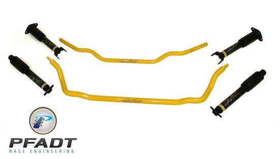
Each Kit Includes:
- (4) Tuned Johnny O'Connell Shocks
- (F/R) Johnny O'Connell Sway Bars
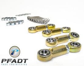
- Upgraded Sway Bar End Links
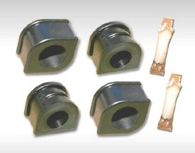
- (4) Sway Bar Bushings
Get your Stage 1 Package
with

at CCA
- (4) Tuned Johnny O'Connell Shocks
- (F/R) Johnny O'Connell Sway Bars
- Upgraded Sway Bar End Links
- (4) Sway Bar Bushings
Get your Stage 1 Package
with
at CCA

Regards
Chip
__________________
..................Click for


..................Click for
Last edited by CCA Corvette Parts; 03-02-2018 at 11:00 AM.
 06-08-2017, 10:26 PM
#2


Love them! Looked at many different setups before deciding on AFE. Great ride and now I'm looking for how they perform with new rubber and a square setup. BUT, I've run into a problem that I can't find an answer to:
I had the F45 suspension and when I replaced the shocks I added the Lingenfelter simulators to fool the computer. So far so good, then I removed the center console switch and tossed it out with the shocks. They are bye bye. I know that was really dumb! Now I screwed up the ESC control module and its throwing the warning "service active suspension". I examined the suspension damping engineering drawings and determined that I need to place a resistor shunt between pins 7 and 8 of the plug that goes to the computer. I've checked everywhere on this forum for some guidance and haven't found it yet, except to find someone with a Tech II tool who is willing to deactivate the RPO F45. Unfortunately I live in Maui and there are not a lot of sources. Does any one have the answer?
According to the drawings there are 4 resistors in the switch body. If I knew the ohm value between the two corresponding pins of the switch in any one of the switch positions I could make a shunt. Can someone out there who still has an F45 make a measurement for me and send it?
It would be sooooo much appreciated!
professor jim
06-09-2017, 11:24 AM
#3
Premium Supporting Vendor
Thread Starter
Member Since: Oct 2004
Location: Manassas Park VA
Posts: 36,681
Received 421 Likes
on
322 Posts
St. Jude Donor '07-'08,-'13-'14, '16-'17
Love them! Looked at many different setups before deciding on AFE. Great ride and now I'm looking for how they perform with new rubber and a square setup. BUT, I've run into a problem that I can't find an answer to:
I had the F45 suspension and when I replaced the shocks I added the Lingenfelter simulators to fool the computer. So far so good, then I removed the center console switch and tossed it out with the shocks. They are bye bye. I know that was really dumb! Now I screwed up the ESC control module and its throwing the warning "service active suspension". I examined the suspension damping engineering drawings and determined that I need to place a resistor shunt between pins 7 and 8 of the plug that goes to the computer. I've checked everywhere on this forum for some guidance and haven't found it yet, except to find someone with a Tech II tool who is willing to deactivate the RPO F45. Unfortunately I live in Maui and there are not a lot of sources. Does any one have the answer?
According to the drawings there are 4 resistors in the switch body. If I knew the ohm value between the two corresponding pins of the switch in any one of the switch positions I could make a shunt. Can someone out there who still has an F45 make a measurement for me and send it?
It would be sooooo much appreciated!
professor jim
I had the F45 suspension and when I replaced the shocks I added the Lingenfelter simulators to fool the computer. So far so good, then I removed the center console switch and tossed it out with the shocks. They are bye bye. I know that was really dumb! Now I screwed up the ESC control module and its throwing the warning "service active suspension". I examined the suspension damping engineering drawings and determined that I need to place a resistor shunt between pins 7 and 8 of the plug that goes to the computer. I've checked everywhere on this forum for some guidance and haven't found it yet, except to find someone with a Tech II tool who is willing to deactivate the RPO F45. Unfortunately I live in Maui and there are not a lot of sources. Does any one have the answer?
According to the drawings there are 4 resistors in the switch body. If I knew the ohm value between the two corresponding pins of the switch in any one of the switch positions I could make a shunt. Can someone out there who still has an F45 make a measurement for me and send it?
It would be sooooo much appreciated!
professor jim
Regards
Chip
06-09-2017, 07:41 PM
#4
Yep, that would be, but so far I have not ben able to find them.
If you or any reader of the forum know of anyone with a trashed vette that has the suspension switch, kindly let me know, OK?
If you or any reader of the forum know of anyone with a trashed vette that has the suspension switch, kindly let me know, OK?
07-13-2017, 06:04 PM
#6
Chris,
New housing without switch hole with replacement switch which is contained in a box which snaps in place with the **** removed did the trick, just like the simulators.
BTW: what does OTD mean?
professor jim
New housing without switch hole with replacement switch which is contained in a box which snaps in place with the **** removed did the trick, just like the simulators.
BTW: what does OTD mean?
professor jim