C6 C7 Corvette: How to Install Methanol Injection
Water/methanol injection systems have been around for almost 100 years, successfully used on fighter planes, race cars and yes, even Corvettes. Learn how to install one here.
This article applies to the C6 (2005-2013) and C7 Corvette (2014-current).
Many WWII aircraft, on both sides of the conflict, were equipped with a then-new technology known as “water injection” to create sudden bursts of power. These in turn helped increase the horsepower and torque required for maneuvers such as taking off, as well as successful dog-fighting. Typically the water was mixed 50/50 with alcohol, which both acted as an antifreeze to keep the water in a liquid state at high altitudes, while also being combustible.
Fluid injection is nothing new for cars, either. A new 1962 Oldsmobile F85 was not only the first production aluminum V-8 available with turbocharging, it also came with a “Fluid-injection Jetfire” engine. Available from the local Olds dealer, the fluid injection water/alcohol mixture was called “Turbo-Rocket Fluid.” The alcohol being used is actually methyl alcohol, also known as wood alcohol, wood naphtha or methanol — the type of alcohol that can make you blind if consumed. For this reason, these systems are now usually referred to as having “water/methanol injection,” or sometimes just a “meth system.” Not surprisingly, water/methanol injection is no stranger to car racing, either. Up until 2006, Indy Car racing used methanol as a fuel. Many who watched these races can remember pit fires (because methanol flames are invisible), showing frantic participants looking like they were performing a horrific pantomime routine.
Inexpensive window washer fluid can also be used, as long it’s rated to -20 degrees F (-29 degrees C), and thus close to being a 50/50 mix. Because of this fact, as well as the tight room under the hood of a Corvette, many custom installations of water/methanol injection systems actually share the window washer tank to feed the injector(s). Although there are many different kits available from various distributors (such as AEM, Snow Performance, and DevilsOwn), the following installation description looks at an Alcohol Injection Systems (AIS) Level 1 kit using their meth tank made specifically for the C6 Corvette.
Materials Needed
- Tin snips
- Wire stripper, crimp
- Trim panel removal tools
- Drill motor, drill set
- Tap and die set
The sudden injection of a water/alcohol vapor into an internal combustion engine intake can accomplish three things:
- Suppress detonation of the fuel, thus in effect raising the octane of the fuel, while at the same time decreasing knock.
- Cool the intake air by absorbing heat, which also increases its oxygen level.
- Increase the pressure inside the fired cylinder when the water part vaporizes, and the alcohol burns.
The result: a sudden surge of power.

This kit was chosen because it did not take over the windshield washer reservoir; its tank is installed in the car’s rear, out-of-sight.

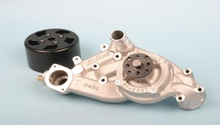
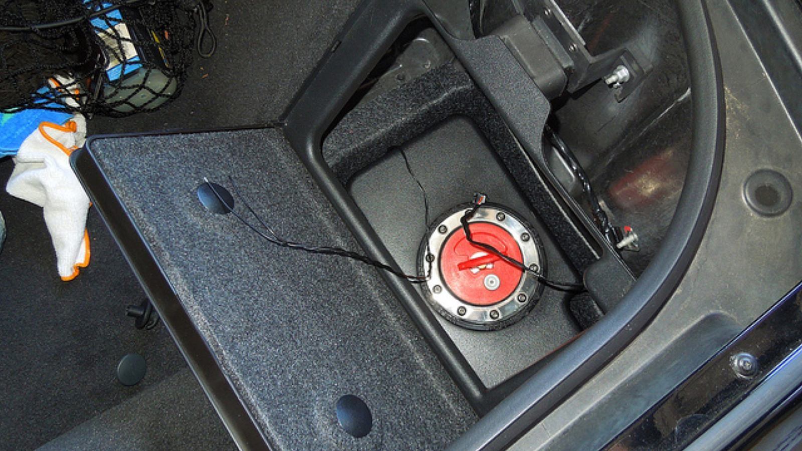
Step 1 – Place the water/methanol tank
Specifically, the 1.7 gallon tank fits nicely into the C6 storage compartment behind the driver seat. Built into the tank is a low fluid level sensor that shuts the pump down when the fluid runs out.
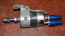
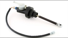
The pump comes with a weather-proofing cover to protect it from moisture. Holes for the mounting bracket and pump wires must be punched into the cover prior to its installation over the pump, and should be sealed with silicone when completed.

Step 2 – Mount the pump
The 250 PSI pump can go anywhere, as long as it's not near the exhaust or exposed to the hazards of the road. In Figure 5, it’s located directly below the tank, mounted onto the trunk storage container’s bottom.
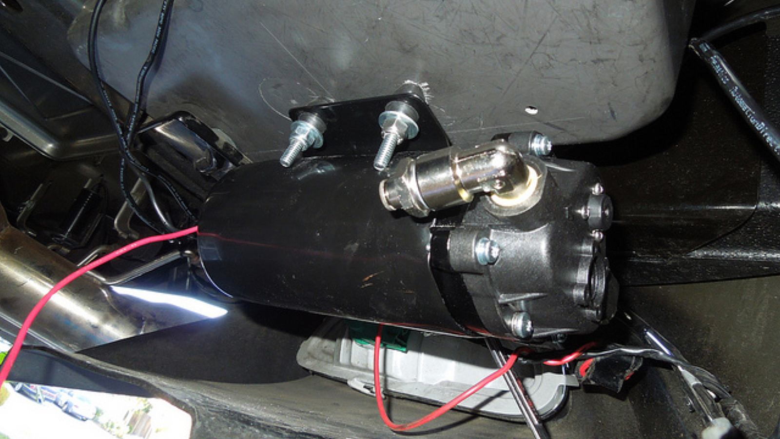
Fluid connections use push fittings for the supplied 1/4 inch Nylon tubing, which are very easy to install and remove — just press down on the fitting ring and pull out the tubing. Run the fluid tube from the tank into the pump input.
Step 3 – Connect the fluid lines
Once the pump was mounted to the bottom of the storage compartment, the tank was connected to the pump’s input connection, and the fluid line connected to the pump’s output connection.
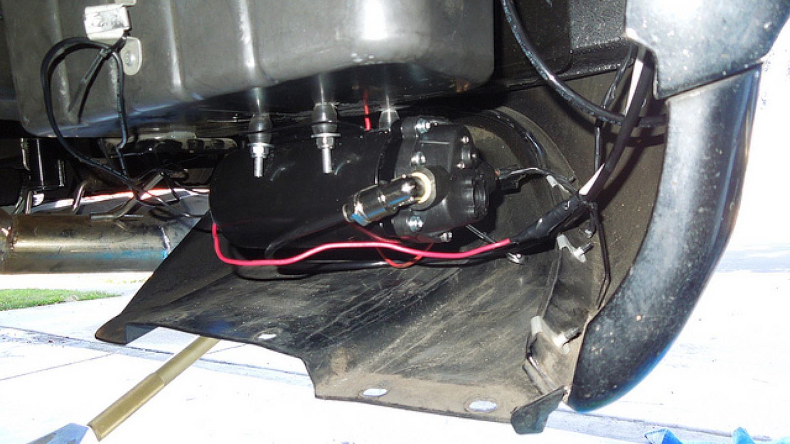
Step 4 – Connect the ground wire
Next came the wiring — a two-wire setup. At the pump the black 12v ground wire was attached to an existing ground connect off the frame rail.

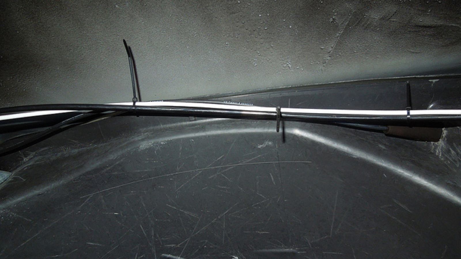
Step 5 – Run the tubing and hot wire to the engine compartment
The installer referred to in these photos decided to run the red 12v hot wire to the front of the car inside extra (white) vacuum tubing for protection. He zip-tied the white tubing (12v positive) and black tubing (meth) together, and snaked them up and over the wheel well inner liner, then through the rocker panel to the front of the bulkhead/firewall, and then up to the front of the engine compartment.
Step 6 – Connect the switch
In the engine compartment, the 12v hot wire from the pump is connected to the switch with a crimp-on slide connector to either of the two prongs. A hot wire runs from the other prong to an auxiliary electrical line or connection point. A relay (30 amp) needs to be used here, as the pump draws a fair amount of current, along with the fuse for the pump that comes with the kit.
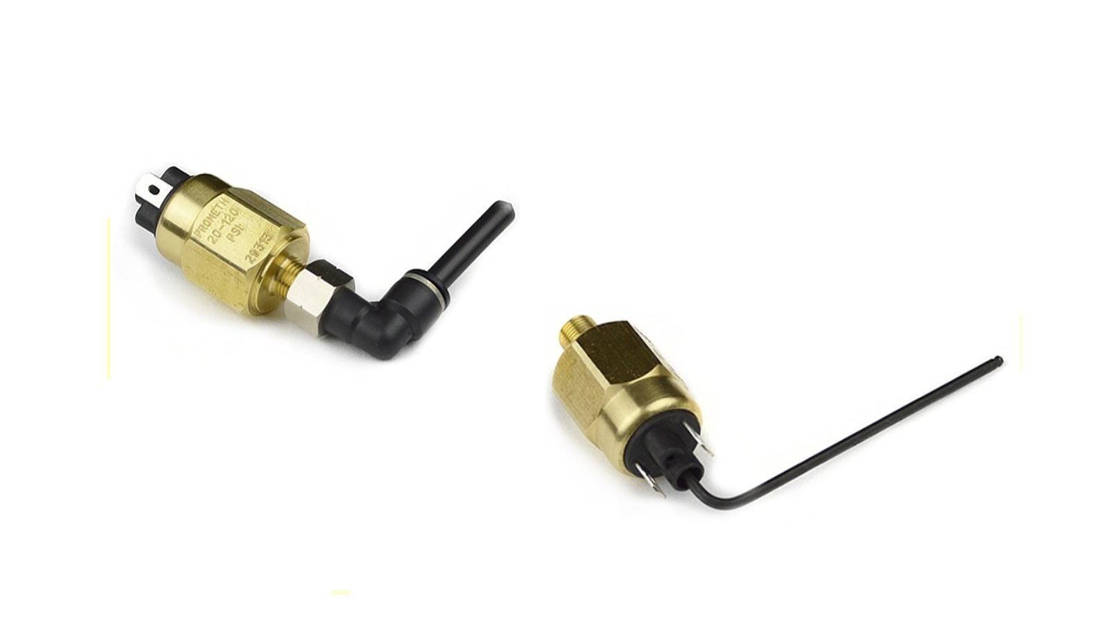
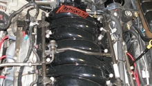
Step 7 – Connect the switch to a vacuum line
The boost activated switch is then attached to a “T” connecter spliced into a vacuum line coming directly off the intake manifold. The boost activated switch can be adjusted to anywhere between 1 to 25 PSI using the included hex (Allen) wrench.

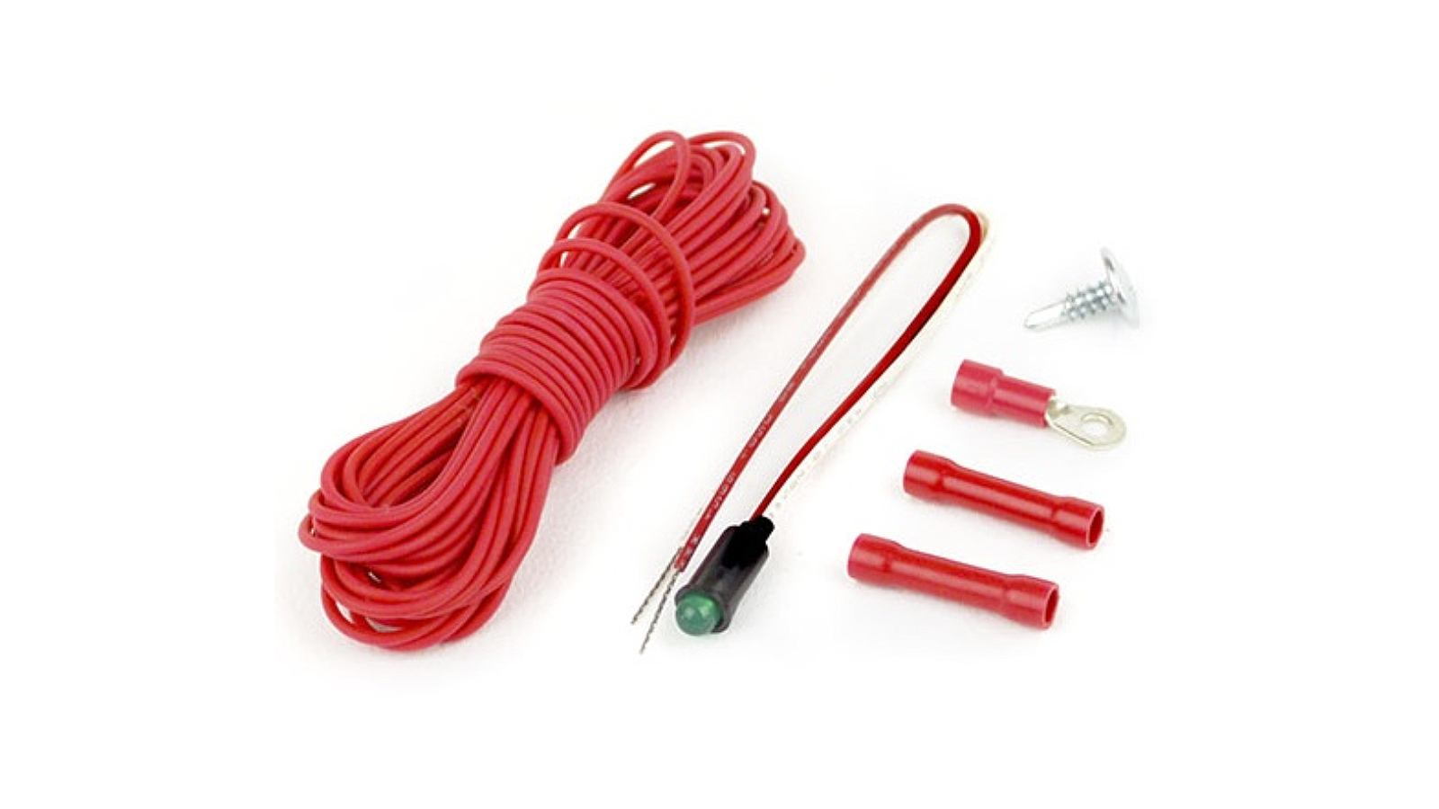
Step 8 – Connect an LED activation light
The kit also comes with an LED activation light which can be mounted inside the cab anywhere the driver can see it. It indicates the pump is working when it lights.
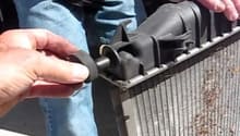
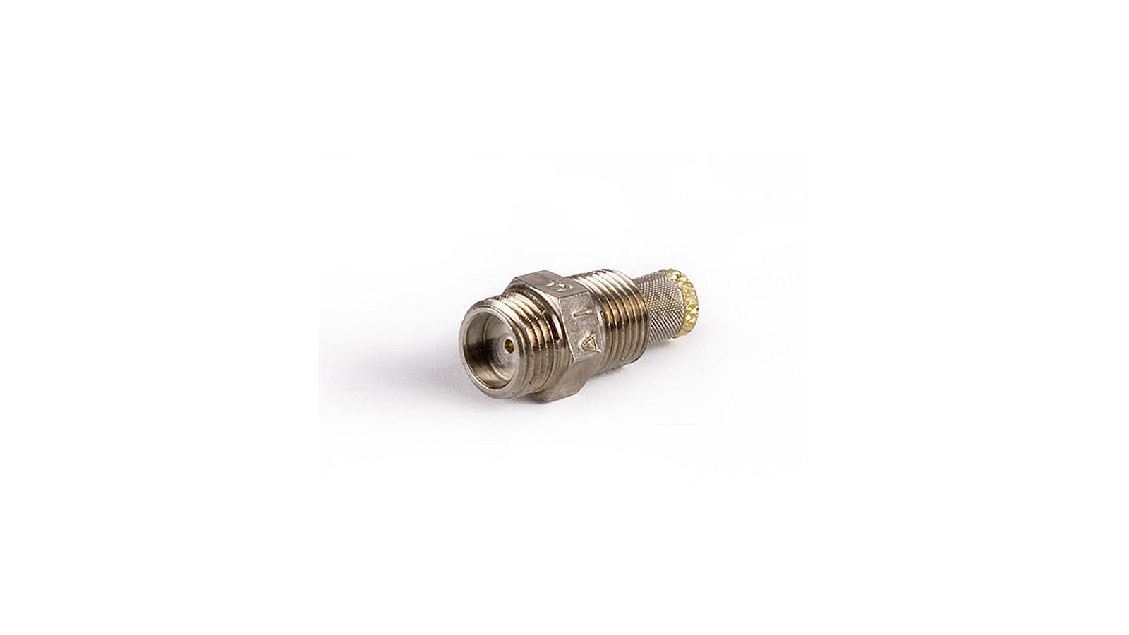
Step 9 – Connect the fluid line to the injector
The fluid line is connected to the injector, which can be mounted atop the throttle body before the throttle.
Step 10 – Mount the injector to the throttle intake
Mounting the injector to the throttle body will require drilling a “Q” size (0.3320 decimal) hole for the injector and using a special 1/8”-27 NPT for a tapered pipe thread connection.
However, some may prefer to instead mount it to a hard metal or rubber ring (such as a one-inch (25mm) wide stainless steel sheet metal band pop-riveted into a 4-inch or 100mm ring) mounted within the MAF bellows just before the worm screw clamp throttle connection, like the configuration shown in Figure 13. The injector can be held to the inside of the bellows using a 1/8-27 NPT panel nut, with a washer placed between the MAF bellows exterior and the injector.
Pro Tip
The injector should not be located close to, or before, the MAF sensor.

While driving, the system remains on stand-by until the set boost activation PSI level is attained. Then it will spray a controlled and continuous amount of water/methanol mixture through its nozzle(s) into the throttle. When the activation point is no longer met, the spray shuts off and the system goes on stand-by once again. The boost activated switch comes from the factory set to 10 PSI. Adjust the boost activated switch to the activation point you desire (between 1 to 25 PSI), and a tune-up at this point can also help smooth everything out.
Related Discussions
- Description of Mounting a Water/Methanol System - CorvetteForum.com
- Discussion About Injector Location - CorvetteForum.com
- Results with Naturally Aspirated Corvettes - CorvetteForum.com